Int. J. Electrochem. Sci., 7 (2012) 9488 - 9501
International Journal of
ELECTROCHEMICAL
SCIENCE
www.electrochemsci.org
Oxygen Evolution at Oxidised Iron Electrodes: A Tale of Two
Slopes
Michael E. G. Lyons* and Richard L. Doyle*
Trinity Electrochemical Energy Conversion & Electrocatalysis (TEECE) Group, School of Chemistry & CRANN, University of Dublin, Trinity College, Dublin 2, Ireland.
*
E-mail: melyons@tcd.ie ; rdoyle5@tcd.ie
Received: 9 August 2012 / Accepted: 1 September 2012 / Published: 1 October 2012
The electro-catalytic activity with respect to water oxidation to form molecular oxygen of iron oxyhydroxide thin films on iron support surfaces in aqueous base is described. A mechanism involving iron surfaquo groups is proposed in excellent agreement with the kinetic data. It is shown that the rate determining step of the oxygen evolution reaction depends strongly on the conditions under which the iron oxyhydroxide film is generated.
Keywords: Oxygen evolution electrocatalysis, iron oxyhydroxide modified electrodes, electrochemical water splitting.
1. INTRODUCTION
Alkaline water electrolysis has been proposed as an environmentally inoffensive route to the production of the large volumes of hydrogen gas required by a possible hydrogen economy [1-5]. In practice, the efficiency of water electrolysis is limited by the large anodic overpotential of the oxygen evolution reaction (OER) [5]. Over the past thirty years, considerable research effort has been devoted to the design, synthesis and characterization of OER anode materials, with the aim of achieving useful rates of active oxygen evolution at the lowest possible overpotential, in order to optimize the overall electrolysis process. Currently, the optimal OER anode materials are RuO2 and IrO2, since these oxides
transition metals should prove useful in elucidating whether a common reaction mechanism prevails. In the present paper, we focus on the oxygen evolution electrocatalytic behaviour of oxidised iron electrodes in alkaline solution. The kinetics of the oxygen evolution reaction at oxidised iron electrodes has been the subject of a number of recent publications emanating from our research group [10,11,13-16]. However, some outstanding issues regarding the factors affecting the Tafel slope still remain unsettled. In the current work we intend to collate and expand on our previous studies to provide a definitive Tafel analysis of the OER at oxidised iron electrodes. Using steady-state polarisation techniques, Tafel slopes and reaction orders with respect to hydroxide ion activity have been determined for both passive oxide and hydrous oxide covered iron electrodes. It will be shown that these kinetic parameters are quite sensitive to the conditions under which the electrodes are prepared. Finally, we propose a mechanism for the OER at oxidised iron electrodes which specifically takes into account the nature of the electrochemically generated hydrous iron oxide film, present on the surface of the Fe electrode during active oxygen evolution.
2. EXPERIMENTAL
All experiments were conducted in a conventional three electrode cell. The working electrode was constructed from 1.0 mm thick polycrystalline iron foil (as supplied by Alfa Aesar-Johnson Matthey, purity 99.9945% (metals basis)) with a geometric surface area of 0.16 cm2. Prior to each experiment the surface of the working electrode was polished successively with 1200 grit carbimet paper and a slurry of 0.3 μm alumina powder until a “mirror bright” finish was achieved. A platinum wire electrode (CH Instruments, cat no. CHI 115) was employed as the counter electrode and a mercury-mercuric oxide (Hg/HgO) reference electrode (CH Instruments, cat no. CHI 152) was utilized as the reference standard, therefore all voltages are quoted against this reference electrode. Aqueous NaOH solutions (in the range 0.1 to 5.0 M) served as both the electro-polymerization medium and the supporting electrolyte for the redox switching and electrocatalytic studies. These solutions were prepared from sodium hydroxide pellets (Sigma-Aldrich, minimum 99% purity) using Millipore water (resistivity > 15 MΩ cm). Before commencing each experiment, nitrogen gas was bubbled through the electrolyte solution for 20 min.
(50 mV) was recorded in a potential region where no Faradaic processes were occurring. The solution resistance was then calculated using the relationship, exp
u u DL
E t
i
R R C
, where ΔE is the magnitude of the potential step (V), Ru is the uncompensated solution resistance (ca. 0.4 Ω for 1.0 M NaOH), t is time (s) and CDL is the double layer capacitance (F).
The polymeric iron oxyhydroxide films were by multi-cycling a polycrystalline iron electrode in the requisite electrolyte solution. Two main methods were utilized:
Method A: the electrode was cycled between the switching potentials of -1.45 V and 0.35 V at a sweep rate of 0.35 V s−1 in 1.0 M NaOH.
Method B: the electrode was cycled between the switching potentials of -1.30 V and 0.75 V at a sweep rate of 0.40 V s−1 in 0.5 M NaOH.
Any deviations from these two methods are highlighted in the relevant sections as required. Films of different thicknesses were prepared by varying the number of growth cycles in the multi-cycling procedure. The charge storage capacity or redox capacity (Q) was determined, following the growth of each film, by integration of the peaks in a voltammetric profile recorded at a slow sweep rate (40 mV s−1). The redox capacity is directly proportional to the layer thickness.
3. RESULTS AND DISCUSSION
3.1. Passive oxide covered electrodes
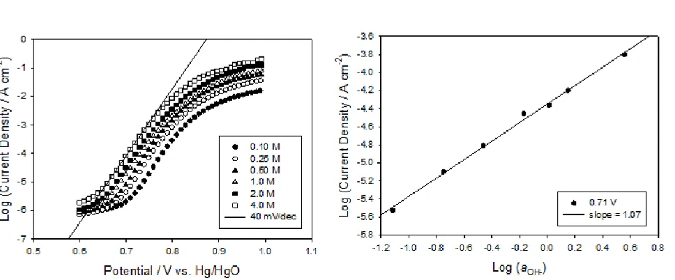
A logical place to start is with a new ‘bright’ un-cycled iron electrode. It is noteworthy at this stage that the OER does not occur on a metallic surface in the case of the un-cycled iron electrode. Upon introduction to alkaline solution and application of an anodic polarization regime, a passive oxide will form on the metal surface, and it is at the surface of this oxide that electrocatalysis of the OER occurs. Lyons and Brandon [10, 15-16] have discussed the kinetics of the OER at passive oxide covered iron electrodes. They showed that a Tafel slope ca. 40 mV dec−1 is obtained for an initially ‘bright’ electrode in 1.0 mol dm−3 NaOH but that this increases with subsequent polarisation experiments eventually stabilising in the range 45-48 mV dec−1. A reaction order mOH− ≈ 1 was
Figure 1. (a) Steady-state polarization curves recorded in solutions of varying NaOH concentration for a ‘bright’ un-cycled iron electrode. (b) The corresponding reaction order plot generated at a fixed potential of 0.71 V.
3.2. Hydrous oxide covered electrodes
[image:4.596.59.543.68.269.2]
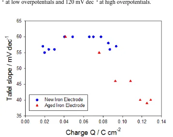
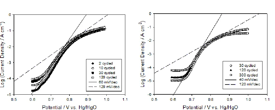
and 120 mV dec−1 Tafel behaviour. In contrast, the films prepared using method B gave Tafel slopes ca. 40 mV dec−1 at low overpotentials and 120 mV dec−1 at high overpotentials.
Figure 2. Tafel slopes measured in the lower overpotential region, for multi-cycled new and ‘aged’ iron elecrodes, plotted as a function of hydrous oxide charge capacity (Q).
[image:5.596.119.477.93.376.2]Figure 3. Steady-state polarization curves recorded for hydrous iron oxide films prepared using (a) method A and (b) method B as described above. The electrolyte solution was 1.0 M and 0.5 M NaOH respectively.
Table I. The Tafel slope b values obtained for a series of hydrous iron oxide films prepared using 30 growth cycles via method A and method B.
Number of 30 cycle growth experiments performed
Tafel slopes b / mV dec−1
After Type A Growth (Initial b = 40)a
After Type B Growth (Initial b = 60)b
1 53 57
2 57 53
3 56 53
4 60 52
5 61 50
6 60 48
a
The electrode had initially been conditioned using growth method B with a typical b = 40 mV dec−1.
b
Having successfully converted a 40 mV dec−1 slope into a 60 mV dec−1 slope using growth method A, an attempt was made to return the electrode to a 40 mV dec−1 slope using growth method B.
[image:6.596.57.537.375.528.2]
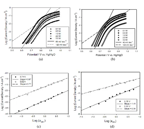
from literature values [18] for the mean ionic activity coefficients, γ±) are constructed in Fig. 4c and 4d for the 120 cycled Type A and B electrodes respectively. A reaction order mOH− ≈ 1 was determined for the Type A films with mOH− ≈ 1.5 for the Type B films at low overpotentials. Both films had an associated reaction order mOH− ≈ 1 at higher overpotentials. These results are not completely in accordance with previous accounts as Lyons and Brandon [13] have reported a reaction order mOH− ≈ 1.5 for their 30 cycled Type A film exhibiting a 60 mV dec−1 Tafel slope. Although we have been unable to reproduce this result it is interesting to note that a 60 mV dec−1 Tafel slope with an associated reaction order of mOH− ≈ 1.5 has also been reported for an ‘aged’ passive oxide covered iron electrode. If the multicycling procedure was performed on an ‘aged’ iron electrode the observed kinetic parameters could be due to the hydrous oxide film retaining the ‘aged’ character of the un-cycled electrode.
Potential / V vs. Hg/HgO
0.5 0.6 0.7 0.8 0.9 1.0 1.1
Lo
g (
Cu
rr
en
t De
nsi
ty
/ A c
m
-2 )
-5 -4 -3 -2 -1 0
0.1 M 0.5 M 1.0 M 2.0 M 4.0 M 40 mV dec-1
120 mV dec-1
(a) (b)
(c) (d)
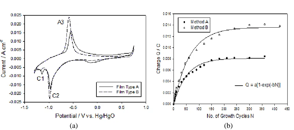
[image:7.596.59.540.271.702.2]capacity associated with the hydrous oxide peak A3 was significantly increased for the Type B film with Q values of ca. 49 mC cm−2 and 67 mC cm−2 for the Type A and B films respectively. This result is displayed in a more general sense in Fig 5b where the charge capacity Q is plotted as a function of the number of growth cycles N for method A and method B. Experimentally, it was found that the charge tends toward a constant limiting value as N is increased and can be fitted using the simple expression: , where where a = 8.1±0.2 or 13.6±0.3 mC and b = 191±1.3 or 156±1.1 cycles-1
for method A and B respectively. It is clear that significantly greater charge capacities can be achieved via method B, an observation which explains the discrepancy between the charges associated with the ‘new’ and ‘aged’ electrodes in Fig. 2 above. Additionally, a linear fit to the initial rising portion of the curve gave slopes of ca. 0.22 and 0.31 mC N−1 for method A and method B respectively indicating that the rate of film growth is higher for method B.
(a) (b)
Figure 5. (a) Cyclic voltammograms recorded for a Type A and Type B hydrous oxide film prepared via repetitive potential multicycling for N = 120 growth cycles. (b) The oxide charge capacity Q associated with the A3 peak as a function of the number of growth cycles N for method A and method B.
[image:8.596.62.539.341.553.2]
favours adsorption of this species. This apparently inhibits crystallization of the hydrous layer and the resulting more amorphous film is more effective in excluding water from the inner region of the oxide film- thereby inhibiting the growth of the charge storage layer.
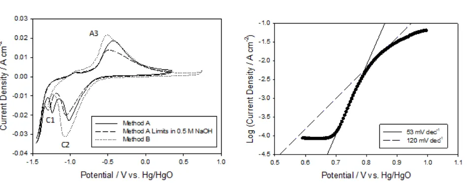
Indeed, apart from the variation in oxide charge capacity two further differences between Type A and Type B films are readily observable from the cyclic voltammograms presented in Fig. 5a. Firstly, the magnitude of the cathodic voltammetric peak located around −0.2 V is quite reduced for the Type B film. While the origin of this peak is uncertain it is thought to arise from ‘aging’ of the electrode as it is not present for a ‘fresh’ electrode. However, it is clear that the cause of this peak is somewhat inhibited for a Type B film especially considering the same electrode was used to prepare both films. Secondly, oxidation of the hydrous layer appears to be more facile for Type B films as evidenced by the marked decrease in the anodic A3 peak potential from −0.545 V to −0.585 V for the Type A and B films respectively. A possible explanation for this may be observed from the cyclic voltammograms presented in Fig. 6a which were recorded during the growth of typical Type A and Type B films. It is generally observed that hydrous oxide growth can be inhibited if the upper potential limit is too high, due to passivation of the metal surface [18]. However, this is clearly not the case here. Instead, the major difference between these two methods of growth is the extent to which the compact layer (C1 peak) is reduced during the growth of the film, as shown in Fig. 6a. In method A growth, the complete C1 reduction peak is present and the scan extends into the hydrogen evolution region whereas during method B growth only the rising portion of the C1 reduction peak is observed. To test this hypothesis a film was prepared using an intermediate method where the electrode was multicycled between the switching potentials −1.45 V and 0.35 V at 0.35 V s−1 (Method A parameters) in 0.5 M NaOH (Method B concentration). A corresponding cyclic voltammogram recorded during the growth of this film is also shown in Fig 6a. The significance of this method is that the degree of peak C1 reduction observed during the growth of the film was intermediate to methods A and B.
[image:9.596.62.539.482.670.2]In light of the above discussion, it seems likely that the kinetic properties of the hydrous film are quite sensitive to the extent of compact layer reduction during the growth of the film. Lyons and coworkers [11] have discussed in detail the factors affecting the growth of hydrous oxides. According to the latter authors, reduction of the compact oxide layer during hydrous oxide growth apparently facilitates rearrangement of oxy-cation species at the metal surface, leaving it in a somewhat disrupted state. On subsequent re-oxidation of the partially reduced metal surface the compact layer is restored but the outer region of the compact film is present in a more dispersed form. It may be that Type B films are less dispersed or more compact than Type A films due to the lower extent of compact oxide reduction during method B growth. If this is the case it could account for the variation in the voltammetric responses and the kinetic properties of the different types of hydrous oxide film.
3.3. Mechanism of oxygen evolution
In summary, any mechanistic interpretation of the OER at uncycled and multi-cycled Fe electrodes must account for the following kinetic parameters,
Uncycled passive oxide covered electrodes: A Tafel slope b = 2.303 × 2RT/3F (≈40 mV dec−1) and mOH− = 1 for fresh electrodes with the Tafel slope increasing to 2.303 × 4RT/5F (≈48 mV dec−1) following several polarization experiments.
Multi-cycled hydrous oxide covered electrodes: Dual Tafel behaviour for all multi-cycled iron electrodes with b = 2.303 × 2RT/F (≈120 mV dec−1) and mOH− = 1 at high overpotentials. At low overpotentials, the Tafel slope and reaction order depend on the method of growth with b = 2.303 × RT/F (≈60 mV dec−1) and mOH− = 1 for Type A hydrous oxides and b = 2.303 × 2RT/3F (≈40 mV dec−1) and mOH− = 1.5 for Type B hydrous oxides.
The kinetic data observed for uncylcled passive oxide coated electrodes has been discussed previously by Lyons and Brandon [15,16] in terms of a dual barrier mechanism originally proposed by Meyer [19] and MacDonald and Conway [20]. In a previous publication [21], we outlined a mechanism involving the active participation of the octahedrally co -ordinated Fe surfaquo groups which form the porous hydrous oxide layer. Here, we wish to ex tend this analysis and develop a more comprehensive mechanism which is in excellent agreement with the kinetic data. Our mechanistic thinking is guided by the earlier work of Kobussen and Broers [22]. This mechanism takes advantage of the fact that the hydrous layer contains considerable quantities of water molecules which facilitate hydroxide ion discharge at the metal catalytic site. Our new mechanism, represented schematically in Scheme A and also by the following reaction sequence:
(2)
(3)
(4)
(5)
(6)
(7)
In the latter reaction sequence S represents a surfaquo group attached to the hydrous oxide surface by bridging oxygen ligands, suggests the formation of an Fe(V) oxo intermediate. Indeed, a recent variable temperature mass spectrometry investigation has identified an Fe(V) oxo species as the catalytic centre in a biomimetric non-heme Fe complex [23].
The proposed catalytic cycle for the OER outlined in Scheme A, is analogous to those depicted for various different photocatalyst systems [24-26]. A common feature of these schemes is that the starting point for the OER catalytic cycle is usually represented as a metal coordinated water molecule.
of the catalytic cycle. Hence, the initial de-protonation step is depicted as a pre-step in Scheme A and the OER catalytic cycle begins with the resultant coordinated OH− ion which we label SOH. A second point of note regarding Scheme A is that the formation of the metal oxide SO (eqn. 3) and metal oxo SO (eqn. 4) species are designated as rate determining. Interestingly, in a recent theoretical study Muckermann et al. [26] showed, through the use of DFT calculations, that for a GaN/ZnO surface with high coverage of adsorbed OH− ions the intermediate associated with the highest energy was an oxide radical. Similarly, Rossmeisl et al. [27] performed a DFT study of the OER at RuO2
surfaces. They too found, for a surface saturated with adsorbed OH, that the highest energy intermediate was a surface oxygen species, in this case an oxo species. Considering these studies, the present mechanistic interpretation brings together a number of strands in the current understanding of the OER at metal oxides, and is clearly more satisfying than our previous presentation.A full kinetic analysis of the mechanism outlined above using the quasi-steady state approximation is presented a recent publication [21]. However, it is gratifying to note here that the current mechanism is in excellent agreement with the kinetic data. At low overpotentials the chemical formation of SO− (eqn. 3) is rate limiting with a predicted Tafel slope of ca. 60 mV dec-1 and a reaction order of unity. For high overpotentials it is reasonable to expect high surface coverage of SOH. Hence, the electrochemical formation of SO (eqn. 4) becomes rate limiting with a Tafel slope of ca. 120 mV dec−1 and a unit reaction order. The decrease in the low overpotential Tafel slope to 40 mV dec−1 for thick hydrous layers can be accounted for if the formation of SOOH (eqn.5) is assumed to be rate limiting. This step predicts a Tafel slope of ca. 40 mV dec−1 and a reaction order of unity. Finally if the decomposition of the peroxide SOOH species is rate determining, steady state analysis predicts a Tafel slope of 40 mV dec-1 and a reaction order with respect to hydroxide ion activity of 2. The observed diagnostic parameters of 40 mV dec-1 and reaction order of 1.5 with respect to hydroxide ion activity observed for type B hydrous oxides may well be attributed to the steps outlined in eqn.5 and eqn.6 being rate determining in different regions of the oxide film. The physical reason for the change in Tafel slope from 60 to 40 mV dec-1 is currently uncertain though a possible explanation might lie in increased stabilization of the previous intermediates in thicker layers. This would likely occur through intermolecular hydrogen bonding interactions with neighboring surfaquo groups.
The kinetic data for the passive oxide coated layers (48 mV dec-1, mOH- = 1) can also be
respectively. In this model the flux equation for the rate determining step, the effective Tafel slope and the effective reaction order are given by:
2 1 exp F F S OH F f Ka RT (8)
2.303 2.303 log 1 1 OH eff F S a F S RT RT b i F F (9) , FOH eff OH
S F
m m
(10)
In the latter expressions we note that the effective symmetry factor is:
FS S F S F
. Assuming that the SOOH intermediate decomposition is rate determining then we assign mOH 2. If the symmetry factors are assigned the reasonable values
1/ 2
S F
then F
1/ 2and mOH eff, 1and 2.303 4 0.047 / 5eff
RT
b V dec
F
. Hence our
kinetic data are rationalized.
4. CONCLUSIONS
Further details on the mechanism of the OER at oxide coated iron electrodes in aqueous alkaline solution are described. The catalytic chemistry at the oxidized iron surfaces is rich and the details of the electrochemical water splitting reaction at anodic potentials is shown to depend on the manner in which the electrode is electrochemically treated. The observed kinetics are adequately described in terms of a mechanism involving octahedrally coordinated surfaquo iron species embedded within the oxide layer.
ACKNOWLEDGEMENT
MEGL is grateful for the financial support of Enterprise Ireland Grant Number SC/2003/0049, IRCSET Grant Number SC/2002/0169 and the HEA-PRTLI Program. This publication has emanated in part from research conducted with the financial support of Science Foundation Ireland (SFI) under Grant Number SFI/10/IN.1/I2969.
References
7. K. Kinoshita, Electrochemical Oxygen Technology, Wiley-Interscience, New York (1992). 8. M. E. G. Lyons and M. P. Brandon, Int. J. Electrochem. Sci., 3 (2008) 1386.
9. M. E. G. Lyons and M. P. Brandon, Int. J. Electrochem. Sci., 3 (2008) 1425. 10.M. E. G. Lyons and M. P. Brandon, Int. J. Electrochem. Sci., 3, 1463 (2008) 1463.
11.M. E. G. Lyons, R. L. Doyle and M.P. Brandon, Phys. Chem. Chem. Phys., 13 (2011) 21530. 12.M. E. G. Lyons, L. Russell, M. O’Brien, R. L. Doyle, I. Godwin, M. P. Brandon, Int. J.
Electrochem. Sci., 7 (2012) 2710.
13.M. E. G. Lyons and M. P. Brandon, Phys. Chem. Chem. Phys., 11 (2009) 2203. 14.M. E. G. Lyons and R. L. Doyle, Int. J. Electrochem. Sci., 6 (2011) 5710. 15.M. E. G. Lyons and M. P. Brandon, J. Electroanal. Chem., 631 (2009) 62. 16.M. E. G. Lyons and M. P. Brandon, J. Electroanal. Chem., 641 (2010) 119. 17.M. E. G. Lyons and L. D. Burke, J. Electroanal. Chem., 170 (1984) 377.
18.R. A. Robinson and R. H. Stokes, Electrolyte Solutions, p. 492, Butterworth & Co. Ltd., London (1965).
19.R.E. Meyer, J. Electrochem. Soc., 107 (1960) 847.
20.J.J. MacDonald, B.E. Conway, Proc. Roy. Soc. London, Ser. A., 269 (1962) 419.
21.M. O’Brien, L. Russell, I. Godwin, R. L. Doyle and M. E. G. Lyons, ECS Trans., 45, 2012, in press. 22.A. G. C. Kobussen, G. H. J. Broers, J. Electroanal. Chem., 126 (1981) 221.
23.A. R. McDonald, L. Que, Nature, 3 (2011) 761.
24.M. Busch, E. Ahlberg and I. Panas, Phys. Chem. Chem. Phys., 13, 15069 (2011). 25.L-P. Wang, Qin Wu and T. Van Voorhis, Inorg. Chem., 49, 4543 (2010).
26.L. Duan, F. Bozoglian, S. Mandal, B. Stewart, T. Privalov, A. Llobet and L. Sun, Nature, 4, (2012) 418.
27.G. A. Lawrence, Introduction to Coordination Chemistry, p. 199, J. Wiley & Sons, West Sussex (2010).
28.X. Shen, Y. A. Small, J. Wang, P. B. Allen, M. V. Fernandez-Serra, M. S. Hybertsen and J. T. Muckerman, J. Phys. Chem, 114 (2010) 13695.
29.J. Rossmeisl, Z.-W. Qu, H. Zhu, G.-J. Kroes and J. K. Norskov, J. Electroanal. Chem., 607 (2007) 83.
