Int. J. Electrochem. Sci., 9 (2014) 380 - 389
International Journal of
ELECTROCHEMICAL
SCIENCE
www.electrochemsci.org
Electrolyte Research Near Graphite Particles by the Feedback
Current Using a Li Metal Probe
Fan Xu1, Cheolsoo Jung1,2*
1Graduate School of Energy Environmental System Engineering, University of Seoul, 163 Shiripdae-gil, Dongdaemun-gu, Seoul 130-743, Korea
2
Department of Chemical Engineering, University of Seoul, 163 Shiripdae-gil, Dongdaemun-gu, Seoul 130-743, Korea
*
E-mail: [email protected]
Received: 23 June 2013 / Accepted: 30 October 2013 / Published: 15 November 2013
The paper reports a home-made Li metal probe (LMP) to explore Li+ ion transport near graphite particles using the feedback current by the tip generation-substrate collection (TG-SC) mode of a scanning electrochemical microscope. Cyclic voltammetry revealed sufficient reproducibility and could measure the TG-SC feedback current over the charging graphite substrate. The graphite substrate at 0.0 V was imaged as hemi-spherical current domains ranging from ~mA to ~nA level according to the position being scanned by the LMP at 0.0 V. These results are attributed to a difference in the intercalating ability of Li+ ions into the charging graphite particles and are depending on the working substrate. Overall, electrolyte research using the feedback current near the anode particles is a promising method for improving the high rate performance of Li related batteries.
Keywords: Li metal probe; feedback current; tip generation; substrate collection; graphite electrode
1. INTRODUCTION
Until now, many studies have focused on developing active materials for LIBs with high performance balanced between power and capacity, and their practical use in EVs is expected to be realized in the near future [1,5-7]. Electrolyte research is also needed to obtain high power LIBs because the ion transport velocity through the electrolyte is much lower than the electron conduction velocity in the electrodes. Typically, electrolyte transport in LIBs has been analyzed mainly by electrochemical impedance spectroscopy (EIS), and their impedance components can be classified as the bulk resistance, film resistance, charge transfer resistance and diffusion resistance [8]. Because these components are strongly related to the mobility of Li+ ions, electrolyte design is the key technology for high power LIBs. Other analyses techniques, such as battery performance using a charge cycler and electrode surface deformation by field emission scanning electron microscopy (FESEM), transmission electron microscopy (TEM), atomic force microscopy (AFM) and scanning force microscopy (SFM) or X-ray diffraction (XRD), can be used to trace the electrochemical reaction generated on the electrodes of LIBs [8-10]. Unlike these types of scanning microscopes, scanning electrochemical microscopy (SECM) analyzes ion transport using the feedback current between the scanning probe and substrate [11,12]. Until now, the electrolyte distribution and ion transport near the LiCoO2 electrode have been examined using the feedback current between the charging electrode and
scanning Pt probe [13,14]. Based on these results, the transport behavior of Li+ ions near the LiCoO2
substrate can be analyzed as a part of a new technology in electrolyte research. The experimental mode used in previous studies was the substrate generation/tip collection (SG/TC) mode using a commercial Pt probe, which is effective in analyzing the transport of Li+ ions dissociating from the LiMxOy (M=Co,
Mn, Ni, etc.) substrate. Because ion transport in LIBs should be initiated by the intercalation process of Li+ ions into a graphite electrode, the SECM technique in tip generation/substrate collection (TG/SC) mode is essential for analyzing the transport of Li+ ions near the graphite electrode. This ion transport near the graphite electrode cannot be analyzed using the feedback current by the commercial Pt probe in SECM because of the limitation of the generating function. Therefore, in this study, the Li metal probe (LMP) was designed and used as a scanning probe for SECM experiments. A home-made LMP can generate Li oxidation, Li → Li+ + e-, directly above the graphite electrode. This paper also discusses electrolyte transport by TG/SC mode near the graphite electrode using a home-made LMP. As an electrochemical scanning probe, the LMP was compared with a commercial Pt probe by the probe scan curves (PSC) and SECM images. This study is expected to contribute to the development of electrolytes with lower transport resistance near the negative electrodes, such as graphite or silicon electrodes, which is essential for improving the power properties of LIBs for EVs and HEVs.
2. EXPERIMENTAL
2.1 Home-made Li metal probe (LMP)
1.1 ~ 1.2 mm and 1.5 ~ 1.6 mm, respectively, was purchased from Scientific Glass, Inc. and stretched under a lamp flame to make a conical capillary tip part.
OD: 230~240mm
ID: 20~24mm
(b) Silicone cap
Cu wire
SUS needle (18 mm)
Li metal
Capillary tube
~20mm
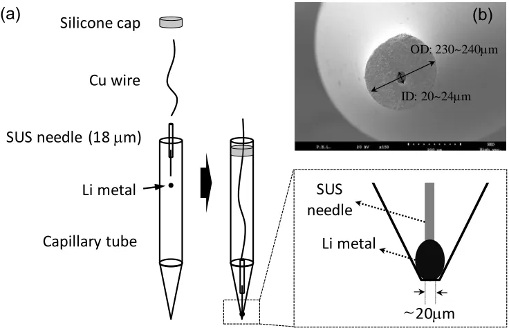
[image:3.596.110.478.134.371.2]Li metal SUS needle (a)
Figure 1. Inner components (copper wire as a conducting line and Li metal) of the LMP (a) and SEM image of its tip section (b)
This capillary was used as an outer insulating and supporting material of Li metal packed to its tip. A SUS needle with an 18 mm tip-diameter was welded to Cu wire for use as an electron connector. All subsequent steps to complete a glass-insulated LMP were carried out in the grove box; packing Li metal to the tip part of the capillary, inserting a SUS needle into the Li metal particle, sealing the end part of the glass tube and cutting its tip to make a conical and blunt tip, as shown in Fig.1(b). The tip state of the LMP was examined by optical microscopy (SEC-Zoom 4, Seoul Engineering Co., Ltd.) and Mini SEM (SNE-3000M, SEC Co., Ltd.), which contained an inner hole with a 20~24 mm diameter and an outer glass-insulator with a 230~240 mm thickness, as shown in Fig. 1(b). Li metal was inserted into the tip part of this inner hole to induce an electrochemical reaction at the interface adjacent to the electrolyte.
2.2 Electrochemical analysis using SECM
Ethylene carbonate (EC), diethyl carbonate (DEC), propylene carbonate (PC) and LiPF6 were
counter electrode, a graphite electrode with a 3.22 mm radius as working electrode 1 and an SECM probe as working electrode 2. The LMPs were home-made to have a 20~24 μm tip diameter, which was similar in size to a commercial Pt probe [15]. To obtain reliable data, the Pt probe was polished with diamond slurries (15 μm BASI) before each experiment and the LMP was used as a disposable probe. CV tests by the LMP were performed at a sweeping rate of 50 mV s−1 to determine the proper condition of the electrochemical reaction. The other experimental conditions using SECM were similar to those of our previous study to maintain theoretical continuity; 0.05 μm s−1 as a dipping rate toward the substrate for the PSC data and 60 μm s−1 as a probe scanning rate at a 20 μm position over the substrates for the SECM images [14, 15].
3. RESULTS AND DISCUSSION
3.1 Home-made LMPs and its CV curve
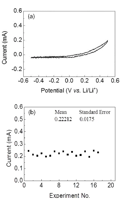
Figure 2. Cyclic voltammogram of the LMP in 1.0M LiPF6 EC/DEC (=3/7) (b) and its current
[image:4.596.161.407.317.725.2]
As depicted in Fig. 1(b), the home-made LMP had a conical and blunt tip, and its exterior was clean without remarkable protrusions that could impede the diffusion of the electrolyte components. A cross section of the glass capillary tip also showed that Li metal can come in contact with the electrolyte at the center of the glass insulator without any deviation of electrolyte diffusion near the LMP tip.
To confirm LMP as the Li metal working probe, CV experiments were carried out on 50 mV sec-1 over the potential range of -0.5 ~ +0.5 V (Li/Li+). Because Li metal was used as a reference electrode in this experiment, the current could be divided into the reduction part (negative potential) of Li+ ions solvated in the electrolyte and the oxidation part (positive potential) of the LMP based on 0.0 V. As shown in Fig. 2(a), the reduction current was almost undetectable. To be measured as a reduction current at the LMP, the transport velocity of the solvated Li+ ions should be as fast as the reduction velocity of Li+ ions at the interface of the LMP. If not, the reduction current cannot be measured due to an electrical double layer formed by PF6- ions remaining around the LMP. At the
positive potential region, however, the oxidation current increased exponentially with a sweeping potential. To be measured as an oxidation current, the electrolyte components, EC or DEC, need to exist around the LMP to participate in new solvation with the Li+ ions oxidizing from the LMP. The electrolyte used in this study, 1.0M LiPF6 and EC/DEC (=3/7), contains an abundance of EC and DEC,
which do not participate in the solvated structure when Li+ ions solvate with four ECs preferentially as reported elsewhere [15,16]. Therefore, Li+ ions oxidized from the LMP can form new solvation structures with extra EC or DEC, and the oxidation current increases exponentially according to the Butler-Volmer equation.
(1)
where n is the number of electrons transferred in the probe reaction (Li+ + e → Li or Li → Li+ + e in this study), F is Faraday’s constant, C is the concentration of Li+ ion, is the charge transfer coefficient, R is the gas constant, and is the sweeping potential. This is the main mechanism for the increasing oxidation current with a sweeping potential, which is different from that observed in the reduction potential range. These CV results showed that electrolyte transport between the LMP and graphite electrode can be measured by the feedback current (TG-SC mode) if the probe potential can be maintained at 0.0 V over the graphite electrode using SECM setups. On the other hand, the oxidation currents increased with increasing sweeping number, possibly due to deformation of the LMP surface by the rapid electrochemical reaction. Based on these experimental results, all the LMPs were used as disposal probes to avoid inconsistent results from the unevenness of the LMP surface in this SECM study. Finally, the reproducibility of the LMP was checked from the current at 0.5 V. As shown in Fig.2(b), the currents at 0.5 V were approximately 0.22 0.017 mA and its standard error was less than 1 % of the current.
3.2 PSC results by the home-made LMP over a graphite substrate
of the substrate, the current measured at the probe is only dependent on the concentration of the reacting materials according to the Butler-Volmer equation. On the other hand, the probe current is affected by the substrate when the probe approaches within the influence of the substrate. In this study, when the LMP approaches an insulating substrate for the redox reaction of Li, the LMP current, , decreases because the substrate blocks the diffusion of Li+ ions generated from the LMP to the bulk solution. In contrast, when the LMP approaches a conducting substrate for Li+ ions, the LMP can be oxidized or reduced more easily through the assistance of the conducting substrate.
70 60 50 40 30 20 10 0
0.16 0.18 0.20 0.22
0.24 Position A Position B
Curre
nt (mA)
Distance (mm)
Li+
Li+
Li+ Li+
Position A
Position B
approach
LMP (0V vs. Li/Li+)
LMP (0V vs. Li/Li+)
approach (a)
(b)
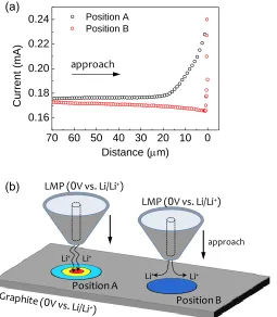
Figure 3. Probe scan curves (PSC) by the LMP at 0.0V over the graphite substrate being charged to 0.0V (a), and their feedback current schemes through the LMP (b). Positions A and B mean conducting and less conducting parts.
In Fig. 3, two types of typical PSC data, positive and negative feedback modes were selected between the LMP and graphite substrate that their potentials were maintained to 0.0 V. In positive feedback mode measured over position A of the graphite substrate, the current increased rapidly at 20
mm from the graphite substrate. This means that the oxidation current of the LMP is constant, at least
[image:6.596.178.433.229.521.2]Int. J. Electrochem. Sci., Vol. 9, 2014
386 These results mean that the graphite electrode is not uniform electrochemically and the LMP can discern to this difference in the charging graphite electrode on the micro-area level, such as the commercial Pt probe over a charging LiMO2 electrode.
3.3 SECM images of graphite substrates
Pt (0.3V vs. Li/Li+) LMP (0V vs. Li/Li+) LMP (0V vs. Li/Li+)
Li+
Li+
Li+ Li+
Li+
Li+
Li+
Graphite (0.0 V)
e
Li+
Solvated Li+
Li+intercalation Li+generation
Graphite (0.0 V) ×
e
Li+
Graphite (3.0 V) ×
0 20 40 60 80 100
0 20 40 60 80 100
x (mm)
y (
m
m)
0 20 40 60 80 100
0 20 40 60 80 100
x (mm)
y (
m
m)
0 20 40 60 80 100
0 20 40 60 80 100
x (mm)
y ( m m) -1.000E-4 2.900E-4 6.800E-4 0.001070 0.001200 -5.21 e-3 -3.82 e-3 -1.53 e-3 -9.21 e-3 -6.11 e-7 Current (A)
0 20 40 60 80 100
0 20 40 60 80 100
x (mm)
y (
m
m)
d =10mm
0 mm 100 mm 0 mm 100 mm 0 mm 100 mm
Current Substrate Current rich intercalation portion SECM image No SC Process
No TG Process TG/SC Loop
[image:7.596.82.524.180.477.2](a) (b) (c)
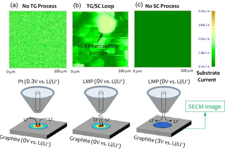
Figure 4. SECM images of graphite substrates measured by the feedback current using a commercial Pt probe and home-made LMP and their current schemes. Pt probe at 0.3V and graphite substrate at 0.0V (a), LMP at 0.0V and graphite substrate at 0.0V (b) and LMP at 0.0V and graphite substrate at 3.0V (c)
charging depth
3.0V
1.5V
1.0V
0.5V
0.0V
3.0
2.5
2.0
1.5
1.0
0.5
0.0
0.1
0.0
-0.1
-0.2
-0.3
-0.4
Cu
rren
t
(m
A)
[image:8.596.104.451.96.356.2]Potential (V
vs.
Li/Li
+)
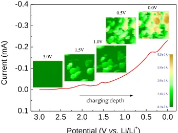
Figure 5. SECM images of a graphite electrode at various charged states from 3.0V to 0.0V (=Li/Li+). The current bar means the substrate current.
On the other hand, the graphite substrate at 0.0 V was imaged as various types of hemi-spherical current distributions, ranging from ~mA to ~nA level, according to the scanning LMP at 0.0 V, as shown in Fig. 4(b). The size of this hemi-spherical area corresponds approximately to the real size of graphite particles. Therefore, this current distribution in the SECM image means that the graphite particles can be imaged, respectively, by the feedback current with the scanning LMP. As shown in Fig. 4(c), no distinguishable images were obtained by the graphite substrate at 3.0 V, and its current was much weaker than the SECM results obtained by the graphite electrode at 0.0 V and Pt probe at 0.3 V. As the graphite electrode at 3.0 V does not require Li+ ions to maintain its potential, there is no reason to generate a feedback current even by the LMP at 0.0 V. These three SECM results suggest that the LMP can be an effective tool for analyzing the intercalating ability of Li+ ions near the charging graphite particles using the TG/SC feedback current. This is different from the SG/TC mode observed by the Pt probe near the LiCoO2 substrate at 4.0 V [15]. Although the Li ions needed to keep
can be measured as a quantitative current image using the TG/SC feedback current from the LMP. Thus far, many studies on the solid electrolyte interface (SEI) and the conductivity of the bulk electrolyte have been reported to improve the performance of LIBs, particularly for applications to hybrid electric vehicles (HEVs), which require high power performance. This paper suggests a new research method for improving the high rate performance of LIBs by examining the feedback current between the graphite particles and home-made LMP in SECM experiments. In particular, this type of research can work on designing the electrolyte for new anode substrates, such as metal alloy graphite or Li metal anodes.
4. CONCLUSION
In summary, we have demonstrated an LMP to examine Li+ ion transport over graphite particles using the feedback current of the TG-SC mode of SECM. The CV results by home-made LMPs showed sufficient reproducibility and possibility of measuring the TG-SC feedback current over the charging graphite substrate. The graphite substrate at 0.0 V was imaged as a hemi-spherical current distribution from ~mA to ~nA level according to the position of the scanning LMP at 0.0 V. This image was induced by the difference in the intercalating ability of Li+ ions into the charging graphite particles. Therefore, electrolyte research by studying the feedback current near the anode particles using the LMP can be a promising tool for improving the high rate performance of Li related batteries.
ACKNOWLEDGEMENT
This research was supported by the Converging Research Center Program through the Ministry of Science, ICT and Future Planning, Korea(2013K000291).
References
1. V. Etacheri, R. Marom, R. Elazari, G. Salitra and D. Aurbach, Energy Environ. Sci. 4 (2011) 3243 2. H. Chen, T. N. Cong, W. Yang, C. Tan, Y. Li and Y. Ding, Progress in Natural Science. 19 (2009)
291
3. H. Horie, T. Abe, T. Kinoshita and Y. Shimoida, WEV Journal 2 (2008) 25
4. C.E. Thomas, Int. J. Hydrogen. Energ. 34 (2009) 6005
5. I. R. M. Kottegoda, Y. Kadoma, H. Ikuta, Y. Uchimoto and M. Wakihara, J. Electrochem. Soc. 152 (2005) A1595
6. K. Amine, J. Liu, I. Belharouak, S.-H. Kang, I. Bloom, D. Vissers and G. Henriksen, J. Power Sources 146 (2005) 111
7. Y. Saito and Md. K. Rahman, J. Power Sources 174 (2007) 877
8. M. Kerlau, M. Marcinek, V. Srinivasan and R. M. Kostecki, Electrochimica Acta. 52 (2007) 5422 9. J. Saint, M. Morcrette, D. Larcher, L. Laffont, S. Beattie, P. Pérès, D. Talaga, M. Couzi and
J.-M. Tarascon, Adv. Funct. Mater. 17 (2007) 1765
10.S-K Jeong, M. Inaba, Y. Iriyama, T. Abe and Z. Ogumi, Electrochimica Acta. 47 (2002) 1975 11.A. L. Barker, J. V. Macpherson, C. J. Slevin and P. R. Unwin, J. Phys. Chem. B 102 (1998) 1586 12.P. Sun, F. O. Laforge and M. V. Mirkin, Phys. Chem. Chem. Phys. 9 (2007) 802
13.B. Beak, F. Xu and C. Jung, Solid State Ionics 202 (2011) 40
15.F. Xu, B. Beak and C. Jung, J Solid State Electrochem. 16 (2012) 305