ScienceDirect
Available online at Available online at www.sciencedirect.comwww.sciencedirect.com
ScienceDirect
Procedia Manufacturing 00 (2017) 000–000
www.elsevier.com/locate/procedia
* Paulo Afonso. Tel.: +351 253 510 761; fax: +351 253 604 741
E-mail address: [email protected]
2351-9789 © 2017 The Authors. Published by Elsevier B.V.
Peer-review under responsibility of the scientific committee of the Manufacturing Engineering Society International Conference 2017.
Manufacturing Engineering Society International Conference 2017, MESIC 2017, 28-30 June
2017, Vigo (Pontevedra), Spain
Costing models for capacity optimization in Industry 4.0: Trade-off
between used capacity and operational efficiency
A. Santana
a, P. Afonso
a,*, A. Zanin
b, R. Wernke
b a University of Minho, 4800-058 Guimarães, PortugalbUnochapecó, 89809-000 Chapecó, SC, Brazil
Abstract
Under the concept of "Industry 4.0", production processes will be pushed to be increasingly interconnected, information based on a real time basis and, necessarily, much more efficient. In this context, capacity optimization goes beyond the traditional aim of capacity maximization, contributing also for organization’s profitability and value. Indeed, lean management and continuous improvement approaches suggest capacity optimization instead of maximization. The study of capacity optimization and costing models is an important research topic that deserves contributions from both the practical and theoretical perspectives. This paper presents and discusses a mathematical model for capacity management based on different costing models (ABC and TDABC). A generic model has been developed and it was used to analyze idle capacity and to design strategies towards the maximization of organization’s value. The trade-off capacity maximization vs operational efficiency is highlighted and it is shown that capacity optimization might hide operational inefficiency.
© 2017 The Authors. Published by Elsevier B.V.
Peer-review under responsibility of the scientific committee of the Manufacturing Engineering Society International Conference 2017.
Keywords: Cost Models; ABC; TDABC; Capacity Management; Idle Capacity; Operational Efficiency
1. Introduction
The cost of idle capacity is a fundamental information for companies and their management of extreme importance in modern production systems. In general, it is defined as unused capacity or production potential and can be measured in several ways: tons of production, available hours of manufacturing, etc. The management of the idle capacity
Procedia Manufacturing 15 (2018) 992–999
2351-9789 © 2018 The Authors. Published by Elsevier B.V.
Peer-review under responsibility of the scientific committee of the 17th International Conference on Metal Forming. 10.1016/j.promfg.2018.07.395
10.1016/j.promfg.2018.07.395 2351-9789
© 2018 The Authors. Published by Elsevier B.V.
Peer-review under responsibility of the scientific committee of the 17th International Conference on Metal Forming.
Available online at www.sciencedirect.com
ScienceDirect
Procedia Manufacturing 00 (2018) 000–000
www.elsevier.com/locate/procedia
2351-9789 © 2018 The Authors. Published by Elsevier B.V.
Peer-review under responsibility of the scientific committee of the 17th International Conference on Metal Forming.
17th International Conference on Metal Forming, Metal Forming 2018, 16-19 September 2018,
Toyohashi, Japan
Influences of process and material parameters on quality of
small-sized thin sheet-metal parts drawn with multipoint tooling
Song Yang, Michael McPhillimy, Taufik Bin Mohamed Supri, Yi Qin*
Centre for Precision Manufacturing, The Department of Design, Manufacture and Engineering Management, The University of Strathclyde, Glasgow G1 1XJ, United Kingdom
Abstract
Multi-point tooling forming is one of the special categories of sheet metal forming techniques with good operational flexibilities due to using two sets of adjustable pins along the machine ram direction (vertical direction usually), which represent the acting points of desired forming-tool surface contours. Nevertheless, some defects may develop during forming under different process and machine-set conditions, such as wrinkles and undesired surface indents. This paper presents a study of the influences of possible process variations by adjusting the tooling as well as associated quality control when thin sheet-metals were drawn into the cap-type parts, being focused on the small-sized components. Effects of the curvatures to be formed, sheet material and geometry, holding force, lubrication condition and use of rubber as cushions on the formed component-geometry and surface quality have been investigated. The formed parts were measured with a Co-ordinate Measuring Machine and observed on the indentation with a high resolution Camera. The results showed that careful control of the process parameters and machine setup for the forming of thin sheet-metals for a particular type of the material and geometry is needed prior to the forming production uses with multi-point tooling forming, and use of rubber cushions and proper design of blank-holding are extremely important for successfully forming thin, small sized sheet-metal components with discrete pin-tools.
© 2018 The Authors. Published by Elsevier B.V.
Peer-review under responsibility of the scientific committee of the 17th International Conference on Metal Forming.
Keywords: Sheet metal forming; Control of processes
* Corresponding author. Tel.: +44-141-548-3130. E-mail address: [email protected]
2 Song Yang/ Procedia Manufacturing 00 (2018) 000–000
1. Introduction
Sheet metal forming plays an important role in various fields of applications, e.g., producing complex three dimensional shape parts, good surface finish and lightweight structures. Nevertheless, for some processes where the shaped die-surfaces will have to be provided, these forming dies are often fixed to specific die-surface shapes, lacking certain flexibility for reuses and re-configurations. Multi-point forming technology is regarded as a flexible-tooling technology for sheet forming with high flexibilities through adjusting its two sets of movable pins (upper and lower set in vertical direction usually) to desired heights, forming a continuous three-dimensional tooling contour. The idea was first presented by Nakajima [1] in 1969, using a die with height adjustable wires on a numerical control milling machine. Following this concept, Nishioka [2] improved the concept by introducing a universal press with two sets of multiple piston heads in vertical upper and lower direction, giving a discussion on the surface quality of large sheets of metal, based on local heating methods. Since 1990, reconfigurable discrete dies of sheet metal forming were developed by Hardt and co-workers [3, 4], these dies being configured to desired forming surfaces under the control by a numerical control machine. At the same time, the concept of “multi-point forming” was first presented in 1992 [5], and the first automated system using multi-point forming based on repeated forming principles was proposed in 1999 [6]. Generally the multi-point forming process is known as multi-point die forming and prescribed deformation path forming, depending on whether the positions of pins are varied or not during the forming process [7]. In this study the heights of pins were adjusted prior to the tests, based on the design shape, i.e. multi-point die forming.
Usually each set of pins consist of matrices of dome-like punches which must be packed as tightly as possible, only with very little clearance. The pin size should be selected carefully as it has been proven that the occurrence of defects has a negative relationship with the surface area of contact spots [7]. Indentations can be reduced by the use of cushions and wrinkle can be suppressed to some extent by applying blank holders since an in-plane tensile bias can be produced by binding the material at the edges [8]. However, during the forming process, some undesired defects including wrinkles and indents could be an unavoidable phenomenon. Abosaf et al. determined some of the optimum process parameters, using finite element modelling and analysis [9].
Since many studies have been conducted on the superiority of multi-point forming, the focus of this study was examination of a multi-point forming process for the forming of miniature sized components with thin aluminum and steel sheets, when it is applied to deep drawing. In this work, a simple variable method was used to study the influences under different variable conditions, i.e. variations of the depth of curvatures, sheet material selection, holding force, surface lubrication, and use of rubber as cushions. A deep drawing with multi-point tooling test machine was developed for this study. Both the sheet wrinkles and indentations were observed and a relationship to the process variables was established. In this paper, process of the experiment is described and the results presented, being followed by describing the measurement method and the analysis carried out. Finally, the conclusions are drawn from the results and discussion.
2. Material, equipment and design of experiment
Song Yang et al. / Procedia Manufacturing 15 (2018) 992–999 993
ScienceDirect
Procedia Manufacturing 00 (2018) 000–000
www.elsevier.com/locate/procedia
2351-9789 © 2018 The Authors. Published by Elsevier B.V.
Peer-review under responsibility of the scientific committee of the 17th International Conference on Metal Forming.
17th International Conference on Metal Forming, Metal Forming 2018, 16-19 September 2018,
Toyohashi, Japan
Influences of process and material parameters on quality of
small-sized thin sheet-metal parts drawn with multipoint tooling
Song Yang, Michael McPhillimy, Taufik Bin Mohamed Supri, Yi Qin*
Centre for Precision Manufacturing, The Department of Design, Manufacture and Engineering Management, The University of Strathclyde, Glasgow G1 1XJ, United Kingdom
Abstract
Multi-point tooling forming is one of the special categories of sheet metal forming techniques with good operational flexibilities due to using two sets of adjustable pins along the machine ram direction (vertical direction usually), which represent the acting points of desired forming-tool surface contours. Nevertheless, some defects may develop during forming under different process and machine-set conditions, such as wrinkles and undesired surface indents. This paper presents a study of the influences of possible process variations by adjusting the tooling as well as associated quality control when thin sheet-metals were drawn into the cap-type parts, being focused on the small-sized components. Effects of the curvatures to be formed, sheet material and geometry, holding force, lubrication condition and use of rubber as cushions on the formed component-geometry and surface quality have been investigated. The formed parts were measured with a Co-ordinate Measuring Machine and observed on the indentation with a high resolution Camera. The results showed that careful control of the process parameters and machine setup for the forming of thin sheet-metals for a particular type of the material and geometry is needed prior to the forming production uses with multi-point tooling forming, and use of rubber cushions and proper design of blank-holding are extremely important for successfully forming thin, small sized sheet-metal components with discrete pin-tools.
© 2018 The Authors. Published by Elsevier B.V.
Peer-review under responsibility of the scientific committee of the 17th International Conference on Metal Forming.
Keywords: Sheet metal forming; Control of processes
* Corresponding author. Tel.: +44-141-548-3130. E-mail address: [email protected]
2 Song Yang/ Procedia Manufacturing 00 (2018) 000–000
1. Introduction
Sheet metal forming plays an important role in various fields of applications, e.g., producing complex three dimensional shape parts, good surface finish and lightweight structures. Nevertheless, for some processes where the shaped die-surfaces will have to be provided, these forming dies are often fixed to specific die-surface shapes, lacking certain flexibility for reuses and re-configurations. Multi-point forming technology is regarded as a flexible-tooling technology for sheet forming with high flexibilities through adjusting its two sets of movable pins (upper and lower set in vertical direction usually) to desired heights, forming a continuous three-dimensional tooling contour. The idea was first presented by Nakajima [1] in 1969, using a die with height adjustable wires on a numerical control milling machine. Following this concept, Nishioka [2] improved the concept by introducing a universal press with two sets of multiple piston heads in vertical upper and lower direction, giving a discussion on the surface quality of large sheets of metal, based on local heating methods. Since 1990, reconfigurable discrete dies of sheet metal forming were developed by Hardt and co-workers [3, 4], these dies being configured to desired forming surfaces under the control by a numerical control machine. At the same time, the concept of “multi-point forming” was first presented in 1992 [5], and the first automated system using multi-point forming based on repeated forming principles was proposed in 1999 [6]. Generally the multi-point forming process is known as multi-point die forming and prescribed deformation path forming, depending on whether the positions of pins are varied or not during the forming process [7]. In this study the heights of pins were adjusted prior to the tests, based on the design shape, i.e. multi-point die forming.
Usually each set of pins consist of matrices of dome-like punches which must be packed as tightly as possible, only with very little clearance. The pin size should be selected carefully as it has been proven that the occurrence of defects has a negative relationship with the surface area of contact spots [7]. Indentations can be reduced by the use of cushions and wrinkle can be suppressed to some extent by applying blank holders since an in-plane tensile bias can be produced by binding the material at the edges [8]. However, during the forming process, some undesired defects including wrinkles and indents could be an unavoidable phenomenon. Abosaf et al. determined some of the optimum process parameters, using finite element modelling and analysis [9].
Since many studies have been conducted on the superiority of multi-point forming, the focus of this study was examination of a multi-point forming process for the forming of miniature sized components with thin aluminum and steel sheets, when it is applied to deep drawing. In this work, a simple variable method was used to study the influences under different variable conditions, i.e. variations of the depth of curvatures, sheet material selection, holding force, surface lubrication, and use of rubber as cushions. A deep drawing with multi-point tooling test machine was developed for this study. Both the sheet wrinkles and indentations were observed and a relationship to the process variables was established. In this paper, process of the experiment is described and the results presented, being followed by describing the measurement method and the analysis carried out. Finally, the conclusions are drawn from the results and discussion.
2. Material, equipment and design of experiment
994 Song Yang et al. / Procedia Manufacturing 15 (2018) 992–999
Song Yang/ Procedia Manufacturing 00 (2018) 000–000 3
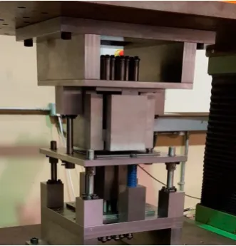
[image:3.544.189.355.119.292.2]In order to make pre-adjustment the height of pins more conveniently, 3D printed sample parts with identical curved surfaces were used as reference surfaces to align the pin heights. This approach represents an economic and fast way to pre-set the pin heights to match representing surface contours.
Fig. 1. Multi-point forming test rig used for experiment reported.
Table 1. Main material/process/tool variables
Blank Material Lubrication Rubber thickness Spring strength Curved surface depth formed
[+] Aluminum [+] Applied [+] 8 mm [+] 8.79 daN/mm [+] 16 mm [-] Steel [-] Not applied [-] 4 mm [-] 3.8 daN/mm [-] 8 mm
The holding force was varied by varying holding springs, with the spring strength of 8.79 daN/mm and 3.8 daN/mm respectively used. The holding springs were pressed and holding force increased during the process. A type of multi-purposes cutting oil was applied to the interfaces between the blank and the die-plate for the lubrication purpose. Polyurethane with thickness of 2.0 mm and 4.0 mm were chosen as the elastic cushions with good hyper-elastic property. During the tests, both sides of the sheet plate were covered with the cushions. The main variables are given in Table.1, with plus and minus for a contrast.
Before the tests, the machine was set to the pre-defined stroke ensuring that depth of the curved surface to be controlled to enable the specific finish curvature to be achieved. Lubricating oil was cleaned after each test to ensure the similar surface contact condition to be used for a following test.
3. Results and discussion
The formed sheet metal parts were measured with a Co-ordinate Measuring Machine and the indentations on the surfaces were observed with high resolution camera. 19 x 19 evenly distributed points were measured consecutively and the co-ordinates of on specific lines were plotted to illustrate the surface curvatures. Wrinkles and indentations were observed from the photos taken by high resolution camera, indicating the relationship of these to the influences from different process and material parameters.
Since there were two different combinations for each of the five kinds of material. tooling and processing parameters, a combination of 16.0 mm curved surface depth aluminum sheet with lubrication applied, a total thickness of 8.0 mm rubber cushion, under a spring stiffness of 8.79 daN/mm for holding force, was used as the base model for each comparison group, i.e. all process variations with plus remarks. A total of 6 test sheets have been measured and the Z-axis co-ordinates across the center line profile of X-axis and Y-axis have been plotted to
4 Song Yang/ Procedia Manufacturing 00 (2018) 000–000
investigate the finish surface deformations. Taking the ideal 3D printed dome-like surface in Fig. 2 as a reference surface, in each group the shape error zerror was used to determine the difference at every contact point of the center line contour, integrating the average shape error Eerror for each metal sheet. These parameters are defined as follows, being similar to that reported in [10-12]:
3 exp
error Dtest
z
=
z
−
z
. (1)By calculating the root mean square value of error above between the 3D-printed dome-value and the test piece surface with different thicknesses, the average shape value, Eerror, can be given as:
3 exp 2
1
1 * (
N)
error i Dtest i
i
E
z
z
N
==
∑
−
, (2) [image:3.544.41.498.355.406.2]where N represents the total number of the measured points. It should be noticed since the shape error can be affected by the wrinkles, only the values of the deformed surface were calculated.
Fig. 2. 3D printed dome-like surfaces (8.0 mm and 16.0 mm depth).
3.1.Effect of blank material selection
To study the effect of the material property, the experiment was conducted using aluminium alloy and steel sheets with the thickness of 1.0 mm, under the similar conditions. Two formed metal sheet parts are shown in Fig. 3. More wrinkles and indentations were found in steel sheets as seen in Fig. 3(b), while aluminium sheets perform smoother surfaces, and these may be related to the differences of the material’s plasticity, yield strength, etc., and hence, the drawing ability of those two materials.
Fig. 4 presents the surface profiles drawn based on the points measured in the vertical direction along the centre line of X-axis and Y-axis respectively. The two profiles are similar, due to the similar plastic deformation was enabled during the experiment, which followed the profiles set by the pins. The calculated average shape error for aluminium sheets along of central line are 1.085 mm and 0.775 mm along X-axis and Y-axis respectively, while these were 1.105 mm and 1.005 mm for steel sheets. In general, these are similar, with the steel parts have slightly more shape errors, which may be counted for combined effects from the materials’ yield strength, Young’s modulus as well as deflection amount of the tooling due to the forming force difference, etc.
(a) (b)
In order to make pre-adjustment the height of pins more conveniently, 3D printed sample parts with identical curved surfaces were used as reference surfaces to align the pin heights. This approach represents an economic and fast way to pre-set the pin heights to match representing surface contours.
Fig. 1. Multi-point forming test rig used for experiment reported.
Table 1. Main material/process/tool variables
Blank Material Lubrication Rubber thickness Spring strength Curved surface depth formed
[+] Aluminum [+] Applied [+] 8 mm [+] 8.79 daN/mm [+] 16 mm [-] Steel [-] Not applied [-] 4 mm [-] 3.8 daN/mm [-] 8 mm
The holding force was varied by varying holding springs, with the spring strength of 8.79 daN/mm and 3.8 daN/mm respectively used. The holding springs were pressed and holding force increased during the process. A type of multi-purposes cutting oil was applied to the interfaces between the blank and the die-plate for the lubrication purpose. Polyurethane with thickness of 2.0 mm and 4.0 mm were chosen as the elastic cushions with good hyper-elastic property. During the tests, both sides of the sheet plate were covered with the cushions. The main variables are given in Table.1, with plus and minus for a contrast.
Before the tests, the machine was set to the pre-defined stroke ensuring that depth of the curved surface to be controlled to enable the specific finish curvature to be achieved. Lubricating oil was cleaned after each test to ensure the similar surface contact condition to be used for a following test.
3. Results and discussion
The formed sheet metal parts were measured with a Co-ordinate Measuring Machine and the indentations on the surfaces were observed with high resolution camera. 19 x 19 evenly distributed points were measured consecutively and the co-ordinates of on specific lines were plotted to illustrate the surface curvatures. Wrinkles and indentations were observed from the photos taken by high resolution camera, indicating the relationship of these to the influences from different process and material parameters.
Since there were two different combinations for each of the five kinds of material. tooling and processing parameters, a combination of 16.0 mm curved surface depth aluminum sheet with lubrication applied, a total thickness of 8.0 mm rubber cushion, under a spring stiffness of 8.79 daN/mm for holding force, was used as the base model for each comparison group, i.e. all process variations with plus remarks. A total of 6 test sheets have been measured and the Z-axis co-ordinates across the center line profile of X-axis and Y-axis have been plotted to
investigate the finish surface deformations. Taking the ideal 3D printed dome-like surface in Fig. 2 as a reference surface, in each group the shape error zerror was used to determine the difference at every contact point of the center line contour, integrating the average shape error Eerror for each metal sheet. These parameters are defined as follows, being similar to that reported in [10-12]:
3 exp
error Dtest
z
=
z
−
z
. (1)By calculating the root mean square value of error above between the 3D-printed dome-value and the test piece surface with different thicknesses, the average shape value, Eerror, can be given as:
3 exp 2
1
1 * (
N)
error i Dtest i
i
E
z
z
N
==
∑
−
, (2) [image:4.544.151.395.259.359.2]where N represents the total number of the measured points. It should be noticed since the shape error can be affected by the wrinkles, only the values of the deformed surface were calculated.
Fig. 2. 3D printed dome-like surfaces (8.0 mm and 16.0 mm depth).
3.1.Effect of blank material selection
To study the effect of the material property, the experiment was conducted using aluminium alloy and steel sheets with the thickness of 1.0 mm, under the similar conditions. Two formed metal sheet parts are shown in Fig. 3. More wrinkles and indentations were found in steel sheets as seen in Fig. 3(b), while aluminium sheets perform smoother surfaces, and these may be related to the differences of the material’s plasticity, yield strength, etc., and hence, the drawing ability of those two materials.
Fig. 4 presents the surface profiles drawn based on the points measured in the vertical direction along the centre line of X-axis and Y-axis respectively. The two profiles are similar, due to the similar plastic deformation was enabled during the experiment, which followed the profiles set by the pins. The calculated average shape error for aluminium sheets along of central line are 1.085 mm and 0.775 mm along X-axis and Y-axis respectively, while these were 1.105 mm and 1.005 mm for steel sheets. In general, these are similar, with the steel parts have slightly more shape errors, which may be counted for combined effects from the materials’ yield strength, Young’s modulus as well as deflection amount of the tooling due to the forming force difference, etc.
[image:4.544.144.436.558.672.2](a) (b)
996 Song Yang/ Procedia Manufacturing 00 (2018) 000–000 Song Yang et al. / Procedia Manufacturing 15 (2018) 992–999 5
[image:5.544.126.455.74.161.2](a) (b)
Fig.4. Z-axis direction measured profile of Aluminum and Steel parts: (a) along X-axis (b) along Y-axis.
[image:5.544.127.451.179.414.2](a) (b)
Fig.5. MPF formed aluminum parts with: (a) 16.0 mm depth curvature, and (b) 8.0 mm depth curvature.
(a) (b)
Fig.6. Z-axis direction measured profile with different curvature depths: (a) along X-axis and (b) along Y-axis.
3.2.Effect of depth of curvature formed
Fig. 5 shows the formed Aluminium sheet parts with a curvature depth of 16.0 mm and 8.0 mm respectively. The one with 8.0 mm depth shown in Fig. 5(b) has a better finish surface, regarding both wrinkles as well as indents, because more forces and deformations were applied to the sheet with the deeper curvature. The average shape error value confirmed this by giving 0.804 mm and 0.400 mm at the central line in the x direction and y direction respectively for the part (b), where these are 1.085 mm and 0.775 mm for the part (a) respectively, as illustrated in Fig. 6. Careful attention should be paid when deeper and steeper surfaces are to be formed in multi-point tooling forming while an error compensation should be considered when the pin heights are pre-set initially.
3.3.Effect of thickness of elastic rubber cushion
During the multi-point forming process, elastic rubbers have been used between the pin tools and the sheets to reduce the dimples and indentations. More indentations can be observed for the sheet part with a total of 4.0 mm thick cushions, as shown in Fig.7(b), comparing to that with 8.0mm thick cushion (shown in Fig. 7(a)), this showing that increasing the thickness of the cushion could reduce the occurrence of surface indents. Nevertheless, shallow wrinkles were still found on the both sheet parts, since the cushions did not cover the blank-holding areas. Fig.8 also illustrate that the center profile corresponding to the 8.0 mm cushion is slightly larger in off-line than that with 4.0 mm, this may be due to a larger forming force applied to achieve a similar shape while the cushion is thicker and the tools were deflected more.
6 Song Yang/ Procedia Manufacturing 00 (2018) 000–000
(a) (b)
Fig.7. Part formed using: (a) 8.0 mm thick rubber and (b) 4.0 mm thick rubber.
(a) (b)
Fig.8. Z-axis direction measured profiles for two different rubber thicknesses: (a) along X-axis and (b) along Y-axis.
(a) (b)
Fig.9. Parts formed with different spring stiffness values: (a) 8.79 daN/mm and (b) 3.8 daN/mm.
(a) (b)
(a) (b)
Fig.4. Z-axis direction measured profile of Aluminum and Steel parts: (a) along X-axis (b) along Y-axis.
[image:6.544.115.435.217.311.2](a) (b)
Fig.5. MPF formed aluminum parts with: (a) 16.0 mm depth curvature, and (b) 8.0 mm depth curvature.
(a) (b)
Fig.6. Z-axis direction measured profile with different curvature depths: (a) along X-axis and (b) along Y-axis.
3.2.Effect of depth of curvature formed
Fig. 5 shows the formed Aluminium sheet parts with a curvature depth of 16.0 mm and 8.0 mm respectively. The one with 8.0 mm depth shown in Fig. 5(b) has a better finish surface, regarding both wrinkles as well as indents, because more forces and deformations were applied to the sheet with the deeper curvature. The average shape error value confirmed this by giving 0.804 mm and 0.400 mm at the central line in the x direction and y direction respectively for the part (b), where these are 1.085 mm and 0.775 mm for the part (a) respectively, as illustrated in Fig. 6. Careful attention should be paid when deeper and steeper surfaces are to be formed in multi-point tooling forming while an error compensation should be considered when the pin heights are pre-set initially.
3.3.Effect of thickness of elastic rubber cushion
During the multi-point forming process, elastic rubbers have been used between the pin tools and the sheets to reduce the dimples and indentations. More indentations can be observed for the sheet part with a total of 4.0 mm thick cushions, as shown in Fig.7(b), comparing to that with 8.0mm thick cushion (shown in Fig. 7(a)), this showing that increasing the thickness of the cushion could reduce the occurrence of surface indents. Nevertheless, shallow wrinkles were still found on the both sheet parts, since the cushions did not cover the blank-holding areas. Fig.8 also illustrate that the center profile corresponding to the 8.0 mm cushion is slightly larger in off-line than that with 4.0 mm, this may be due to a larger forming force applied to achieve a similar shape while the cushion is thicker and the tools were deflected more.
(a) (b)
Fig.7. Part formed using: (a) 8.0 mm thick rubber and (b) 4.0 mm thick rubber.
[image:6.544.127.421.339.457.2](a) (b)
Fig.8. Z-axis direction measured profiles for two different rubber thicknesses: (a) along X-axis and (b) along Y-axis.
[image:6.544.117.431.487.579.2]
(a) (b)
Fig.9. Parts formed with different spring stiffness values: (a) 8.79 daN/mm and (b) 3.8 daN/mm.
(a) (b)
998 Song Yang et al. / Procedia Manufacturing 15 (2018) 992–999
Song Yang/ Procedia Manufacturing 00 (2018) 000–000 7
[image:7.544.136.444.72.293.2](a) (b)
Fig.11. Parts formed with conditions: (a) lubricant applied (b) no lubricant applied.
(a) (b)
Fig.12. Z-axis direction measured profile with and without lubrication: (a) along X-axis and (b) along Y-axis.
3.4.Effect of holding force
The effect of the holding force was examined through the reaction force on the supporting springs with different stiffness values. The sliding of the blank material was restrained during the forming in order to achieve better drawn parts. The photos shown in Fig. 9 demonstrate the importance of using correct holding force to reduce or eliminate the occurrence of wrinkles along the flanges of workpiece while the surface quality of the drawn part could also be improved (Figs. 9 and 10). At the same time, overstretching the sheet metal should also be avoided in order to reduce the fractures to develop in the indented areas, if the cushion is to be used is too thin. This shows that an optimal combination of the material, tooling and process parameters is needed for a particular part to be formed. It is especially the case for forming of thinner sheet metals and with relatively large pin-tool sizes when miniature components are to be formed. The pin-size will be restrained not to be too small due to the manufacture and assembly considerations, even the part-size to be small is required.
3.5.Effect of lubrication condition
A multi-purpose cutting oil was used to perform lubrication between the blank and die-plate. It looks that the wrinkles could be slightly reduced at the edge due to using the lubricant (Fig. 11), which may be due to more uniform holding force is applied onto the blank. It may also be affected by the surface quality of the blank and the die-plate the condition of which could be improved by introducing a lubricant. The influence seems not to be too significant in the dome area formed since no lubricant was applied to the area (Fig. 12). The average shape error is similar but slightly reduced under the lubricating condition, from 1.090 mm to 1.085 mm in the x direction and 0.982 mm to 0.775 mm in the y direction, which may be due to the reduction of the forming force when the lubricant was applied.
4. Conclusions
Combining deep drawing and multi-point tooling has been tested for the forming miniature sized, thin metal parts with a view to extending merits of the multi-point tooling forming technique for sheet metal forming. The following conclusions may be drawn from the study described above:
8 Song Yang/ Procedia Manufacturing 00 (2018) 000–000
• Combining multi-points tooling into a deep drawing process could potentially bring benefits for process and tool flexibility for deep drawing. But the quality control has to be addressed as an important issue since the sheet metal deformation mechanism becomes more complex.
• For the process configuration tested, under the similar conditions, a better surface finish was achieved for the aluminium sheets, comparing to that for the steel sheets. This may be due to that the drawing force applied through the multi-punches used for the forming of the aluminium sheets was relatively smaller than that for the steel sheets.
• The depth of the curvature to be formed has a significant effect on the surface finish, i.e. wrinkles and indents may occur where large or steep deformations take place. The average shape-error was reduced significantly from 1.085 mm and 0.775 mm in X and Y axis directions, respectively, when 16.0 mm curvature depth was formed, to 0.804 mm and 0.400 mm respectively, when 8mm depth formed.
• Using cushions is extremely important for forming thin sheet metal parts when multi-points tooling is used, which is even more important when it is used in deep drawing due to the deeper curvatures being formed, comparing to simple bending and low-level deformation stamping involving multi-point tooling.
• As a common knowledge, correct holding force is important for deep drawing. It can, nevertheless, be said to be crucial for ensuring a high quality product, considering that the contacts between the punches and the sheet metal are not uniformly distributed, even the cushions have been used, which leads to more complex stretching and local deformation mechanisms.
• Using lubrication could help to improve the material flow and to reduce the forming force requirement. The tested cases show that an average shape-error 0.108 mm and 0.31 mm reduction achieved along the two central lines for the 16.0 mm depth curved surface formed, when a lubrication oil was introduced, comparing to that with non-oil used.
• Using 3D printing to create a model sample part to help pre-setting the multi-points tooling is an efficient approach for practical uses for multi-points tooling forming.
Further tests on the different part-geometries and materials will be conducted, with focus on the thinner sheet-metals and small sized components. The aim is to produce a design and manufacturing guideline for the forming of such types of components with deep drawing with a flexible tooling configuration.
References
[1] N. Nakajima, Research on die and electrode by steel wire bind, Japanese Journal of Mechanical Academy, 72 (1969) 32–40.
[2] F. Nishioka, An automatic bending of plates by the universal press with multiple piston heads (Second report: practicality researcher), Journal of the Society of Naval Architects of Japan, 133 (1973) 291–305.
[3] R.D. Webb, E.H. David, A transfer function description of sheet metal forming for process control, Journal of engineering for industry, 113-1 (1991) 44–52.
[4] Walczyk, F. Daniel, E.H. David, Design and analysis of reconfigurable discrete dies for sheet metal forming, Journal of Manufacturing Systems, 17-6 (1998) 436.
[5] M.Z. Li, K. Nakamura, S. Watanabe, Study of the basic principles (first report: research on multi-point forming for sheet metal), Proceedings of the Japanese Spring Conference for Technology of Plasticity, (1992) 519–522.
[6] M.Z. Li, C.G. Liu, Q.M. Chen, Research on multi-point forming of three-dimensional sheet metal parts, Advanced Technology of Plasticity, (1999) 189–194.
[7] M.Z. Li, Multi-point forming: a flexible manufacturing method for a 3-d surface sheet, Journal of Materials Processing Technology, 87-1-3 (1999) 277–280.
[8] M.Z. Li, Multi-point forming technology for sheet metal, Journal of Materials Processing Technology, 129-1-3 (2002) 333–338.
[9] M. Abosaf, Optimisation of multi-point forming process parameters, The International Journal of Advanced Manufacturing Technology, 92-5-8 (2017) 1849–1859.
[10] B.B. Jia, W.W. Wang, Shape accuracy analysis of multi-point forming process for sheet metal under normal full constrained conditions, International Journal of Material Forming, (2017) 1–11.
[11] Q.F. Zhang, Springback compensation method for doubly curved plate in multi-point forming, Materials & Design, 47 (2013) 377–385. [12] Z.Y. Cai, Numerical simulation for the multi-point stretch forming process of sheet metal, Journal of materials processing technology, 209-1
(a) (b)
Fig.11. Parts formed with conditions: (a) lubricant applied (b) no lubricant applied.
(a) (b)
Fig.12. Z-axis direction measured profile with and without lubrication: (a) along X-axis and (b) along Y-axis.
3.4.Effect of holding force
The effect of the holding force was examined through the reaction force on the supporting springs with different stiffness values. The sliding of the blank material was restrained during the forming in order to achieve better drawn parts. The photos shown in Fig. 9 demonstrate the importance of using correct holding force to reduce or eliminate the occurrence of wrinkles along the flanges of workpiece while the surface quality of the drawn part could also be improved (Figs. 9 and 10). At the same time, overstretching the sheet metal should also be avoided in order to reduce the fractures to develop in the indented areas, if the cushion is to be used is too thin. This shows that an optimal combination of the material, tooling and process parameters is needed for a particular part to be formed. It is especially the case for forming of thinner sheet metals and with relatively large pin-tool sizes when miniature components are to be formed. The pin-size will be restrained not to be too small due to the manufacture and assembly considerations, even the part-size to be small is required.
3.5.Effect of lubrication condition
A multi-purpose cutting oil was used to perform lubrication between the blank and die-plate. It looks that the wrinkles could be slightly reduced at the edge due to using the lubricant (Fig. 11), which may be due to more uniform holding force is applied onto the blank. It may also be affected by the surface quality of the blank and the die-plate the condition of which could be improved by introducing a lubricant. The influence seems not to be too significant in the dome area formed since no lubricant was applied to the area (Fig. 12). The average shape error is similar but slightly reduced under the lubricating condition, from 1.090 mm to 1.085 mm in the x direction and 0.982 mm to 0.775 mm in the y direction, which may be due to the reduction of the forming force when the lubricant was applied.
4. Conclusions
Combining deep drawing and multi-point tooling has been tested for the forming miniature sized, thin metal parts with a view to extending merits of the multi-point tooling forming technique for sheet metal forming. The following conclusions may be drawn from the study described above:
• Combining multi-points tooling into a deep drawing process could potentially bring benefits for process and tool flexibility for deep drawing. But the quality control has to be addressed as an important issue since the sheet metal deformation mechanism becomes more complex.
• For the process configuration tested, under the similar conditions, a better surface finish was achieved for the aluminium sheets, comparing to that for the steel sheets. This may be due to that the drawing force applied through the multi-punches used for the forming of the aluminium sheets was relatively smaller than that for the steel sheets.
• The depth of the curvature to be formed has a significant effect on the surface finish, i.e. wrinkles and indents may occur where large or steep deformations take place. The average shape-error was reduced significantly from 1.085 mm and 0.775 mm in X and Y axis directions, respectively, when 16.0 mm curvature depth was formed, to 0.804 mm and 0.400 mm respectively, when 8mm depth formed.
• Using cushions is extremely important for forming thin sheet metal parts when multi-points tooling is used, which is even more important when it is used in deep drawing due to the deeper curvatures being formed, comparing to simple bending and low-level deformation stamping involving multi-point tooling.
• As a common knowledge, correct holding force is important for deep drawing. It can, nevertheless, be said to be crucial for ensuring a high quality product, considering that the contacts between the punches and the sheet metal are not uniformly distributed, even the cushions have been used, which leads to more complex stretching and local deformation mechanisms.
• Using lubrication could help to improve the material flow and to reduce the forming force requirement. The tested cases show that an average shape-error 0.108 mm and 0.31 mm reduction achieved along the two central lines for the 16.0 mm depth curved surface formed, when a lubrication oil was introduced, comparing to that with non-oil used.
• Using 3D printing to create a model sample part to help pre-setting the multi-points tooling is an efficient approach for practical uses for multi-points tooling forming.
Further tests on the different part-geometries and materials will be conducted, with focus on the thinner sheet-metals and small sized components. The aim is to produce a design and manufacturing guideline for the forming of such types of components with deep drawing with a flexible tooling configuration.
References
[1] N. Nakajima, Research on die and electrode by steel wire bind, Japanese Journal of Mechanical Academy, 72 (1969) 32–40.
[2] F. Nishioka, An automatic bending of plates by the universal press with multiple piston heads (Second report: practicality researcher), Journal of the Society of Naval Architects of Japan, 133 (1973) 291–305.
[3] R.D. Webb, E.H. David, A transfer function description of sheet metal forming for process control, Journal of engineering for industry, 113-1 (1991) 44–52.
[4] Walczyk, F. Daniel, E.H. David, Design and analysis of reconfigurable discrete dies for sheet metal forming, Journal of Manufacturing Systems, 17-6 (1998) 436.
[5] M.Z. Li, K. Nakamura, S. Watanabe, Study of the basic principles (first report: research on multi-point forming for sheet metal), Proceedings of the Japanese Spring Conference for Technology of Plasticity, (1992) 519–522.
[6] M.Z. Li, C.G. Liu, Q.M. Chen, Research on multi-point forming of three-dimensional sheet metal parts, Advanced Technology of Plasticity, (1999) 189–194.
[7] M.Z. Li, Multi-point forming: a flexible manufacturing method for a 3-d surface sheet, Journal of Materials Processing Technology, 87-1-3 (1999) 277–280.
[8] M.Z. Li, Multi-point forming technology for sheet metal, Journal of Materials Processing Technology, 129-1-3 (2002) 333–338.
[9] M. Abosaf, Optimisation of multi-point forming process parameters, The International Journal of Advanced Manufacturing Technology, 92-5-8 (2017) 1849–1859.
[10] B.B. Jia, W.W. Wang, Shape accuracy analysis of multi-point forming process for sheet metal under normal full constrained conditions, International Journal of Material Forming, (2017) 1–11.
[11] Q.F. Zhang, Springback compensation method for doubly curved plate in multi-point forming, Materials & Design, 47 (2013) 377–385. [12] Z.Y. Cai, Numerical simulation for the multi-point stretch forming process of sheet metal, Journal of materials processing technology, 209-1