Peridynamics for predicting pit-to-crack transition
Dennj De Meo1 , Luigi Russo2, and Erkan Oterkus3 The University of Strathclyde, Glasgow, G4 0LZ, UK
and
Dayalan Gunasegaram4 and Ivan Cole5 CSIRO Manufacturing, Clayton, VIC, 3169, Australia
Even though the failure mechanisms in aerospace structures are mainly governed by the incidence of fatigue loading, environmentally assisted fracture related pit-to-crack transition can still occur in many aluminum alloys, stainless steels and high strength low alloy steels. Despite of the relative rarity of this phenomenon, the consequent failures can be extremely destructive and lead to the loss of an aircraft. Prediction of damage evolution starting at corrosion pits acting as precursor to cracking has been hampered by a lack of insight into the process, as well as limitations in visualization and measurement techniques. In this regard, numerical modeling can be beneficial. The current study presents numerical predictions of pit evolution from a flat metal surface to realistic pit morphologies by using a new continuum mechanics formulation, peridynamics. Intergranular/transgranular pit-to-crack transition under different loading conditions and microstructural features are investigated without imposing any limiting assumption on the site of the crack initiation. Based on the numerical results, it can be concluded that microstructure has a significant effect for the prediction of pit-to-crack transition phenomenon.
I.
Introduction
Even though the failure mechanisms in aerospace structures are mainly governed by the incidence of fatigue loading, environmentally assisted fracture (EAF) related pit-to-crack transition can still occur in many aluminum alloys, stainless steels and high strength low alloy steels. Moreover, presence of corrosion damage can reduce the fatigue life of the structure [1]. Despite of the relative rarity of this phenomenon, the consequent failures can be extremely destructive and lead to the loss of an aircraft. In February 1992, a military jet crashed in the Dutch city of Hengelo because of a localized corrosion and subsequent EAF of the lever-arm-pin in the jet engine made of austenitic stainless steel [2]. Another relevant incident, which can be attributed to corrosion pitting followed by EAF occurred in February 2007 on the left side of helicopter main landing gear drag beam made of ultrahigh strength steel during landing operations [2].
Prediction of damage evolution starting at corrosion pits acting as precursor to cracking has been hampered by a lack of insight into the process, as well as limitations in visualization and measurement techniques. For long cracks, standards for quantifying environment-assisted crack growth rates can be found [3]. However, in relation to the growth rate of small cracks emerging from corrosion pits, there are no such standards available to guide the measurement process. In this regard, numerical modeling can be beneficial. Nonethless, it is presently hampered by the popular assumption [3] that the crack has the same depth as the pit at the point of transition and initiates at the pit base, as it has no intrinsic foundation. In fact, novel observations using X-ray tomography of stress-corrosion cracks
1
PhD Researcher, Department of Naval Architecture, Ocean, and Marine Engineering. 2 PhD Researcher, Department of Naval Architecture, Ocean, and Marine Engineering.
3 Associate Professor, Department of Naval Architecture, Ocean, and Marine Engineering, AIAA Member. 4
Principal Research Engineer/Scientist, CSIRO Manufacturing
emerging from pits showed that cracks evolved from the pit predominantly at or near the pit mouth and not at the pit base [4]. Moreover, recent finite element analysis of pits in specimens subjected to different static loads revealed that maximum stress and strain can occur at the pit shoulder and in the proximity to the pit mouth [5]. The current study presents numerical predictions of pit evolution from a flat metal surface to realistic pit morphologies by using a new continuum mechanics formulation, peridynamics. Intergranular/transgranular pit-to-crack transition under different loading conditions and microstructural features are investigated without imposing any limiting assumption on the site of the crack initiation.
II.
Peridynamics
An alternative to traditional finite element analysis (FEA) is the peridynamic (PD) theory introduced by Silling [6]. FEA is based on classical continuum mechanics which is using partial differential equations to describe the motion of material points. On the other hand, PD is a nonlocal extension of classical continuum mechanics that is based on integro-differential equations involving time and spatial coordinates. This feature allows damage initiation and propagation at multiple sites with arbitrary paths inside the material without resorting to special crack growth criteria. In the PD theory, internal forces are expressed through nonlocal interactions between pairs of material points within a continuous body, and damage is part of the constitutive model.
PD theory was successfully applied for the first time by De Meo et al. [7] to model stress-corrosion cracking (SCC) damage in polycrystalline materials due to hydrogen embrittlement. As an extension of that work, the present study focuses on the transition from corrosion pits to cracks due to EAF. Thus, a new PD algorithm, based on implicit time integration, has been introduced for predicting metal dissolution. This process is modeled using a modified Nernst-Planck equation, where electromigration and diffusion effects are included in an effective diffusion coefficient, whose value is obtained through calibration against experimental data as explained in [8]. The peridynamics version of the governing equation for metal dissolution can be written as:
( , ) d
, , , , , , d HC t C t t
C t
f Vx
x x x x
x x' (1)
where C( , )xt is the time derivative of metal ion concentration associated with the generic material point x, and
d C , ,t C , , , ,t t
f x x x x is called metal dissolution response function which is defined as:
fd dC( , ) t C( , )t
x x
x x
(2)
in which the peridynamic diffusion bond constant dcan be expressed in terms of the effective diffusion coefficient eff
D as:
d 6 Deff3 h
(3)
concentration of C = 0 mol/m3 is applied as a boundary condition in the middle of the top surface to a scratch in the oxide film with a length of 6 μm. At the beginning of the simulation, all nodes belonging to the metal have a concentration of metal ions equal to Csolid = 143000 mol/m3. As soon as the concentration valuesdrop below the saturation value of the concentration of metal ions in the corrosive solution, Csat = 5100 mol/m3, the related nodes are considered as belonging to the liquid region. The diffusivities of metal ions in the solid and liquid regions are specified as dsolid = 210-12 m2/s and dliquid = 8.510-10 m2/s , respectively.
The plate is discretized with 100 100, 200 200 and 300 300 PD nodes and the resulting value of grid spacing and horizon radius values are = 1 m, 0.5 m, 0.3333 mand = 3 m, 1.5 m, 1 m, respectively. The total time is specified as t = 500 s.
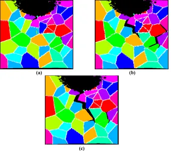
Concerning the second phase of the analysis, i.e., crack propagation, the microstructure of the material is constituted of 50 randomly oriented crystals and the following values of material constants, density and fracture toughness of the material are considered: c11 = 204.6 GPa, c12 = 137.7 GPa, = 7880 kg/m3 and KIc = 70 MPam1/2, respectively [9]. A horizontal velocity boundary condition of 0.2 m/s is applied along the left and right edges of the plate. Moreover, the vertical displacement of the nodes in this region is constrained along the vertical direction. The total time is t = 15 s. The time step size has to be small enough to capture the full dynamic characteristic of the problem and different time step sizes, dt = 0.05 s, 0.1 s and 0.5 s are considered to perform a convergence analysis. To model intergranular fracture, only the bonds crossing the grain boundary of the crystals are allowed to break whereas twice stronger grain boundaries with respect to grain interiors are considered for transgranular fracture.
(c)
Figure 1. Pit-to-crack transition (100 100 particles, t = 15 µs, dt = (a) 0.05 µs, (b) 0.1 µs, (c) 0.5 µs)
(a) (b)
(c)
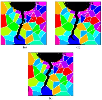
[image:4.612.142.485.268.571.2]Figure 3. Pit-to-crack transition (300 300 particles, t = 15 µs, dt = 0.1 µs)
For the intergranular case, based on the results shown in Figures 1-3 for different discretization sizes and time increments, it can be concluded that the crack initiation takes place from the pit base for the randomly generated microstructure.
(a) (b)
(c)
[image:5.612.140.473.280.586.2](a) (b)
[image:6.612.143.471.67.387.2](c)
Figure 5. Pit-to-crack transition (200 200 particles, t = 15 µs, dt = (a) 0.05 µs, (b) 0.1 µs, (c) 0.5 µs)
(a) (b)
[image:6.612.144.469.432.586.2]are investigated and different crack initiation locations are predicted. Hence, it can be concluded that microstructure has a significant effect for the prediction of pit-to-crack transition phenomenon.
References
[1] S. H. Spence, N. M. Williams, A. Stonham, M. R. Bache, A. R. Ward, W. J. Evans, D. Hay, C. Urbani, B. R. Crawford, C. Loader and G. Clark, Fatigue in the presence of corrosion pitting in an aerospace aluminum alloy, 2002, Proccedings of the Eighth International Fatigue Congress, vol. 1, pp. 701-708.
[2] R. J. H. Wanhill, R. T. Byrnes, and C. L. Smith, Stress corrosion cracking (SCC) in aereospace vehicles, 2011, Woodhead
Publishing, pp. 608-650.
[3] Turnbull, A., Corrosion pitting and environmentally assisted small crack growth, 2014, Proc. R. Soc. A 470: 20140254.
[4] Turnbull, A., Wright, L., and Crocker, L., New insight into the pit-to-crack transition from finite element analysis of the stress and strain distribution around a corrosion pit, 2010, Corros. Sci., vol. 52(4), pp.1492–1498.
[5] Zhu, L. K., Yan, Y., Qiao, L. J. and Volinsky, A. A., Stainless steel pitting and early-stage stress corrosion cracking under ultra-low elastic load, 2013, Corros. Sci., vol. 77, pp.360–368.
[6] S. A. Silling, Reformulation of elasticity theory for discontinuities and long-range forces, 2000, J. Mech. Phys. Solids, vol.
48, pp. 175–209.
[7] D. De Meo, C. Diyaroglu, N. Zhu, E. Oterkus, and M. Amir Siddiq, Modelling of stress-corrosion cracking by using
peridynamics, 2016, Int. J. Hydrogen Energy, vol. 41, pp. 6593–6609.
[8] Z. Chen and F. Bobaru, Peridynamic modeling of pitting corrosion damage, 2015, J. Mech. Phys. Solids, vol. 78, pp. 352–
381.