International Journal of Innovative Technology and Exploring Engineering (IJITEE) ISSN: 2278-3075, Volume-8 Issue-10, August 2019
Design and Finite Element analysis of Thick walled
Laminated Composite Pressure Vessel
Sarada Prasad Parida, Pankaj Charan Jena
Abstract: Composite materials in general offer a high potential for manufacturing of structures with featuring an interesting mechanical performance, mainly with regards to specific stiffness, specific strength, damage tolerance and energy absorption capability. In current analysis, glass fibre reinforced in epoxy resin to form a laminated composite walled pressure vessel(filament winding) is considered for design. The purpose of this work is primarily to perform finite element analysis (FEA) of a composite walled pressure vessel (CPV) under different loads. Different design stresses and strains are evaluated using Lame’s equation. These outcomes are tabulated and examined with the results of the steel walled pressure vessel used for LPG. It is foundthat CPV is a suitable vessel for LPG storage and it can be replaced current LPG steel walled vessel to CPV.
Keyword: design, cylinder, composite walled, vessel
FR Normal force along radial direction
Fϴ Normal force along Tangential l direction
FRϴ Shear force
MR Bending moment along radial direction
Mϴ Bending moment along Tangential direction
MRϴ Bending moment along Rϴ plane
σRR Radial stress
σϴϴ Tangential stress
σRϴ Shear stress k
z
Thickness of kth layer1
k
z
Thickness of k-1 th layer n Number of layer0 ,
[
]
R Normal strain component matrix,
[ ]
R Shear strain component matrixqrr, qss,
qϴϴ, qrϴ,
qrs, qϴs
Transformed stiffness of orthotropic composite cylinders in respective R, S, ϴ directions
qij stiffness of individual lamina in i and j directions
[A],[B],[D] Components of compliance matrix
E1,E2 Modulus of elasticity of individual lamina along warp and fill direction
G12 Modulus of rigidity
12 21
Poisions ratio along warp and fill directionP Internal pressure
Ro Outer diameter
Ri Inner diameter
H Wall thickness
Poisons ratioR
Radial displacementRevised Manuscript Received on July 22, 2019.
* Correspondence Author: Pankaj Charan Jena
Sarada Prasad Parida, Department of Production Engineering at Veer Surendra Sai University of Technology, Burla, Odisha, India,
sarada800@gmail.com
Pankaj Charan Jena *, Department of Production Engineering at Veer Surendra Sai University of Technology, Burla, Odisha, India-768018, E-mail: pankajcharanjena@gmail.com
I. INTRODUCTION
Composite materials in general offer a high potential for manufacturing of structures featuring an interesting mechanical performance, mainly with regard to specific stiffness, specific strength, damage tolerance and energy absorption capability Composite pressure vessels were originally developed for aerospace applications. Nowadays, these are utilized in broad field of applications such as water treatment stations and petroleum industry. The current state of the art composite pressure vessels are light, safe.
The purpose of this work is primarily to perform finite element study of composite pressure vessel subjected to various constraints of loads and to investigate the possibility of replacing current LPG steel vessels with cpvs. The analysis is carried out using the finite element method.
Guz et al.[14] reviewed the practical applications of thick composite pipes subjected to outer pressure in oil and gas industry and analytically demonstrated the failure analysis by stress distribution through the wall thickness for different lay ups of fibres. Davies et al. [14] demonstrated the use of glass/epoxy and carbon/epoxy composite pressure vessel in underwater applications with implosion pressure of 600bar in 6000m depth. Ahmad and Hoa[15] experimentally determined the flexural stiffness of thick walled tubes indigenously manufactured by fiber placement machine. Ahmadi [16] used Reddy’s layer wise theory and approached an analytical method to determine inter-laminar stresses from elastic equations subjected to uniform and non-uniform internal pressure. Ramos et al. [17] studied the mechanical behaviour of thick anisotropic fiber reinforced composite cylinder analytically by exact 3-D elastic solution approach and the results obtained were compared with the results of FEA study. Arhant et al. [18] designed and fabricated thermoplastic composite pressure vessels and presented that thermoplastic composites pressure vessels in undersea application can be the replacements of thermoset composites. For validity of the result the experimental data are matched with the results obtained from FEA study for different stacking sequence of fiber and internal pressure.
II. MODELLINGOFTHICKWALLEDCYLINDERS
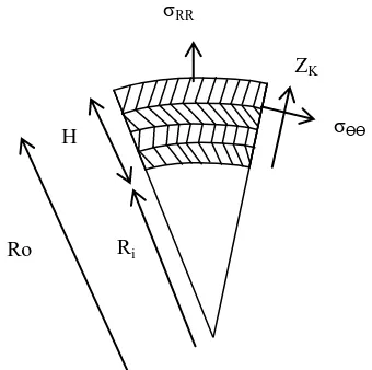
[image:2.595.308.509.60.418.2]The pressurevessels or gas cylinders which are generally used for storing fluids i.e. liquid or gas under pressure are of thick cylinders. In this case the cylinder wall is taken as of four layered composite material. The whole procedure of study is presented through the following flow chart (Figure1). The stress strain relationship for an orthotropic composite material can be determined using laminated shell theory. Shells are three dimensional bodies closed by curved surface as shown in the Figure 2.
[image:2.595.331.501.455.624.2]Table-I: Elastic Properties of Epoxy –Glass
Fig 1: Detail steps of current analysis in flow chart.
Fig 2: Schematic view of orthotropic composite walled cylinder.
1 1
k
R n n R
I Z
R R
F
F
zdz
F
(1)
Material Properties Values
Glass fiber
Fiber longitudinal modulus in l direction Efl(GPa)
78
Fiber transverse modulus in t direction EftGPa
78
Fiber shear modulus Gf (Gpa) 30
Density ρf (kg/m3) 2650
Fiber Poisson ratio νfℓt 0.3
Epoxy resin
Elastic modulus E (Gpa) 4
Shear modulus G (Gpa) 1.43
Density ρm(kg/m3) 1250
Poisson ratio ν 0.4
σϴϴ σRR
H
ZK
[image:2.595.41.287.505.655.2]International Journal of Innovative Technology and Exploring Engineering (IJITEE) ISSN: 2278-3075, Volume-8 Issue-10, August 2019
1 1
kR n n R
I Z R R
M
M
zdz
M
(2) 1 1 0, 1 ,
,
2 2 0
1 , ,
[ ]
[ ]
(
)
1
[ ]
(
)
2
k k k kR k k R
R k k k
k k R
R k
F
q
z
z
q
z
z
(3) 0
,
[ ]
,[
]
,[ ]
,[ ]
,
F
R
A
R RB
Rk
R (4)0
,
[ ]
,[
]
,[ ]
,[ ]
,
M
R
B
R RD
Rk
R (5)The laminate compliance matrix is given
by
1
1
n k
ij ij k k k
A
q
z
z
(6)
2 2
1 1
1
2
n kij ij k k
k
B
q
z
z
(7)
3 3
1 1
1
3
n kij ij k k
k
D
q
z
z
(8)where
4 4 2 2 2 2
11 22
2
124
66RR
q
c q
s q
c s q
c s q
4 4 2 2 2 2
11 22
2
124
66q
s q
c q
c s q
c s q
3 3 2 2
11 22 12
2 2
12 66
(
)
2 (
)
Rs
q
c sq
s cq
cs c
s q
cs c
s q q
2 2 2 2 2 2
11 22 12
2 2
12 66
2
(
)
ss
q
c s q
c s sq
c s sq
c
s q q
3 3 2 2
11 22 12
2 2
12 66
(
)
2 (
)
s
q
s cq
c sq
cs c
s q
cs c
s q q
1 11 12 21
1
E
q
2 22 12 21 1 E q
21 1 12 2
12 21
12 21 12 21
1
1
E
E
q
q
66 12
q
G
0
a
b
F
c
d
M
k
1
* * 1
*a
A
B
D
C
* 1b
B
D
* 1 *c
D
C
* 1d
D
1
*
B
A
B
1 *C
B
A
1
*
D
D
B
A
B
In this case the composite cylinder is of four layers of lamina. Hence it may be assumed as a thick composite cylinder. The tangential and radial stresses components may be written using lames equation as;
2 2 2
2 2 2 2 2
i o i
o o o o
R R
P
PR
z
R
R
R
R
(9)2 2 2
2 2 2 2 2
i i o
RR
o i o i
PR
R R
P
R
R
z
R
R
(10)2 2 2 o R o i
PR
R
R
Maximum wall thickness is given by
1
iP
H
R
P
(11)Also the strain displacement relationship for a thick cylinder can be expressed as
2 2 1 2 2 1 1 2 2 1 2 2 1 1
1
1
k i i R Oi i i i
k
i i
O
i i i i
R
R
PR
E
R
R
R
R
PR
E
R
R
(12)III. NUMERICALMODELLING
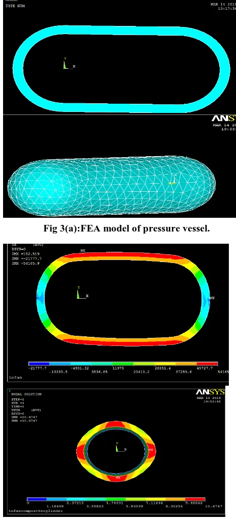
Fig 3(a):FEA model of pressure vessel.
Fig3(b): Shows the radial displacements of FEA models of Pressure vessel.
IV. RESULT AND DISCUSSION
For the comparative study of the steel thick cylinder with the composite cylinder, an internal pressure of 120MPa is taken. Also, it is tried to find the best configuration of the fibre orientation among the designed four fiber orientations of 0º,45º and 90º the composite cylinders from here known as the sample cylinders and are presented in the Table. The results obtained are presented in Table-II.
The variation of hoop stress, radial stress, major principal stress, minor principal stress, resultant stress intensity and von misses stress intensity for the thick cylinders of different composite sample cylinder and steel cylinder subjected to 120MPa internal pressure are presented in Fig.4. From the
[image:4.595.46.282.50.275.2]higher properties than the other test specimens in all aspect of the study. However from other four composite cylinders sample-4 having ±(0 º /90 º) fibre orientation has superior property with less stress intensity. So the composite cylinder with ±(0 º /90 º) may be taken for the study.
Fig. 4: variation of stress for different cylinder samples. Fig.5 represents the longitudinal displacement of four composite cylinders samples along with the thick-walled steel cylinder. From the graph it can be observed that all of the samples are nearly equal longitudinal displacement. Hence the effect of fibre orientation does not play any important role on longitudinal displacement of the cylinders. Change of internal pressure also causes the change in observed stress parameters and longitudinal displacement of the thick cylinders. For the study the internal pressures are varied from 100MPa to 170MPa and the change in stress values and longitudinal displacement of thick steel cylinder and composite cylinder are determined. Figure 6and Figure 7represent the variation of hoop stress, longitudinal stress, three mutual principal stresses, resultant stress intensity and von misses stress intensity with change in internal pressures from 100MPa to 170MPa for steel cylinder and composite cylinder. From both of the graph it is quite clear that with increase in internal pressure different types of stresses developed inside the cylinder also increases. However, von misses stress intensity increases rapidly or more exponentially than other stress components.
[image:4.595.44.276.57.568.2] [image:4.595.306.547.112.266.2]International Journal of Innovative Technology and Exploring Engineering (IJITEE) ISSN: 2278-3075, Volume-8 Issue-10, August 2019
Fig.6: variation of internal pressure on steel cylinder.
Fig.7: variation of stresses with internal pressure of composite cylinder.
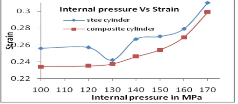
[image:5.595.314.549.51.186.2]Figure 8 represents the varation of the lpngitudinal displacement with the variationa of internal pressure both for composite cylinder and steel cylinder. From the curve it is quite clear that with increase in internal presure, longitudinal displacement increases. Also from the graph it can be seen that the longitudinal displacement increases gradully upto 130MPa internal pressure. Then further increase in internal pressure longitudinal displacement increases rapidly or exponenttially. The effect of wall thickness on the stresses developed in the cylinder subjected to 120MPa internal pressure is studied. for the study the wall thickness of the cylinders is taken as 4mm, 6mm, 8mm, 10mm, 12mm, 14mm and 16mm respectively. Figure 9 represents the variation of the different stresses namely hoop stress, longitudinal stress, major principal stress, minor principal stress, resultant stress intensity and vonmisses stress intensity of the steel cylinder with the variation of the wall thickness. It can be seen that with increase in wall thickness the value of hoop stress, longitudinal stress, principal stresses, resultant stress intensity and von misses stress intensity decreases. The same nature of variation of the stresses for the composite cylinder is presented in fig.10.
Fig.8: variation of longitudinal displacement with internal pressure.
[image:5.595.304.546.180.547.2]Fig. 9: variation of stresses with wall thickness for steel cylinder.
Fig.10: variation of stresses with wall thickness for composite cylinder.
Fig. 11: variations of stresses with wall thickness of composite cylinder. Fig.11represents the variation of the longitudinal displacement of steel and composite cylinder
[image:5.595.310.549.221.362.2] [image:5.595.304.542.336.522.2] [image:5.595.47.291.629.736.2]o
Table-II. Stresses of steel and composite cylinders. From the graph it is quite clear that with increase in wall thickness of the thick cylinder, the longitudinal displacement decreases rapidly.
Samples Stresses Developed in the Specimens
Deformatio n in mm (Δl) Normal stress in MPa Principal stresses in MPa Stress
intensity (SI) in MPa
VonMisses Stress in MPa
σθ σr σ1 σ2 σ3
Steel 72 44.5 104 31 14.2 80.67 58.5 0.03
co
m
p
o
site
sample-1(0 º /45 º)2s 58.2 34.07 62.9 27.22 11.89 67.63 58.58 0.45
sample-2± (0 º /45 º) 59.8 33.65 64.6 25.6 11.3 67.6 58.5 0.38
Sample-3(0 º /90 º)2s 65.1 42.5 70.9 33.7 12.82 67.66 57.36 0.508
Sample-4± (0 º /90 º) 63.2 41.5 68.2 32.5 13.5 66.86 57.58 0.502
IV.CONCLUSION
The steel cylinder has superior property than the composite cylinders. However, it can be observed that von misses stress intensity which plays a crucial role in the design of pressure vessel is nearly equal for the steel cylinder and all composite cylinders. But the compressive stress or hoop stress is quite lower. Also, from all of the fiber orientations taken for the study ± (0 º /90 º) lamina orientation may be considered for the study. All the test samples have negligible and nearly equal longitudinal deformation for all of the internal pressures and wall thicknesses. With increase in internal pressure the developed stress values developed inside the cylinder increases. Also, the longitudinal displacements are found to be increasing with the increase in internal pressures. Also, it is observed that with increase in the wall thickness decreases the developed stress values and longitudinal displacement.
REFERENCE
1. Tauchert, T.R. Optimum Design of A Reinforced Cylindrical Pressure Vessel, Journal of Composite Materials, 1981, 15: pp.390–402. 2. Eckold, G.C. (1985). A Design Method for Filament Wound GRP
Vessels and Pipework, Composites, 16:pp. 41–47
3. Adali, S., Sumers, E.B. and Verijenko, V.E. Optimization of Laminated Cylindrical Pressure Vessels under Strength Criterion, Composite Structures, 1993, 25(3): pp.305–312
4. Cohen D., Influence of Filament Winding Parameters on Composite Vessel Quality and Strength, Compos Part A-ApplSciManufac 1997; pp.1035-47
5. Cohen D., Mantell. S.C., Zhao. L., The Effect of Fiber Volume Fraction on Filament Wound Composite Pressure Vessel Strength.composites Part B; 32; 2001; pp.413-429
6. Xu S.Q &.Yu, M.H, “Shakedown Anaysis of thick walled cylinders subjected to internal pressure with the inified strength criterion”, International Journal of Pressure vessels & piping, 2005;Vol 82, ; pp.706-712.
7. Naser, S.A.I, and Osama, M.A.H.,Composite LPG Cylinders asan Alternative to Steel Cylinders: Finite Element Approach, International Conference on Manufacturing and Materials Processing (ICMM 2006), Kuala Lumpur, Malaysia, 2006, ; pp.363-368
8. Antunes . P. J., Dias G. R., Nunes J. P. and Van Hattum . F. W. J., Finite Element Modelling of Thermoplastic Matrix Composite Gas Cylinders, Journal of Thermoplastic Composite Materials, Vol. 21—September 2008 , ; pp. 411
9. Yue Z., Li. X., Numerical Simulation of All-Composite Compressed Natural Gas (CNG) Cylinders for Vehicle, Procedia Engineering 37 , 2012 ; pp.31 – 36
10.TaheriF. ,Advanced fiber-reinforced polymer (FRP) composites for the manufacture and rehabilitation of pipes and tanks in the oil and gas industry. In: Bai J, editor. Advanced fiber-reinforced polymer (FRP) composites for structural applications. Sawston: Woodhead Publishing Limited., 2013; pp. 662–704
11.Lepikhin, P. P. , Romashchenko, V. A. , and Bakhtina, E. V., Methods And Findings of Stress-Strain And Strength Analyses of Multilayer
(Review). Part 1. Experimental Studies, Strength of Materials, Vol. 45, No. 1, January, 2013
12.Hemmatnezhad, M., Rahimi . G.H., Tajik M., Pellicano F., Experimental, numerical and analytical investigation of free vibrational behavior of GFRP-stiffened composite cylindrical shells, Composite Structures, 120.10.1016/j.compstruct.2014.10.011. 13.Guz I.A., Menshykova M., Paik J.K., Thick-walled composite tubes for
offshore applications: an example of stress and failure analysis for filament-wound multi-layered pipes, Ships and Offshore Structures, 2015
14.Davies P., choqueuse D., Bigourdan B., Chachot P., Composite Cylinders for Deep Sea Applications: An Overview, Journal of Pressure Vessel Technology, Dec 2016, Vol. 138 / 060904-1 15.Ahmad, M.I.G., Hoa, S.V., Flexural stiffness of thick walled composite
tubes , Composite Structures, Volume 149, 1 August 2016, ; pp.125-133
16.Ahmadi, I., Interlaminar stress analysis in general thick composite cylinder subjected to nonuniform distributed radial pressure,
Mechanics of Advanced Materials and Structures , Volume 24, 2017
- Issue 9, ; pp.773-788
17.Ramos, I., Park, Y.H., Sanchez, J.U., Analytical and Numerical Studies of a Thick Anisotropic Multilayered Fiber-Reinforced Composite Pressure Vessel , J. Pressure Vessel Technology, 141(1), 011203 (Dec 07, 2018)
18.Arhant, M. ,Briancon, C., Burtin, C., Davis, P., Carbon/polyamide 6 thermoplastic composite cylinders for deep sea applications,
Composite StructuresVolume 212, 15 March 2019, ; pp.535-546.
Authors Profile
First Author
Mr. SaradaPrasad Parida is presently pursuing PhD in the Department of Production Engineering at Veer Surendra Sai University of Technology, Burla, Odisha, India. His research interest includes Mechanical Vibration, FEM and Composite Material.
Corresponding Author
Dr. Pankaj Charan Jena (Ph.D in Mechanical Engineering, aJ ,atakJaJ ,yJ sru inv rupvad
anyvJ ) vpstukvn JpcpptAvJarnutrrpptu ,
rsJuarrna
tr nutyrAavtn in vnrruvn ,
rru rrurnyuJ rJv
inv rupvadtryrAsntat d ,
aruaJ , ayvpsJ , anyvJ . vp
AruurnaurprJuAsvnarurpapvnAaryrc