Ames Laboratory ISC Technical Reports Ames Laboratory
3-20-1953
Operating characteristics of a D.C. magnetic ion
source
G. H. Miller Iowa State College R. A. Lowry Iowa State College J. E. Osher Iowa State College
Follow this and additional works at:http://lib.dr.iastate.edu/ameslab_iscreports Part of thePhysics Commons
This Report is brought to you for free and open access by the Ames Laboratory at Iowa State University Digital Repository. It has been accepted for inclusion in Ames Laboratory ISC Technical Reports by an authorized administrator of Iowa State University Digital Repository. For more information, please [email protected].
Recommended Citation
Miller, G. H.; Lowry, R. A.; and Osher, J. E., "Operating characteristics of a D.C. magnetic ion source" (1953).Ames Laboratory ISC Technical Reports. 54.
Abstract
The operating characteristics of an ion source of the type described by Kistemaker and Dekker are given. The dependence of the total ion output on the ion source pressure, magnetic field, anode voltage, filament emission, and probe voltage is described. When hydrogen gas was used the ion· source operated stably for pressures in the range of 1.5 to 2.5 microns of Hg producing maximum ion currents of 3 to 5 ma. Its gas consumption was relatively high (22.5 cc/hr, STP) and the proton percentage of the ion beam was of the order of 8%. The best focusing gave a beam diameter of 5 mm on a target 2 meters from the ion source. The filament lifetimes varied from 50 to more than 100 hours. The power consumption for ion beams of 3 ma or less was found to be about 0.15 watts/ua.
Keywords Ames Laboratory
Disciplines Physics
U N I T E D
ISC-319
STATES A T 0 M I C E N E R G Y C 0 M M I S S I 0 N
OPERATING CHARACTERISTICS OF A D.C.
MAGNETIC ION SOURCE
by
G. H. Miller, R. A. Lowry, and J. E. Osher
March 20, 1953
Ames Laboratory at
Iowa State College F. H. Spedding, Director
Contract W-7405 eng-82
2 ISC-319
I.
II.
III.
IV.
v.
VI.ABSTRACT
INTRODUCTION
TABLE OF CONTENTS
0 0 0 • • 0 0 • 0 • 0 0 • 0 • 0 • • 0 0 0 • • • • • • 0 • • 0 • • • • • • • • • • • • • •
0 • 0 0 0 • 0 • 0 0 0 0 0 • 0 0 0 0 0 0 • • 0 0 • 0 0 • 0 • • 0 0 • • • • 0 0 • 0 • • • •
DESCRIPTION OF THE ION SOURCE
PERFORMANCE
0 • • 0 0 0 • • 0 • 0 0 0 0 0 0 • 0 0 0 0 0 • 0 0 0 • 0
SUMMARY AND DISCUSSION 0 0 • 0 0 0 • 0 0 0 0 0 0 0 0 • 0 0 0 0 • • 0 0 • 0 0 • 0 • 0 0 0 • 0
LITERATURE CITED 0 0 0 0 0 0 • 0 0 0 0 0 0 0 0 0 • 0 0 0 0 0 0 0 0 0 0 0 0 0 0 • 0 0 0 0 0 0 0 0 0
PaQ:e
5
5
7
8
17
OPERATING CHARACTERISTICS OF A D.C.
MAGNETIC ION SOURCE
G. H. Miller, R. A. Lowry, and J. E. Osher
I. ABSTRACT
The operating characteristics of an ion source of the type
described by Kistemaker .and Dekker are given. The d~pendence of
the total ion output on the ion source pressure$ magnetic field,
anode voltage, filament emission$ and probe voltage is described.
When hydrogen gas was used the ion· source operated stably for pressures in the range of 1.5 to 2.5 microns of Hg producing
maxi-mum ion currents of 3 to 5 rna. Its' gas consumption was relatively
high (22.5 cc/hr, STP) and the proton percentage of the ion beam
was of the order of
8%.
The best focusing gave a beam diameter of 5 mm on a target 2 meters from the ion source. The filament lifetimes varied frorri 50 ~to more thaniOG
··hours~· !11The power-:''"''· -11consumption for ion beams of 3 rna or less was found to be about ;
0.15 watts/ua.
II. INTRODUCTION
During the last four years considerable work has been done at this laboratory on the construction of ion sources to be used
to produce protons$ deuterons, and other heavy ions for
acceler-ation by the kevatron. It is the purpose of this report to
summarize this work and to present significant results.
Some of the first work was done with a Zinn (1) type ion source. However, its construction was evidently faulty and consequently it failed to perform satisfactorily. Considerable effort was also spent on the construction of a Philips type (2) ion source, but its ion output was also erratic and insufficient.
The first ion source used on the kevatron with any degree of
success was one of the type described by Bailey$ Drukey, and
O~heimer (3). Ion currents as large as 2 rna were obtained with
this ion source, but more reliable and stable operation produced ion beams of 1 rna or less. Contrary to Bailey'~ etc., report, the
proton percentage of the ion beam was found to be disappointingly
low (of the order of
6%).
In an effort to obtain larger ion currents and with the hope of increasing the proton percentage, an ion source of the
~ype described by Kistemaker and Dekker
(4)
was constructed.6 ISC-319
ion source. This type of ion source tends to increase the
effi-ciency of ionization by causing the electrons to oscillate within
a hollow anode by means of an axial magnetic field and a reflecting
electrode at the end of the anode. Furthermore, by placing the
filament between the anode and the exit hole the efficiency of
extracting the ions from the plasma is increased. Kistemaker· and
Dekker reported very low operating pressures (0.04 to 0.5 microns
of Hg) and a correspondingly low gas consumption. Space charge
limited ion currents of 5 to 10 rna were reported but no analysis
of the composition of their ion beams was given.
More recently Cornelius and Farwell (5) described the per-formance of a similar ion source. They reported operating
pres-sures for H2 of 1 to 2 microns of Hg with a gas consumption of 1.5
to 3 cc/hr, STP. They obtained resolved proton beams of 30 ..M a and resolved He~ beams of 70~ a for H2 and He gas, respectively.
Their analysis of the unresolved hydrogen beam indicated a proton percentage of 5 to 9%.
This low proton percentage is consistent with the fact that
metal surfaces have a large coefficient of recombination for H
atoms. Most reports of high proton percentages (greater than
50%) have been for ion sources which had a pyrex or quartz
envelope (6,7,8,9). These two materials have a much lower
coeffi-cient of recombination than do metal surfaces. · .Veenstra ( 10, 11)
reported a proton percentage of 50% from a magnetic ion source
in which the metal electrodes operated at a red temperature and
were insulated from the metal walls by a pyrex sleeve. Lorrain
(12) reported an increase in the proton percentage of a metal
ion source to 50% with the addition of 10% 02 to the hydrogen. Both Lorrain (12) and Isoya (9) discussed the ionization processes
which occur in the ion sources and gave as the most probable pro~
eess for the production of protons as the double process:
H + H +
e-' H+ 1-
2e---~)
The most probable process for the production of diatomic ions
was given as:
The cross section for this process has a maximum at an electron
energy of about 75 ev. The cross section for the dissociation
step in the proton production has a maximum at about 15 volts
and is about six times as large as the cross section for the
III. DESCRIPTION OF THE ION SOURCE
The Kistemaker and.Dekker type ion source is shown
schematically in Figure 1. The anode F was a brass cylinder,
7/8 in. I.D. with a stainless steel extension R which had a 5(8
in. I .D. This extension could be raised and lowered to det-ermine
its optimum position relative to the bott~m plate. The brass
anode cylinder was soldered into the brass flange C which fu turn
was supported by three porcelain insulators D. The anode lead
was brought through the glass-to-kovar seal A which was soldered
into the top plate B. The gas inlet and the vacuum gauges were
also connected to the ion source through the top plate. The
mag-net coil E was wound directly onto the outside of the ion source
with 29 layers of 29 turns each of #12 magnet wire. This
pro-duced a magnetic field intensity on the axis at the center of the
coil of about 85 oersteds per ampere of coil current and at the end
of the anode extension of approximately 35 oersteds per ampere of
coil current. The maximum coil current was limited to 10 amperes.
The filament G was supported by the two leads 0 which were
attached to the plate
P;
one was soldered directly to it and theother extended through the glass-to-kovar seal N . . , Thus, the
filament could be easily removed for replacement by removing the
plate P. When fas~liga new filament into place the filament
as-sembly was held in a jig to assure that the filament would be
centered with respect to the exit hole when reinserted into the
ion source. With the above arrangement for supporting the
fila-ment, .one side of it was ordinarily at the potential of the ion
source case. However, it was found possible to insulate the
filament by using a thick teflon gasket and enlarging the bolt
holes in the plate P to permit textolite bushings to be used to
insulate the bolts. The filaments were made of 20 mil tungsten
wire and were in the form of either a 2~ turn flat spiral (~ in.
o.b.,
1/8 in. I.D.) or a 2~ turn helix (3/16 in.O.D., 1/8i~ I.D., and 1/8 in. long). Both types of filaments were tried
at various distances from the anode.
The bottom plate J was made of iron and soldered to the
iron flange Q. The diameter of the exit hole H was varied from
n.o6 to 0.12 in. The probe I was made of stainless steel and
threaded to facilitate adjusting the spacing between it and the
exit hole. The diameter of the opening in the probe was varied
from 0.12 to 0.25 in. The probe and the lower side of the bottom
plate J were shaped in a manner to g~ve good focusing as interpre~
ted from Pierce's work (13). The probe assembly was supported '
from the steel flange M which was insulated by the myealex rings
K. Bolts with fluorothene bus~irgs L were used to assembQe the
ion source and fasten it onto tpe accelerator tube. Al~ gaskets
8
f-Zj
~
§§!
!!!!!ll
FILAMENT SUPPORT ASSEMBLY
BRASS
STEEL
GLASS OR PORCELAIN MYCALEX
r'II"'IIOC' T
ISC-319
IV. PERFORMANCE
The ion source was tested on the accelerator tube of the
-kevatron using hydrogen gas. The anode voltage, anode current1 filament current, magnet current, probe voltage, probe current, first electrode voltage, and ion source pressure could be read at all times. The first te-sts were made by shorting together all but the first elec-trode of the accelerator tube- and then using the lower part of the tube to collect the ion current. The ion source pressure was read on a type 35T ionization gauge which was approxima:te'ly calibrated for hydrogen gas. During these tests the first electrode voltage was adjusted so that all the ions passing through the probe. would be focused into the lower part of the accelerator tube and read as ion current.
The two different types of filaments previously described ,
were tried in the ion source at various spacings from the exit hole. It was concluded from the results of these tests that a 20 mil tungsten filament in the form of a 2~ turn helix was preferable to a flat spiral filament. The reasons for this preference were as follows:
1. It was possible to obtain larger ion currents with the helix filaments.
2. The helix filaments were easier to make and easier to mount in the ion source.
3. The helix filaments appeared to have a longer life-time. The lifetimes varied f~.~O hours to more than 100 hours and depended on the operating conditions of the ion source.
A 60 cycle modulation of the beam was observed, and its amplitude was found to vary with the operating conditions of the ion source. When the filament was heated with direct cur-rent the 60 cycle modulation was observed to be reduced but still varied with ion source conditions and, thus, the comparison was not considered to be conplusive as to the origin of the modula-tions.
The anode extension was varied in order to determine if it had an optimum position. The largest ion current W&$
ob-tained ·w~en the end of the anode was ~ in. from the bottom plate.
Using a helix filament heated with a.c. current, an anode-to-bottom plate ~9ing of ~ inch, and hydrogen gas, a careful analysis was made of the dependence of the total i'on current upon the
10 ISC-319
1. Pressure
The ion source was operated in the pressure range of 1 to 2.5 microns of Hg while the probe voltage, filament current,
and magnet current were held constant. For each pressure the
anode voltage was adjusted to give a maximum ion output. For
these conditions the dependence of the ion current on pressure
is illustrated in Figure 2. The total ion current increased
with pressure to a maximum at 2 microns and then decreased
slightly thereafter. For pressures below 1.5 microns the
dis-charge became unstable. Th~s pressure dependence and range
dtffer , considerably from the values reported by Kistemaker
and De~ker but agree more favorably with Cornelius and Farwell's
report of a range of 1 to 2 microns for stable operation.
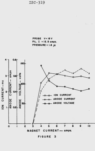
2. Magnet Current
'I'he magnet coil current was varied from 0 to 10 amperes
while probe voltage, filament current, and ion source pressu~e
were held constant. The anode voltage was adjusted to give a
~ximum ion current for each value of magnet current. As
illus-trated in Figure
-
3
a min~mum magnet current of 3 amperes wasrequir~d to maintain stable operation. The ion current
in-crea-s-ed to a _maximum at aDout,;
?
amperes which corresponds i(oa field intensity at the end of the anode of about 175 oersteds.
This perhaps indicates -that for magnet current of 5 amperes or
larger all the primary electrons from the filament are passing
through the anode. For magnet currents larger than
5
amp~s theion current actually appeared to decrease slightly.
3.
Anode VoltageThe probe voltage, magnet curren~ filament current, and the ion source pressure were held constant while the total ion
cur-rent, the anode current .. , and the ,probe current were measured for
various anode voltages. For the particular pressures used, the
ion current had a definite maximum at an anode voltage of 110
volts as illustrated in Figure
4.
At lower anode volta~es the ton current was approximately proportional to it except at very low v9ltages where the discharge became unstable. At voltagesabove 110 volts the current to the probe increased rapidly and
the ion current decreased. This perhaps can be explained ey the
hypothesis that as the anode voltage is increased the ions
be-.come more strongly focused toward the exit hole, hence, are very
diverging as they approach the probe and, consequently, strike it. Thus, although more ions are focused to the exit hole and
more are extracted, fewer are accelerated past the probe. The
current to the probe was not all ion current but in part due to
secondary electrons from the probe.
The curves of Figure
4
were displaced considerably bychanging either the spacing between the anode extension and the
bottom plate or by changing the position of the filament relative
4 Ql PROlE V. • II KY.
1!0 F'IL. CURRENT.• 12.5a.
MAG. l • Ia .
..
•
!:3 Q. 0
e
> Gd I
~e ... z LLI (!)
I
LLI~
tE
I 0: 0: ..J UNSTABLE1&1 . ;:::) 0
0: u > DISCHARGE 0:
LLI REGION
;:::) LLI
u 0 0 ~ ION CURRENT
0 0
z ~QI z ~.-ANODE CURRENT
2
c... ANODE VOLTAGE
0 0.5 1.0 1.5 2.0 2.5
ION SOURCE PRESSURE- 11>. of Ho.
12
4 0.8
..
Q.E
5 a a I
E
....
I z
....
I&Ja::
z a:: I&J 2 ::I a:: u a:: ::I I&J u 0
0
z ~
Q2
0
0
I&J 0 0 z
C(
ISC-319
PROBE V• IS V FIL. I • 12.5 a111p1.
PRESSURE • 1.1 jJ.
~ ION CURRENT
_.__._ ANODE CURRENT ...,._ ANODE VOLTAGE
2 5 4 5 e 1 1 MAGNET CURRENT-ampa.
FIGURE 3
I 10
[image:15.593.152.455.69.551.2].
-14
ISC-319some conditions.
4.
Filament currentEarlier tests on the ion source had indicated an une*Pe6ted
dependence of the ion output on the filament emission. Figure
5 illustrates this dependence as a function of filament current
for constant probe voltage, magnet current, and ion source ·
pressure. Again the anode voltage was adjusted to give a
maxi-mum ion current for each filament current. The ion output
in-creased with filament current to a maximum at 12.5 amperes and
then decreased for larger filament current. Perhaps this
de-crease in ion current is due 'to' neutralization of the ions by
the electronic space <ffiat~ge :aboul;i -lthe'rfli.lament.
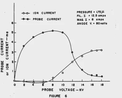
5o Probe Voltage
For a constant ion source pressures filament current, magnet
current, and anode voltage the ion current was measured as the
probe voltage was variedo The results are illustrated in
Figure 6. At very low voltages nearly all the ions were striking
the probe, and hences there was very little ion current. The
ion current actually read negative due to secondary electrons from
the probeo As the probe voltage was increased the ion current
increased to saturation at about 16 kv. It is difficult to draw
any conclusions from these data since the number of secondary
electrons coming off of the probe and the number collected with the
ion current were unknown. In generals after the saturation point
for the ion current is reache~ an additional increase in ion
current could be achieved by increasing the anode voltage.
Additional tests were made by applying the high voltage
(10 to 300 kv) to the accelerating tube.
6. Foe us~ing
The focusing was adjusted by varying the voltage on the
first electrode of the accelerator tube (0 to 10 kv with respect
to the ion source case). The focusing conditions and the degree
of focusing which could be obtained were found to be very
de-pendent on both the beam intensity and the accelerating voltage.
The best focus obtained for a 3 rna beam at 300 kv on a target
about 2 meters from the ion source was a beam diameter of about
5 mm. This could probably be improved by making the exit hole
smaller. As the accelerating voltage was decreased below 150 kvs
it was necessary to decrease the beam intensity in order to
main-tain good foc~sing. Presumably this was due to space charge
effects in the beam. In the region below 20 kv it was difficult
to focus beams larger than
t
rna to a diameter of less than3
em4 PROBE V• 16 Kv MAG. 'I. 6 amp•
PRESSURE • 1.70 p.:
•
.,
-Q.
--3e
0 >0
I
0
I
e
I .,_I z ~ ION CURRENT .,_ LIJ -X-J&- ANODE CURMNT
... --x
z a:: ..,.._ANODE VOLTAGE
~2 a:: ::J )t ... x
x"
0::· 0
/
::J
,,
u
UNSTABLE X"
"
z DISCHARGE /
~I R£GIGN
0._~"---~IA~---~L---O . 9 10 II 12 13 14 15
16
0
e
t-1
z.,_
l&lz
0:1&1
O:g:
:;)a: U::;,
u
1&1
-~
z
g:O G.
,_;
~
0
0
ISC-319
~ ION CURRENT
~ PROBE CURRENT
PRESSURE • L75fl. FIL. X • 12.5 ampa
MAG. ~ • 6 amp• ANODE V. • 80volta
10 12 14
[image:19.587.94.489.188.504.2]VOLTAGE-~-V
7. Proton Percentage
The ion beam composition was studied with a magnetic analyzer. The proton percentage was measured for several ion source conditions and was found to vary over the range of
5 to 10%. The ion source conditions for a particular measure~
ment were·as follows:
Filament current Magnet current
Ion source pressure Probe voltage
Probe current .
First electrode voltage Anode voltage
Anode current
Total beam current
12.5 6.0 1.9 7.0 2.5 4.0 70. 0.42 300 amperes amperes microns kv rna kv volts amperes ua
The components of the ion beam were identified as followsg
Component
Protons H+ +
Diatomic ions H2 Triatomic ions H3~
Misc. heavy ions
Collector Current-ua
1.7 13.9 4.5 0.4
% of Total Current
8.3% 67.8% 21.9%
The remainder of the ion current was lost
td
the slits o~.the magnetic analyzer. Although. the above ion source conditions were considerably different from chose required to produce total beam currents of 2 to 3 rna, the results of the analysis ~e typical for the pressure and magnet current used.8.
Gas ConsumptionA palladium leak was used to admit the hydrogen gas into
the ion source. When the ion source was not operating but a pressure of 1.75 microns was maintained in it the gas flow was measured to be 20.5 ~ 3.4 cc/hr, STP. The gas consumption when the ion source was operating at a pressure of 1.75 microns and with a 2.5 rna beam was measured to be 22.5
±
2.8 cc/hr, STP. A 2.5 rna beam of diatomic ions was calculated to be equivalent to a gas flow of 2.09 cc/hr, STP. Kistemaker and Dekker defined a gas economy figure as the number of ions extracted from theso~rce per neutral gas molecule escaping through the exit hole. Accordingly, our figure would be 10.2% compared with Kistemaker and Dekker's value of 50%. Our low gas economy figure was in
2art due to the large exit hole used during these measurements.
In earlier tests the exit hole was 0.06 in. in diameter but was enlarged to 0.12 in. in diameter in an effort to increase the ion output. However, this change did not significantly increase
18 ISC-319
higher pressure than that reported by Kistemaker and Dekker.
9. Power Consumption
Anode 50 watts
Anode ballast 50 watts
Filament 25 watts
Magnet 60 watts
Pd leak 9 watts
Probe 16 watts
First electrode 10 watts
Total 221 watts
Misc. power to power
supplies and blowers 250 watts
The top plate and magnet of the ion source were cooled
with a blower. No difficulty with overheating was encountered.
V. SUMMARY AND DISCUSSION
The performance of the Kistemaker and Dekker type ion
source described above has been stable and reliable while
operating at pressures of 1.5 to 2.5 microns and producing ion currents of 3 ma. Its gas consumption is relatively high
(22.5 cc/hr, STP) but could be reduced by using a smaller exit hole. The proton percentage is extremely low (the order of
8%),
but this could possibly be improved some by coating the metal
surfaces which are exposed to ·:Qhe discharge with a suitable
material to reduce the recombination of the H atoms. The best focusing gave a beam diameter of 5 mm on a target 2 meters from
the ion source. It is felt that the focusing could be improved
by redesigning the shape of probe and by decreasing the size of the exit hole. The filaments have had lifetimes of from 50 to
more than 100 hours which has been satisfactory for our work
considering the ease with which the filament can be replaced.
By varying the anode and filament dimensions and increasing the
power to the discharge, ion currents as large as 5 rna were
ob-tained, and perhaps by further adjustment of these parameters
even larger ion currents could be obtained. This ~ould
pro-bably shorten the lifetime of the filament considerably. The
power consumption for beams of 3 rna or less was found to be
about 0.15 watts/ua.
The chief disadvantage of this ion source for out 'work
'is its low proton percentage. It is felt that considerable
effort would be required to increase the proton ratio
signi-ficantly and its upper limit would be of the order of 50%.
Recent reports on the development of R.F. ion sources (7,8,13,
14) have led us to the opinion that future work can be more
profitably applied to the construction of~ R.F. type ion
source. Consequently, the design and plans for construction
VI. LITERATURE CITED
1. W. N. Zinn, Phys.
Rev., 52,
655 _(1937).2. James 0. Gow, Private communication from University of California, Berkeley, California, 1949.
3. Carl Bailey, D. L. Drukey, and F. Oppenheimer, RS~ 20,
189 (1949).
-4. J. Kistemaker, H. L. Douwes Dekker, Physica, 16, 198 and 209 (1950).
5. R.C. Cornelius and G. W. Farwell, AEC Report, LA-1260, 1951.
6. Robert N. Hall, RS~ 19, 905 (1948).
7. P. C. Thonemann, J. Moffatt, 0. Roaf, and J. H. Sanders, Proq. Phys. Soc. (London), 61, 483 (1948).
8. C. D. Moak, H. Reese, Jr., and W. M. Good, Nucleonics,
9,
Sept., p. 18, (1951).
9. Akira Isoya, J. of Phys. Soc. of Japan, 7, 275 (1952) .
10. P. C. Veenstra and J. M. W. Milatz, Physica, 16, 528 (1950).
11. P. C. Veenstra and J. M. W. Milatz, Helv. Phys. Acta, 23, Suppl. III, 39 (1950).
12. Paul Lorrain, Can. J. Res., 25A, 338 (1947).
13. J. R. Pierce, J. of Appl~ed Phys.,