Ames Laboratory ISC Technical Reports Ames Laboratory
7-20-1950
Micro-pipette remote control
J. Weber Jr.
Iowa State College
E. Dewell
Iowa State College
Follow this and additional works at:http://lib.dr.iastate.edu/ameslab_iscreports Part of theChemistry Commons, and theEngineering Commons
This Report is brought to you for free and open access by the Ames Laboratory at Iowa State University Digital Repository. It has been accepted for inclusion in Ames Laboratory ISC Technical Reports by an authorized administrator of Iowa State University Digital Repository. For more information, please [email protected].
Recommended Citation
Micro-pipette remote control
Abstract
A micro-pipette remote control mechanism was developed to satisfy the need for handling small quantities of extremely radioactive materials. The sampling had to be done with the complete protection of the operator by means of proper shielding. Quantities as small as 5 lambda were handled and had to be delivered with the assurance that accuracy of measurement was maintained. Ease of operation was also an element considered in the production of this mechanism.
Disciplines
Chemistry | Engineering
ISC-112
MICRO-PIPETTE REMOTE CONTROL
By
J. Weber, Jr. E. Dewell
July 20, 1950
Iowa State College
Reproduced direct from copy as submitted to this office.
Work performed under Contract No. W-7405 eng 82
PRINTED IN USA PRICE 5 CENTS
MICRo-PIPET'l'E REMarE CONTROL
J. Weber, Jr. and E. Dewell
General
A micro-pipette remote control mechanism was developed to satisfy
the need for handlin, small quantities of extremely radioactive materials.
The sampling had to be done wi. th the cox11plete protection of the operator
by means of proper shielding. Quantities as small as 5 lambda were
hand-led and had to be delivered with the assurance that accuracy of
measure-ment was maintained. Ease of operation was also an elemeasure-ment considered
in the production of this mechanism.
The advantages permit sampling of extremely radioactive liquid
materials wi. th ease. The width of the range of pipettes used is almost
unlimited and would depend entirely upon the number of heads constructed.
Further details of the pipette heads are discussed later. The pipetting
of quantities from 5 lambda to 250 lambda is typical and common practice
at the Ames laboratory.
A typical setup as used at Ames consists essentially of the remote
control panel which supports the observation telescope, the control cables
which link the panel to the pipette mechanism proper, and the necessary
shielding, the design of which is unlimited. The control panel is self
explanatory, while the pipette mechanism consists of a base and tube
which support a gear assembly, which controls the pipette proper. This
assambly provides a means of raising and lowering the pip~tte and also
a means for drawing the liquid sample up into the pipette to ~he
re-quired graduation mark. The table may be revolved to any desired
ISC-112 2
position through a gear arrangement in the base. The proper mechanical
advantage has been incorporated such that ease of operation and accuracy
is maintained at all times.
It might be mentioned that the uses for this instrument may be
ex-tended beyond that for which it was originally designed. In beta-ray
spectrometer work, radioactive samples are often evaporated to dryness
drop by drop upon the surface of a very thin mica membrane. A stop
attachment limiting the downward motion of the pipette could very easily
be constructed as an integral part. This could previously be set such
that the lower tip of the pipette would come within the desired distance
from the mica membrane, in order to deposit the drop with ease and the
assurance that the membrane would not be punctured. The sample could
then be rotated from beneath the pipette and placed under a heat lamp,
or if fumes are objectionable, under a small hood and heater unit.
Discussion
In the construction, stainless steel was used for practically all
parts, because of its resistance to the usual corrosive atmosphere of
the chemical laboratories. Where a high polish could be maintained, the
ease of decontamination would be facilitated. The time consumed in the
manufacture of this mechanism was about 125 hours. The cost of materials
and standard remote cables was $75.00. It shruld be pointed out that a
perfectly satisfactory product could have been had by using iron and
bronze in the fabrication. A light chromium plate would have provided
ISC-112 3
as the use of snall rods and universal joints to replace the expensive
control catles, could have substantially reduced the over-all cost.
Three cables with male ends, of the type used for remote control of
radios, were employed. The cables were coupled to three large radio
knobs located on the control panel.
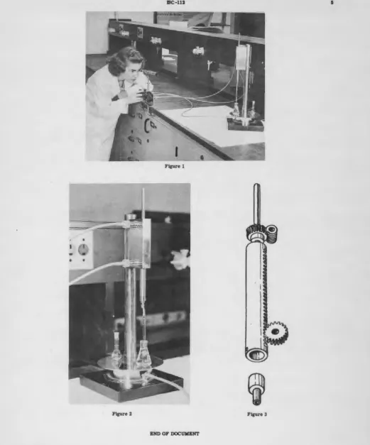
It may be seen from Figure 1 that the operator has the advantage
of observing the pipette meniscus through the telescope mounted above
the control panel. This telescope is of the type used in reflecting
galvanometers. The image, of course, is inverted in this case. However,
this minor disadvantage may be overcome to a degree by using a large 90°
prism placed immediately in front of the telescope with the plane of the
hypotenuse parallel to the ground plane and line of sight. This will give
an erected ixn:l.ge vertically; however, from left to right the inage will
be reversed.
Photographs of the instrument and its operation are shown in Figures
l and 2. Shielding has not been shown in this case for the sake of
sim-plicity. If the sample is so active that even a telescope port in the
shielding is prohibited, a double mirror arrangement will permit an
off-set of the line of sight of the telescope.
Figure 3 is a drawing showing the heart of the pipette mechanism.
The small rack of the quill and its engaging pinion cause the pipette to
be raised and lowered. The worm gearing at the top gives complete control
of the head which is shown at the bottom with the short rubber tube for
connection to the pipette. Figure 3 also shows haw the various heads
may
ISC-112 4
The wide range of pipettes used is obtained by the use of inter-changeable heads. These heads are simple to construct and very easily
removed for replacement by one set screw. If machined properly, a very
small amount of silicon grease will provide sufficient seal, which is
quite desirable in order to promote a positive actionwithin the pipette.
Operation
Prior to the use of the instrument a pipette of the volume desired
(up to 250 lambda with the present head) is attached with a short rubber
connector. The hot sample is then placed an the table along ~th the
receiving container and a rinse bath. Alignment of the vessel with the
pipette is aided by centering marks cut into the rotating table at four
different positions.
The hot sample is centered beneath the pipette by means of the table
control and the pipette is lowered into the solution by means of the
height control. After adjusting the meniscus level with the help of
the telescope, the pipette is raised. The clinging drop on the pipette
is touched off by coordinating the table control with the height control
as the pipette is withdrawn. The receiver is then rotated into position
and the pipette discharged into it. Since most micro-pipettes are
calibrated to contain a given volume, the pipette must be rinsed into
the receiver several times. This is done by revolving the rinse bath
ISC-112 5
Figure 1
Figure 2 Figure 3