International Journal of Innovative Technology and Exploring Engineering (IJITEE) ISSN: 2278-3075, Volume-8 Issue-9, July, 2019
Design and Analysis of Textile Antenna using EBG
Structure
M. Ramesh, V. Rajya Lakshmi, P. Mallikarjuna Rao. Abstract- In this article, the rectangular textile antenna is
embedded with E-shape Electromagnetic Band Gap (EBG) Structure for reduction of SAR. It is positioned on human phantom model. The E-shape EBG array is positioned between ground and patch of rectangular textile antenna. It is resonant at 2. 4GHz.The substrate material for the rectangular Textile antenna is jeans cloth. The Specific Absorption Rate (SAR), Reflection coefficient and Impedance Bandwidth are obtained with and without EBG structure using HFSS software and also measured.
Index: -Textile Antenna, EBG, SAR.
I. INTRODUCTION
In the modern era, the demand for wireless communication around human body is increased due to the availability of miniaturization of electronic devices. Body Centric Communication is used for different applications like telemedicine, battleground, tracking of person and for players to monitor their health conditions. For Body Centric Communication, Textile antennas are used. It supports on body and off body communications [1]. For microstrip antenna, ground, patch is made with conductive materials such as copper and substrate is made with dielectric materials such as FR4, RT/Duroid. But textile antennas are made with conductive and non-conductive fabrics. The conductive clothes are used for ground, patch like ShieldIt, Flectron. Non-conductive clothes like jeans, felt and Dacron are used for substrate [2]. Textile antennas are used for WBAN applications because Textile materials are comfortable and flexible to wear on human body when compared with conventional microstrip antennas. For wearable applications, the wearable antennas are used very close to human body. The wearable antenna radiates EM waves, when close to the human body and the tissues of human body are more affected by EM waves. The SAR value must be less than 1.6 Watts/kg (over 1g of tissue) by FCC standards and less than 2 Watts/kg (over 10g of tissue) by ICNIRP [3]. Previously, SAR can be minimized using different methods which are proposed here. In [4], multiband monopole antenna was designed using FR4 substrate with square shape EBG cells, gap between the cells is 1mm and SAR value is reduced to less than 2W/kg. PIFA antenna is designed using Interdigitated and square shape via EBG cells for reduction of SAR [5]. The Authors designed PIFA antenna with strip shape Artificial Magnetic Conductor (AMC) for reduction of SAR.
Revised Manuscript Received on July 05, 2019
Ramesh M, ECE, GITAM University, Visakhapatnam, India.
Rajya Lakshmi. V, ECE, ANITS, Visakhapatnam, India.
Mallikarjuna Rao. P, ECE, Andhra University, Visakhapatnam, India.
The strips are positioned above and below the substrate [6]. The folded loop antenna is operating at 2GHz. The antenna and human body are separated by reflector and SAR is reduced to 85%. The SAR can be reduced by using RF Shields, the reduction of SAR depends on the position of RF Shields [7]. Radiation effect can be reduced by using polymeric ferrite sheets and resonant frequency is not influenced by ferrite shield but reduces the SAR value [8]. In [9], the authors proposed reconfigurable textile antenna for ISM band applications. The metamaterials are used for minimization of SAR value and bending effects, it is embedded with felt substrate. In [10], the authors proposed inverse E-shape wearable antenna combined with four strap lines and square loop EBG cells for minimization of SAR value at ISM band wearable applications. The overall antenna is implemented with jeans and ShieldIt fabric. The two by two EBG array is positioned under the antenna. In [11], the novel Z-shape EBG structure is combined with textile antenna, then the averaged SAR value is reduced to 1.26 W/kg over 10 g of tissue at 0.3 watts of input power. In [12], the authors proposed negative refractive index Metamaterials for reduction of SAR value and it is used for multiband antenna applications. In this paper, section II represents the design of textile antenna and novel E-shape EBG structure. The analysis of results and the proposed method are given in Section III. Finally, the section IV represents the conclusions. The proposed Textile antenna is used for application of wearable.
II. TEXTILE ANTENNA DESIGN
A. Analysis of Rectangular Textile Antenna
Initially, a rectangular textile antenna is designed. It consists of three different layers like ground, substrate and patch respectively.
(a) (b)
Fig.1 Schematic of rectangular Textile antenna, (a) Front view, (b) Side
The copper material is used for the patch, ground and jeans fabric for the substrate. The figure 1(a) shows the schematic front view of rectangular textile antenna and figure 1(b) shows the side view.
Initially, the parameters of Rectangular shape patch are calculated using the following equation [13]. Next, the parameters are optimized for better results
(2)
(3)
L, W are length and width of patch, - resonant frequency, -relative permittivity of substrate, c-speed of light. Let the effective relative permittivity,
(L) =
(4)
-effective permittivity of substrate, h-thickness of
substrate,
(5)
= 0.412 (6)
-effective length due to fringing fields.
The length is 70mm and width is 65mm of the ground plane. Next, the size of substrate is Ls= 70mm, Ws=65mm with
thickness of 3.3mm. The dielectric constant of jeans fabric is 1.67 with loss tangent 0.023[2]. The multiple layers of jeans cloth is used as substrate to achieve a particular height of the substrate for a proposed textile antenna. The size of the patch is L= 43mm and W= 36mm which is positioned on the substrate. The proposed feed is Microstrip line, its length and width are Lf=30mm, Wf = 2mm respectively.
B. Design of E-shape EBG structure
Fig.2. Dimensions of Proposed E-shape EBG cell.
The figure 2 shows the dimensions of E shape EBG cell. The length is Le = 20mm, width is We = 17.5mm and the
position of the rectangular EBG structure from ground plane is 2.4mm. The array size of EBG structure is 3x3.The gap between adjacent cells in horizontal direction is g=0.5mm. The E-shape EBG cell has periodicity is 18mm. Here the substrate is implemented with jeans fabric. The width of the
slots of EBG cell influence the reflection phase of E-shape EBG cell, then the width of the slots are optimized to achieve a zero phase at desired frequency.
(a) (b)
Fig.3. Fabricated (a) Rectangular textile antenna (b) E-shape structure
The front view of the fabricated rectangular textile antenna is shown in figure 3(a) and top view of the E-shape EBG structure is shown in 3(b). The E-shape EBG structure is kept between ground and patch at 2.4mm distance from the ground plane. The E-shape cells, jeans fabric and rectangular patch are manually cut with scissor and tape is used to stack them.
C. E-shape EBG array embedded Rectangular textile antenna
The Figure 4(a) shows the textile antenna is embedded with E-shape EBG structure on a phantom model of human body and side view of the antenna is shown in 4(b). The array of EBG structure is positioned at 2.4mm from the ground plane. Here, ground surface and EBG structure are separated with jeans cloth as a substrate. Next, the rectangular patch is positioned on EBG structure at a height of 0.8mm, whereas jeans fabric is placed between EBG and patch. The ground structure is positioned at 2mm from the Human body.
(a) (b)
Fig.4.Textile antenna with E-shape EBG array view (a) Front (b) Side
III. ANALYSIS OF RESULTS
All the Results are verified using Ansoft HFSS software for Textile antenna and EBG cell.
International Journal of Innovative Technology and Exploring Engineering (IJITEE) ISSN: 2278-3075, Volume-8 Issue-9, July, 2019
1.50 2.00 2.50 3.00 3.50 4.00
Frequency [GHz] -200.00
-150.00 -100.00 -50.00 0.00 50.00 100.00 150.00 200.00
R
e
fle
ctio
n
P
h
a
se
[
d
e
g
]
. ANSOFT
m2
m4 m1
Curve Info phase Set : Sw eep
Name Delta(X) Delta(Y) Slope(Y) InvSlope(Y) d( m1,m2) 0.0711 -91.9374 -1293.6173 -0.0008
Name X Y
m1 2.3419 92.0580 m2 2.4130 0.1206 m4 2.4670 -90.9979
Fig.5. Reflection Phase of E- shape EBG cell.
The graph between the reflection phase and frequency for the proposed shape EBG cell is shown in figure 5. The E-shape EBG cell is excited with incident of plane wave at normal incidence. The reflection phase varies from + 1800 to -1800 but from +90o to -90o, this interval represents reflection phase bandwidth and reflection phase is zero degrees at 2.41 GHz. The structure behaves as Electromagnetic Band Gap from 2.34GHz (+90o) to 2.46 GHz (-90o), in this interval the surface waves are suppressed, it is a unique feature of EBG structure.
B. Reflection coefficient
Fi g.6.Rectangular textile antenna w/o Phantom Model and EBG
The figure 6 shows the simulated reflection coefficient is -14.17dB at 2.4GHz of rectangular textile antenna without EBG structure, without Phantom model and impedance bandwidth (< -10 dB) is 170MHz. Here, as
lower cutoff frequency, as upper cutoff
frequency.
Fig.7 Measured Reflection coefficient of rectangular textile antenna without EBG
The figure 7 shows the measured reflection coefficient is -13.03dB at 2.46 GHz of the rectangular textile antenna without EBG, without human body.
Fig.8. Textile Antenna with phantom model and without EBG.
The figure 8 shows Reflection coefficient of the rectangular textile antenna with Phantom model, without EBG structure. The antenna is resonant at 2.5 GHz with Reflection coefficient of -8.67dB. The Reflection coefficient of the rectangular textile antenna is affected due to the Human body since it is a lossy medium. This effect can be reduced using E-shape EBG structure.
1.00 2.00 3.00 4.00
Frequency [GHz] -24.97
-20.00 -15.00 -10.00 -5.00 0.00
Re
fle
ct
io
n
co
e
ff
ici
e
n
t
(d
B
)
. ANSOFT
m1
m2 m3
Curve Info dB(S(1,1)) Setup1 : Sw eep
Name X Y
m1 2.4000 -24.0561 m2 2.3100 -11.1498 m3 2.6100 -10.6522
Fig.9.Reflection coefficient with E shapes EBG on human phantom model.
The Impedance bandwidth (<-10dB) is 300MHz (from 2.31GHz to 2.61 GHz). The impedance bandwidth is increased due to E-shape EBG structure.
Fig.10.Measured Reflection coefficient of rectangular textile antenna with EBG structure on human body
[image:4.595.298.546.152.369.2]The measured Reflection coefficient of rectangular textile antenna with E-shape EBG structure on human body is shown in figure 10. The measured resonant frequency is 2.43GHz with reflection coefficient -32.3dB.
Fig.11 VSWR of rectangular textile antenna by E shape EBG structure.
The VSWR of rectangular textile antenna combined with human phantom model and E-shape EBG array. The VSWR value (<2 is reference line) is 1.13 at 2.4GHz.
C. Radiation Pattern
[image:4.595.55.285.357.488.2]The figure 12 shows the radiation pattern of rectangular textile antenna embedded E-shape EBG array and it is positioned on human phantom model. The graph shows back lobe radiation is reduced.
Fig.12.Radiation Pattern of Antenna with EBG structure.
D. Calculation of SAR
The shape of the human phantom model is rectangular and it is created by Skin, Fat and Muscle [14]. The overall dimensions of the rectangular box of human phantom model is 70 x 65 x 16 mm3. The table I give the properties of human tissues
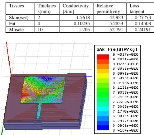
Table I: Electrical properties of human tissues at 2.4GHz
Tissues Thicknes
s(mm)
Conductivity [S/m]
Relative permittivity
Loss tangent
Skin(wet) 2 1.5618 42.923 0.27253
Fat 4 0.10235 5.2853 0.14503
Muscle 10 1.705 52.791 0.24191
Fig.13.Simulated SAR of rectangular textile antenna w/o EBG structure
Here the input power is 0.2W. The gap between the rectangular textile antenna and human phantom model is 2mm. The SAR value is calculated w/o EBG surface using human phantom model is shown in figure 13. The averaged SAR value is 9.45Watts/Kg for 10g of tissue is more than that of FCC standards (<2W/kg) and as a result of this, tissues are more effected. The surface waves are generated when the dielectric constant of substrate is more than one. The back lobe radiation is increased due to the diffraction of surface waves, and then the SAR value is increased.
Fig.14.Simulated SAR of rectangular textile antenna with E shape EBG array.
[image:4.595.310.545.520.664.2] [image:4.595.65.272.640.767.2]International Journal of Innovative Technology and Exploring Engineering (IJITEE) ISSN: 2278-3075, Volume-8 Issue-9, July, 2019
The E-shape EBG structure suppress the surface waves, then the back lobe radiation is reduced, so SAR value is minimized. The averaged SAR value is 1.36 Watts/Kg over 10 g of tissue is achieved due to E-shape EBG array. It must be less than the value specified by FCC. The E- shape EBG structure provides more isolation between textile antenna and human body.
Fig.15. Field distribution of rectangular textile antenna with E shape EBG array
The E-field distribution of proposed antenna with E-shape EBG array on human phantom model is shown in figure 15.
TABLE-II: Textile antenna with and without E shape EBG
Antenna w/o EBG and body
Antenna with body and w/o EBG
Antenna with EBG+ body
Reflection coefficient(dB)
-12.71 -8.67 -25.04
Bandwidth(MHz) 150 - 300
SAR(10g)(W/kg) - 9.45 1.36
The comparison of the rectangular textile antenna w/o and with E- shape EBG structure on human phantom model is given in Table-II. The textile antennas with E-shape EBG enhance the impedance bandwidth and reduce the SAR value.
TABLE-III: Comparison of Textile antennas
Paper fr Substrate type EBG shape EBG Cell
size(mm2)
[15] 2.4 Photo Paper Single ring 25.3 X 25.3
[16] 2.4 Rogers 3003 I 26.87 X 16
Proposed Antenna
2.4
Jeans E 20 X17.5
The proposed Textile antenna compared with other EBG structures that are given in Table –III. The proposed compact E-shape EBG cell is implemented on jeans fabric.
IV.CONCLUSION
The proposed E-shape EBG structure is integrated with rectangular textile antenna. The averaged SAR value is reduced from 9.45W/kg (without EBG) to 1.36 W/kg (with E shape EBG) for 10g of tissue. The Reflection coefficient is -8.67dB without EBG due to human body. The textile antenna with EBG is resonant at 2.4GHz with Reflection coefficient of -24.05 dB on phantom model. The 85.6% reduction in SAR value is obtained and impedance bandwidth is increased due to the E-shape EBG structure.
REFERENCES
1. Mehmet R. Yuce and Jamil.Y.khan, “wireless body area networks
technology, implementation and applications, “Pan Stanford publishing, 2011.
2. Ramesh. M, Rajyalakshmi. V and Mallikarjuna Rao. P,” Design and
Analysis of Crescent Shape Textile Antenna for WLAN Applications,” IEEE 7th International Advance Computing Conference (IACC), Jan-2017, pg.3.
3. International Commission on Non-Ionizing Radiation
Protection(ICNIRP), Guidelines for limiting exposure to time-varying electric, magnetic and electromagnetic fields (up to 300 GHz), Health Phys 74(1998), pg.494–522.
4. Kamel S. Sultan1, Haythem H. Abdullah,Esmat A. Abdallah1, and
Essam A. Hashish,” Low SAR, Compact and Multiband Antenna,” Progress in Electromagnetic Research Symposium Proceedings, Taipei, March 25, 2013 pg.748-751.
5. Kwak, S. I., D. Sim, and J. H. Kwon, Design of optimized multilayer
PIFA with the EBG structure for SAR reduction in mobile applications," IEEE Transactions on Electromagnetic Compatibility, Vol. 53, No. 2, May 2011, pg.325-333,
6. Jae-Gon Lee and Jeong-Hae Lee,” SAR Reduction Using Integration
of PIFA and AMC Structure for Pent Band Mobile Terminals,” Hindawi International Journal of Antennas and Propagation Volume 2017, Article ID 6196721, pg.7
7. Akimasa. Hirata, Takahiko Adachi, and Toshiyuki Shiozawa,”
folded-loop antenna with a reflector for mobile handset at 2.0 GHz,” Microwave and Optical Technology Letters, Vol. 40, No. 4, February 20 2004 pg.272-275.
8. T. Alves, R. Augustine, M. Grzeskowiak, B. Poussot, J.-M. Laheurte,
"Polymeric ferrite-loaded antennas for on-body
communications", Microwave and Optical Technology Letters, vol.
51, no. 11, November 2009, pp. 2530-2533
9. Sen Yan and Guy A. E. Vandenbosch,” Radiation
Pattern-Reconfigurable Wearable Antenna Based on Metamaterials Structure,” IEEE Antennas and Wireless Propagation Letters, Vol. 15, pg.1715-1718, 2016.
10. Adel Y. I. Ashyap, Zuhairiah Zainal Abidin,Samsul Haimi
Dahlan,Huda A. Majid,Shaharil Mohd Shah, Muhammad Ramlee
Kamarudin,and Akram. Alomainy,” Compact and Low-Profile
Textile EBG-Based Antenna for Wearable Medical Applications,” IEEE Antennas and Wireless Propagation Letters, Vol. 16, 2017, pg.2550-2553.
11. M. Ramesh, V. Rajya Lakshmi and P. Mallikarjuna Rao,” Textile
Antenna with Z shape EBG structure for SAR Reduction,” ARPN Journal of Engineering and Applied Sciences, Vol. 12, No. 6, pg.1860- 1863, March- 2017.
12. Alam, Touhidul, Mohammad Rashed Iqbal Faruque, and Mohammad
Tariqul Islam. "A double-negative metamaterial-inspired mobile
wireless antenna for electromagnetic absorption
reduction." Materials 8.8 (2015): 4817-4828.
13. Constantine A. Balanis, “Antenna theory Analysis and design,” John
Wiley & Sons, Inc., Hoboken, New Jersey.
14. Gabriel C. 1996. Compilation of the Dielectric Properties of Body
Tissues at RF and Microwave Frequencies. Brooks Air Force
Technical Report, AL/OE-TR-1996-0037: www.
iremf.ifac.cnr.it/tissprop/
15. Sangkil Kim, Yu-Jiun Ren, Hoseon Lee, Amin Rida, S.Nikolaou and
Manos .M Tentzeris,”Monopole Antenna with Inkjet printed EBG Array on paper substrate for Wearable Applications”, IEEE Antennas and Wireless Propagation Letters,Vol.11,2012. Pg.663-666.
16. Zhi Hao Jiang, Donovan E. Brocker, Peter E. Sieber, and Douglas H.
Werner,” A Compact, Low-Profile Meta Surface-Enabled Antenna for Wearable Medical Body-Area Network Devices,” IEEE Transactions on Antennas and Propagation, Vol. 62, NO. 8, AUG- 2014, pg.4021-4030.
Authors profile
Ramesh MANIKONDA is working as an Assistant Professor in GITAM University, Visakhapatnam. He received his M. Tech. Degree from Andhra University in 2006 and pursuing Ph.D. from Andhra University. His research interests include Microstrip Antenna,
wearable antenna and wireless communication.
Visakhapatnam. She received her M. Tech and Ph.D. Degree from Andhra University. Her research interests include Wearable Antenna, Antenna Array and Microstrip Antenna.