Abstract: An oscillating water column (OWC) extracts the power of waves by trapping air above a water column. This trapped air is compressed and decompressed by the wave action flow inside a turbine power to the mechanical power during process, and it is important as the turbines are expected to operate in oscillating and reversing flows over a wide range of conditions. The objectives of this study are to determine and analyze the type of radial impulse turbine of OWC and to optimize the performance of a radial impulse turbine for OWC by using Computational Fluid Dynamics (CFD). This requires a comprehensive investigation on turbine configuration, turbine efficiency, OWC integration, and turbine operation with respect to climate condition. The outcome of this study to settle the main drawbacks of radial turbine namely lower peak efficiency and damping on OWC can be considered. Later, these problems will be further study to identify the behavior of the airflow through the machine, sources of energy loss, and impact of different parameters on the turbine performance.
Keywords: Oscillating water column (OWC), Computational Fluid Dynamics (CFD) Analysis, Radial Impulse Turbine
I. INTRODUCTION
With the ever-increasing demand for energy in today’s world, employing the renewable energy sources such as solar, ocean and wind ensures a longer way to protect our environment. Renewable energy technologies produced power, heat or mechanical energy by converting those resources either to electricity or to motive power.
Ocean waves are significant sources of renewable energy that can be exploited using wave energy convertor plants (WEC) in order to generate electricity. A kind of WEC devices called oscillating-water-column (OWC) extracts the power of waves by trapping air above a column of water. This trapped air is compressed and decompressed by the wave action to flow inside a turbine coupled to a generator.
Until now, the most common turbine used in OWC was the Wells turbine. But [1] made a study of this turbine and found that the Wells turbine has many drawbacks, such as low efficiency far from the best efficiency point, stall when the flow rate is too high, a very high rotation velocity and the long time in reaching operational velocity. In order to avoid
Revised Manuscript Received on October 05, 2019.
K. A. M. Saad, Marine Engineering Technology, Universiti Kuala Lumpur, Marine Institute of Marine Engineering Technology, Lumut, Malaysia
Mohd Firdaus Al Musanna Bin Ahmad, Marine Engineering Technology, Universiti Kuala Lumpur, Marine Institute of Marine Engineering Technology, Lumut, Malaysia
these problems, many modifications have been proposed, including guide vanes, variable-pitch angle blades, several rotors, contra-rotating rotors, using different chord blades and geometry ratios. One of the alternatives to the Wells turbine is the impulse turbine: axial or radial.
Impulse turbine has few types of design which is impulse turbine with self-pitch-controlled guide vanes, impulse turbine with active-pitch-controlled guide vanes, impulse turbine with fixed guide vanes, and McCormick counter rotating turbine. Each design has their features and operational method that contribute into same function of turbine for OWC.
II. LITERATURE REVIEW
This study presents a comprehensive review of OWC technologies and air turbines [2]. This is followed by a survey of theoretical, numerical and experimental modelling techniques of OWC converters. Its explain operation of OWC, location and principle for each type. Energy provides a convenient and natural concentration of wind energy in the water near the free surface. The waves can travel thousands of kilometers with low energy lost. Waves impinging on the device cause the water column inside the chamber to oscillate, which gives its name to the system. The water column act as a piston, forcing the air in the upper part of the chamber to flow alternatives out of the chamber and into it, driving the turbine in the process.
Study about Concept of Radial Impulse Turbine for Oscillating Water Column (OWC) [3]. Radial impulse turbine has three types which is radial impulse turbine fixed guide vanes, radial turbine with active-pitch controlled guide vanes and McCormick counter rotating turbine. Fixed guide vane of radial impulse turbine which consists of a single stage type having one row of rotor blades attached to a vertical shaft and two rows of fixed stator blades. Active pitch-controlled guide vanes are rotated and controlled by the stepping motors, timing pulleys and timing belts. The McCormick counter rotating runners and guide vanes located both upstream and downstream and the alternating airflow in the energy converter excites the turbine runners after being turned by the guide vanes.
Study about Structural Dimensional of radial impulse turbine Oscillating Water Column [4], [5]. The important for structural dimensional to get the steady efficiency was inner guide vanes, rotor and outer guide vanes. The IGV guide the
Optimization of Radial Impulse Turbine for
Oscillating Water Column Wave Renewable
Energy
flow towards the rotor adequately during the exhalation. Study about Environmental impact [2]. Radial impulse do not have any moving parts underwater, meaning no organisms will get caught inside of a turbine. Several issues that have been discussed regard the visual aspect of having a radial impulse for OWC onshore or right offshore, it would destroy the view and would generate noise pollution. However, if located in deep sea, it would be far enough offshore so it could not be seen or heard. The OWC itself will operate as an artificial reef to increase the marine species in an area.
III. METHODOLOGY
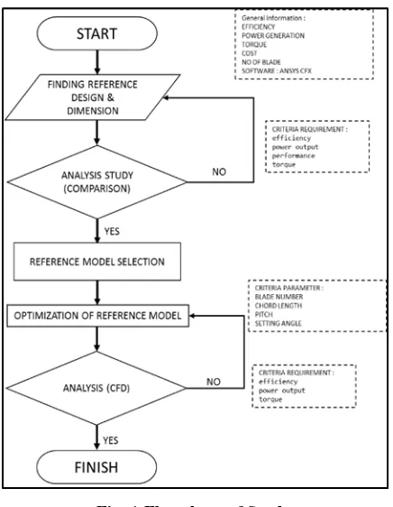
[image:2.595.310.544.53.535.2]Methodology cover the details explanation of methodology that is being used to make this research will complete and working well. It includes of research technique or research tools used in this research process. Most methodology of findings from this project mainly created into journal for others to take advantages and to improve the upcoming studies. The method is used to achieve an objective of the research that will accomplish a perfect result.
Fig. 1 Flowchart of Study
IV. DATA COLLECTION
In order to continue the research, turbine design was choosing based on the existing model that is currently under research. All the information of the model and their data characteristic is gain from article of conception of radial impulse turbine for an OWC and prospect wave energy in Malaysia.
Table. 1 Characteristic of Data
Table. 2 Wave Data
No FREQUENCY
(rad/s)
wavelength (m)
velocity (m/s)
1 0.1 1379.72 241.1
2 0.3 428.23 209.02
3 0.465 244.52 163.72
4 0.5 219.81 152.97
5 0.52 205.81 146.16
6 0.62 154.89 116.79
7 0.67 135.11 103.47
8 0.75 108.9 84.47
9 0.79 96.51 75.11
10 0.87 81.36 63.45
11 0.93 71.25 55.6
12 1 61.63 48.1
13 1.035 57.54 44.91
14 1.055 55.38 43.23
15 1.068 54.05 42.19
16 1.085 52.36 40.87
17 1.125 48.7 38.01
18 1.24 40.09 31.01
19 1.375 32.61 25.45
20 1.5 27.39 21.38
V. MODEL DETAIL DESIGN
The following details design need to consider are made in the implementation of the analysis or research.
Assumptions:
1. The flow dynamics are assumed to not vary with time and follow the assumption of steady state.
2. The flow is considering in viscid 3. Absolute nozzle exit flow. 4. Relative rotor exits flow angle
5. Angles between the relative flow and absolute velocity at inlet and outlet of the rotor.
6. The rotor blade has no tip gap and connects directly to the shroud of the turbine casing.
7. The following flow and turbine properties are constant: i. Density
[image:2.595.61.279.317.598.2]iii. Rotor RPM
[image:3.595.311.547.63.410.2]iv. Rotor and stator dimension
Table. 3 Turbine Geometric Parameter
VI. SIMULATION PARAMETER
[image:3.595.61.279.94.242.2]The common fixed parameters for the CFD simulations is described in this section. The generic components of the fluid, boundary conditions, numerical schemes and initial solution is described below.
Table. 4 Fluid Properties
[image:3.595.55.285.335.398.2]Many turbulence model are available the simulation found best convergence and stability with the use of the Spalart Allmaras, k-epsilon and Yeung-shih turbulence model. A table of the characteristic numbers related to the Reynolds number is shown in Table 5.
Table. 5 Characteristic Numbers
VII. MESH PROPERTIES
The structural 3dimension mesh was made on all blade rows. Some components were included to improve the exactness of the result. The blade profile based on the dimension used by Thakker, so the analysis result will be compared. Table 6 shows the mesh parameters used.
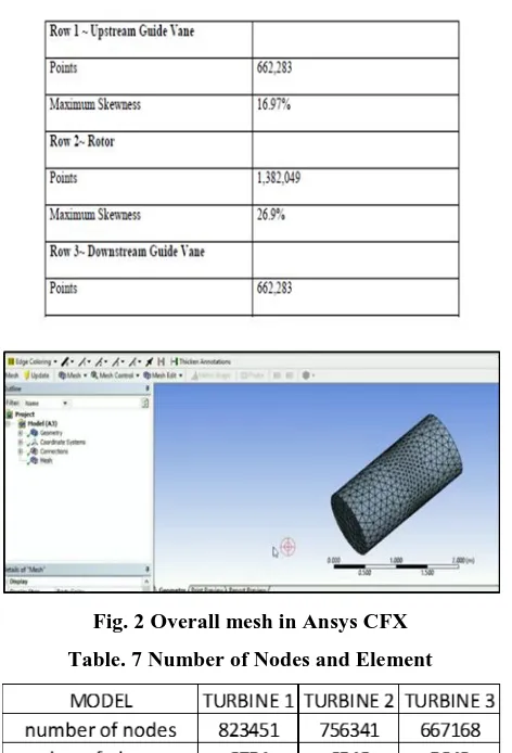
Table. 6 Mesh Parameters and Skewness
Fig. 2 Overall mesh in Ansys CFX Table. 7 Number of Nodes and Element
The most difficult parts to mesh are the leading and trailing edge of the blade. This is because the blade coming to a finite point. To resolve this problem a curve will be rounded at each leading and trailing edge blade. The rounded edge can be meshed to wrap around the edge with even distribution of nodes.
VIII. RESULT AND DISCUSSION
This discussion obtains from Ansys CFX that focuses on efficiency and power performance for turbine. Furthermore, the selection model from comparison (model turbine 1 and 2) study also through optimization (turbine 3) process to get better result and achieve objective research. All the result generated were presented in tabular form and graphically for discussion purposed based on efficiency and power performance.
IX. TORQUE
[image:3.595.49.288.493.619.2]Fig. 3 Flow Coefficient vs Torque
The result shows model 1.6 Φ at flow coefficient 0.127323 has high value of torque between other models. Maximum torque is 0.809982 nm. From the graph, the result shows minimum value of torque was 0.120709 nm at model 0.6Φ with flow coefficient 0.09549.
X. CHANGE IN PRESSURE
[image:4.595.316.546.252.411.2]In this section, the result shown comparison between changes in pressure between flow coefficients with 3 types of model with different blade diameter of turbine.
Fig. 4 Coefficient vs Change in Pressure
From the graph above, the maximum change in pressure of model 1.6Φ is the higher at 0.271 flow coefficient with the value 20.1978 pa. The minimum value of change in pressure was 0.80713 pa at turbine 1.6Φ. The graph also shown when the flow coefficient increased the change in pressure also increased because energy input in turbine.
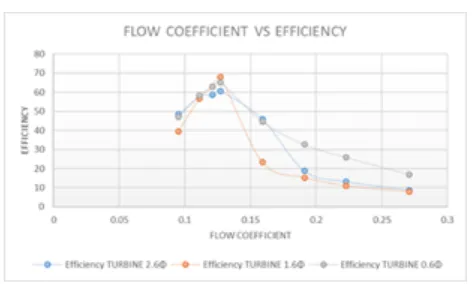
XI. EFFICIENCY
Fig. 5 Flow Coefficient vs Efficiency
There is comparison between three (3) models with different diameter of turbine. The maximum efficiency value was 67.904 at flow coefficient 0.127. The minimum of efficiency value was 7.758 at flow coefficient 0.271. The result shown the efficiency was increase started at flow coefficient 0.095 until 0.121 and the efficiency was drop after that. This is because of the certain factor which is blade number losses, whirlpool losses, end losses and the airfoil losses (Catin,Yurdusev and Ata) these loses prevent kinetic energy from being converted into mechanical energy.
XII. POWER OUTPUT PERFORMANCE
This section shown the result for the power output of turbine based on efficiency. The power output was using formula which is power input times by efficiency.
[image:4.595.49.289.334.500.2]Power output = efficiency x power input (1)
Fig. 6 Efficiency vs Power Output Turbine 1 From the graph the result shown that the highest power output was 969.264 kw/min at efficiency 60.579. While the minimum of power output was 141.04 kw/min at 8.815 efficiency.
Fig. 7 Power Output for Turbine 2
[image:4.595.310.546.483.632.2] [image:4.595.52.288.612.754.2]Fig. 8 Efficiency vs Power Output for Turbine 3 For the model Turbine 3 (0.6Φ), the maximum value for the power output was 1042.976 at efficiency 65.186 and the minimum power output is 270.368 kw/min at efficiency 16.988.
Based on the result shown, when the efficiency increased, the power output also will have increased and after the efficiency at peak or maximum value it will start to decrease because of losses at blade area.
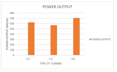
Fig. 9 Comparison of Power Output
Based on the result from the graph the power output of model turbine 3 (0.6Φ) has highest value for power output was 706.332 kW/min and suitable for Malaysian ocean.
XIII. CONCLUSION AND RECOMMENDATION
For the conclusion, the result from this research using CFD simulation ansys CFX are in good agreement with the result. Through the analysis of the result several conclusions can be made regarding the turbine parameters which have substantial effect on performance. A design of radial impulse turbine able to generate energy from Malaysian ocean wave effectively was establish with turbine 3 with the dimeter 0.6 m with average turbine efficiency of 40% to 60% throughout flow coefficient using CFD Ansys CFX. Turbine 3 have a high efficiency compare to other turbine. Profile the blade for turbine 3 which is blade number, chord length and pitch of blade have better parameter compare other blade. Based on the result, the turbine 3 has highest power output. Optimization turbine (turbine 3) can increased the efficiency and output power performance up to 20 percent.
There are some recommendations that can be the future research about the improvement of this topic. The structure of turbine need to simulate and analyze more details. Wave
experiment can compare with wave frequency of reference model. The material of the turbine blade can be analyzing in the experiment to get better result. Other software should be carried out to compare result with Ansys.
REFERENCES
1. Setoguchi T. and Takao M. (2006). Current Status of Self Rectifying Air
Turbines for Wave Energy Conversion. Energy Conversion and Management, 46, pp. 2382-2396.
2. Falcão AFDO and Henriques JCC (2016) Oscillating-watercolumn
wave energy converters and air turbines: A review. Renewable Energy 85: 1391–1424.
3. Thakker, F. Hourigan, T.S. Dhanasekaran, T. Setoguchi and M. Takao.
Computational Fluid Dynamics Benchmark of an Impulse Turbine with Fixed Guide Vanes. Journal of Thermal Science. Vol. 12, No.2. 2004
4. Pereiras, B., Castro, F., Marjani, A. and Rodriguez, M. A., 2011, “An
improved radial impulse turbine for OWC”, Journal of Renewable Energy 36 (5): 1477-1484.
5. Pereiras, B., Castro, F. and Rodriguez, M. A., 2009, “Tip clearance effect on the flow pattern of a radial impulse turbine for wave energy conversion”, Proc. International Offshore and Polar Engineering Conference (ISOPE2009), Jun 21-26, Osaka, Japan.
6. Setoguchi, T.; Santhakumar, S.; Takao, M.; Kaneko, K. (2002) A
performance study of a radial impulse turbine for wave energy conversion. Journal of Power and Energy, Vol. 216 (A1), pp. 15-22.
7. Carlos Alberto Velez (2011). CFD Analysis Of A Uni-directional
Impulse Turbine For Wave Energy Conversion
8. Badhurshah, R. and Samad, A., 2012, “Bi-directional flow turbines for
wave energy extraction”, Proc. National Conference on Fluid Mechanics and Fluid Power (FMFP2012), Dec 13-15, Gujarat, India.
9. Santhakumar, S., Jayashankar, V., Atmanand, M. A., Pathak, A. G.
Ravindran, M., Setoguchi, T., Takao, M. and Kaneko, K., 1998, “Performance of an impulse turbine based wave energy plant”, Proc. International Offshore and Polar Engineering Conference (ISOPE1998), May 24-29, Montreal, Canada.
AUTHORS PROFILE
Khairul Anuar Mat Saad, graduated Doctor Philosophy from University of Tasmania. Majoring in Maritime Engineering (Hydrodynamics). His specialization is on Seakeeping, Maneuvering, Shipbuilding, Renewable
Energy, Computational and Experimental Fluid
Dynamics. Has 16 years’ experience in shipbuilding, maintenance and repair.
[image:5.595.48.295.324.476.2]