Rochester Institute of Technology
RIT Scholar Works
Theses
Thesis/Dissertation Collections
1986
Macro assembler for mc68000 series
Grace Horng Chung
Follow this and additional works at:
http://scholarworks.rit.edu/theses
This Thesis is brought to you for free and open access by the Thesis/Dissertation Collections at RIT Scholar Works. It has been accepted for inclusion
in Theses by an authorized administrator of RIT Scholar Works. For more information, please contact
.
Recommended Citation
"MACRO
ASSEMBLER for MC68000 SERIES"by
Grace
Horng Chung
A Thesis Submitted to The
Faculty
of the School of Computer Science andTechnology
in Partial Fulfillment of the Requirements for
the Degree of Master of Science in Computer Science
Rochester Institute of
Technology
School of Computer Science andTechnology
?/g
/r?
Dater-/e-tfy
Professor Warren R. Carithers
AFPROVED:
Date
'/
Title of Thesis : Macro Assembler for MC68000 Series
I,
GraceHorng Chung
hereby deny
permission to the Wallace Memorial Library, ofRIT,
to reproduce mythesis in whole or in part.
Any
reproduction will not be for commericial use or profit.Date,
5VWP7
Abstract
The objective of this thesis is to use UNIX" utility Yacc
(Yet
Another
Compiler-Compiler)
as a languagedeveloping
tool to designand implement a MC68000 macro assembler. The assembler can support
four MC68000 machine languages
MC68000,
MC68008,
MC68010, andMC68020.
The MC68000 macro assembler translates source statements written in
the series of M68000 assembly language into their machine codes,
assigns storage locations to instructions and
data,
and performsauxiliary assembler actions designated
by
the programmer.This is a two-pass assembler which scans the source text twice:
first,
todevelop
a symbol table and to expand macrodefinitions;
second, to assemble the source program with reference to the symbol
table developed in pass one and generate the object code and
assembly listing.
Keyworks:
Cross-assembler,
Grammer,
LexicalAnalysis,
Macrodefinition,
Macroexpansion, Macro processor, Opcode
Table,
Parser,
Pseudoinstruction,
SymbolTable,
Syntactic analysis,Token,
Top-downdesign,
Yacc.Computing
Review Subject Codes : D.1.1 Applicative(Functional)
Programming
* UNIX
CONTENTS
1 . INTRODUCTION AND BACKGROUND 1
2. IMPLEMENTATION of THE MACRO ASSEMBLER 2
2.1 Functional Specification 2
2.2 Architectural Design 4
2.3 Interface Specification 9
2.A Module Designs 11
2.5 Data Bases 20
2.6 Communications among Modules 25
3. VERIFICATION AND VALIDATION 26
3.1 Test Plan 26
3.2 Test Procedures 26
3.3 Test Results 29
4. CONCLUSIONS 30
4.1 Problems Encountered and Solved 30
4.2 Discrepancies and Shortcomings of the
System 30
4.3 Lessons Learned 31
Appendix A. Extension Word Requirement 33
Appendix B. EXAMPLE OUTPUT LISTING 34
Appendix C. USER MANUAL 37
C. 1 SOURCE PROGRAM CODING 37
C.1 . 1 Comments. 37
C.1.2 Executable Instruction Format. 37
C.2 EXPRESSIONS 38
C.3 SYMBOLS 38
C.4 NUMBERS 39
C. 5 REGISTERS 39
C.6 VARIATIONS OF INSTRUCTION TYPE 39
C.7 ADDRESSING MODES 39
C.8 ASSEMBLER OUTPUT 40
C.9 ASSEMBLER DIRECTIVES 40
C.10 DEFINING A MACRO 41
C. 11 CALLING A MACRO 41
C.12 INVOKING THE CROSS ASSEMBLER 41
1 . INTRODUCTION AND BACKGROUND
Motorola
introduced
the first implementation of the MC68000 with a16-bit data bus and 24-bit address bus in 1979. It was only the
first in a
family
of processors which implement a comprehensive,extensible computer architecture. It was soon followed
by
theMC68008,
with an 8-bit data bus and 20-bit addressbus,
andby
theMC68010,
which introduced the virtual machine aspects of the M68000architecture.
Later,
in1984,
a full 32-bit implementation of theM68000
Family
of microprocessors,MC68020,
was introduced. TheMC68020 is
object-code compatible with the earlier members of the
M68000
family
but has new addressing modes in support of high-levellanguages .
The paper which follows presents a project undertaken for the
thesis requirement in the Masters Degree program in Computer
Science at the Rochester Institute of
Technology
inRochester,
NewYork. The project involved the design and implementation of a
cross- assembler which translates source statements written in the
series of M68000 assembly language into their machine codes,
assigns storage locations to instructions and
data,
and performsauxiliary assembler actions designated
by
the programmer. Thebasic aims of the assembler are:
1. To provide the programmer with the means to translate source
statements into object code which is required
by
M68000machine.
2. To provide a printed
listing
containing the source language- 2
-are useful to the programmer.
The cross-assembler makes two passes over the source code. The
first pass is responsible for
developing
a symboltable,
anddefining
and expanding macros. The second pass is to assemble theobject program with reference to the symbol table developed in pass
one.
During
passtwo,
the object code and the assemblylisting
will be generated. Each source language line will be processed
before the next line will be read.
The use of yacc
(Yet
Another Compiler-Compiler) made the syntacticanalysis for M68000 very easy when
developing
the assembler andwill be discussed more in the later chapters.
2. IMPLEMENTATION of THE MACRO ASSEMBLER.
2.1 Functional Specification.
Mnemonic operation code
The operation code may be represented symbolically. For example,
the mnemonics ADD and MOVE are more
likely
to be used forinstructions which add and move data than are the bit
configurations which represent those operations.
Symbolic Address
A programmer may select a symbol to refer to the location for an
item which is needed when the program is executed. In this
cross-assembly system, the programmer may write
- 3
and leave it up to the assembler to decide where the instruction
HOLD is to be placed. Somewhere else in his program he would have
a data item named THREE.
Storage Reservation
Some
data-defining
pseudo-instructions are provided for storagereservation and constant definition. A storage specification may
optionally be preceded
by
a label. The label references the lowestaddress of the defined storage area.
Symbol Table
The symbol table keeps the coalescence of data relating to the
various elements of the source text and provides the data for
describing
certain relationships between the text and the M68000machine.
Code Generation
For each instruction in pass two, the assembler creates the
equivalent machine language instruction accepted
by
the M68000machine.
Location Counter
M68000 instructions are of variable
length,
so the increment of thelocation counter is based upon data item size, such as
byte,
wordand
long
word and the addressing mode of the operand. A singlelocation counter is implemented.
User-Defined Macro
By
using a macroinstruction,
the M68000 user is spared the tedium- 4
-to the programmer because he has defined them along with their
formal parameters.
Pseudo-Operations
The pseudo-operations provided in this assembler allow the
programmer to define and manipulate symbols
(such
as EQU), allocatestorage
(such
asDS,DC),
and control assembly processing(such
asORG,
END). Those pseudo-operations are instructions to theassembler itself rather than instructions to be translated into
object code.
Listing
The programmer may require a
listing
of both source and objectcode. As part of this
listing,
each symbol defined in the program is listed together with its value.Error checking
The assembler checks the source program for several different types
of errors, such as undefined symbol, wrong number of operands,
inappropriate operands, and a variety of syntax errors.
2.2 Architectural Design.
The assembler is accomplished in two passes. The tasks performed
in each pass are
listed;
associated with each task are one or moreassembler modules.
Passl :
- 5
-Lexical and Syntactic analysis,
(yylex.c,
parse.y)Determine the address corresponding to each symbol,
(parse.
y)Place symbols and their addresses in symbol table.
(yylex.c,
symbol.c)
Increment location counter based upon opcode and operand.
(instr
. c)Reserve storage for instructions and data,
(instr.
c)Copy
macro definitions into each macro-definition strings.(macro.
c)Expand macro calls,
(expmacro.c)
Pass2:
Read source program again,
(input.
c)Lexical and Syntactic analysis,
(yylex.c,
parse.y)Replace symbolic operation codes
by
machine operation code.(instr
. c)Replace symbolic addresses
by
numeric addresses,(instr.
c)Generate extension words for each instruction,
(extend.
c)Increment location counter as Passl.
(instr.
c)Reserve storage for instructions and data,
(instr.
c)Check for different types of errors.
(error.
c and all themodules)
Give
listing
as required,(output.
c)In initial processing some functions are performed:
Initialize symbol table,
(mas.c)
Define operation code table,
(symbol.
c)Define pseudo-ops for the assembler,
(instr.
c)The
following
is the structure of main program for the assembler:main(
)
get command ; /" command line options
*/
yyparseO; I* pass 1
*/
if
(status
==0)
{
pass =2;
yyparseO; I* pass 2
*/
exit
(status);
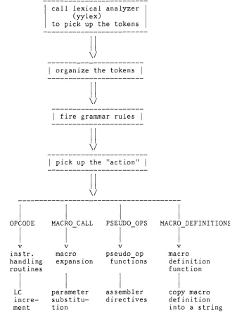
yyparseO in the main program, is produced
by
Yacc as a parser tocontrol the input process
(see
Figure 1 and Figure 2). When it iscalled, it in turn repeatedly calls yylex() to obtain input tokens.
These tokens are organized according to the M68000 assembly
language grammar rules. If one of these rules is recognized, some
C routines are invoked to accomplish the rest of the assembler's
jobs symbol table management, macro processing, code generation
Parser
(in
the case of pass 1):call lexical analyzer
(yylex)
to pick up the tokens
V
organize the tokens
V
fire grammar rules
V
pick up the "action"
OPCODE
v instr.
handling
routinesLC
incre
ment
V
MACRO CALL PSEUDO OPS
v
macro
expansion
parameter
substitu
tion
pseudo_op functions
assembler
directives
MACRO DEFINITIONS
v
macro
definition
function
copy macro
definition
into a string
[image:15.539.105.432.100.544.2]- 8
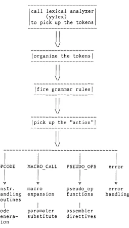
-Parser
(in
the case of pass2)
call lexical analyzer
(yylex)
to pick up the tokens
\/
|
organize the tokensV
fire grammar rules
\/
pick up the "action"
\/
OPCODE MACRO CALL PSEUDO OPS error
v V V v
instr. macro pseudo op error
handling
expansion functionshandling
routinescode paramater assembler
genera substitute directives tion
[image:16.539.161.416.100.548.2]- 9
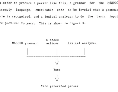
In order to produce a parser like
this,
a grammar for the M68000assembly
language,
executable code to be invoked when a grammarrule is recognized, and a lexical analyzer to do the basic input
are provided to yacc. This is shown in Figure 3.
M68000 grammar
C coded
actions lexical analyzer
\/
Yacc
\/
Yacc generated parser
Figure 3.
Generating
ofParsing
FunctionYacc processes the M68000 grammar along with the actions into the
parsing function yyparseO, and writes it out as a C function. The
parser and the lexical analyzer are compiled and linked together
with other C routines, and executed.
2.3 Interface Specification.
2.3.1 External Interfaces.
The assembler in its default mode provides assembly of instructions
for the MC68000 processor.
However,
the assembly of MC68008.MC68010, and MC68020 instructions can be enabled from the command
line. For example, if a MC68020 instruction set is
desired,
the [image:17.539.80.471.56.360.2]- 10
-mas -2 -1 source_file
where -2 selects the MC68020 machine instruction and -1 requests an
assembly listing.
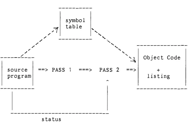
The cross-assembler could be executed under any operating systems
which has C compiler.
source program
==> PASS 1
status
Figure 4. Internal and External Interfaces.
2.3.2 Internal Interfaces.
The internal interfaces between two passes are the execution status
and the symbol table generated
by
Passl(Figure
4). A successfulexecution of Passl returns a status of
0,
however,
any syntacticerrors detected
by
parserduring
Passl or a symbol table overflowcause a non-zero value to be returned. If a non-zero status
occurred, the assembler displays any error messages at the terminal
[image:18.539.120.451.208.431.2]- 11
2. 4 Module Designs.
Top-down
development,
also known as modulardevelopment,
isconsidered as a very important design concept in
developing
thealgorithms of this assembler. It offers efficiency, reliability
and
flexibility
of design and makes the job ofincorporating
additional features and changes easy. Table 1 lists all the
modules that comprise the cross-assembler.
Global data structures
Parser Grammar with actions
Lexical analyzer
Instructions
handling
routinesWord extension
Symbol table management
Macro processor
Input
handling
routinesMacro expansion
Output
formatting
Error
handling
routines yyerror, and error messageString handling
Table 1. Module Design
This chapter describes the techniques used to implement each of the
above mentioned modules. Where appropriate pseudo code will be
12
-not
important
in understanding the logic of a routine.2.4.1 Lexical Analysis
The process
by
which the contents of input characters are convertedinto the form that is used within the translator is called Lexical
Analysis.
Every
time the Lexical Analyzer is called it returns anumber that represents the kind of token read. The communication
between the parser and the lexical analyzer is through a variable,
which is assigned the information associated with that token. The
type of token determines which data structure is to be used when
accessing the variable.
(see
Figure 7 for the data structure ofeach token type.
)
The major types of token in MC68000 are words, numbers, and
operators, each of which can be further divided into few subtypes.
For example, a word may be a reserved word
(e.g.
"MACRO" for macrocalls), an opcode
(e.g.
"MOVE"instruction),
or an identifier.The determination of "MACRO" as a reserved word can be done
by
either the parser or the scanner. Because the distinction between
lexical and syntactic analysis is not
firm,
one way to scan text isto include scanning as part of the parsing. This is accomplished
by
using a grammar whose terminal symbols are the charactersthemselves. Some substantial effort is needed to transform the
entire grammar into a suitable form for recursive descent without
backtracking.
However,
if the grammar which describes the lexicalanalysis is simple enough, such as MC68000 assembly
language,
aparticularly efficient scanner can be designed.
13
each token from its neighbors. In
MC68000,
a token is delimitedby
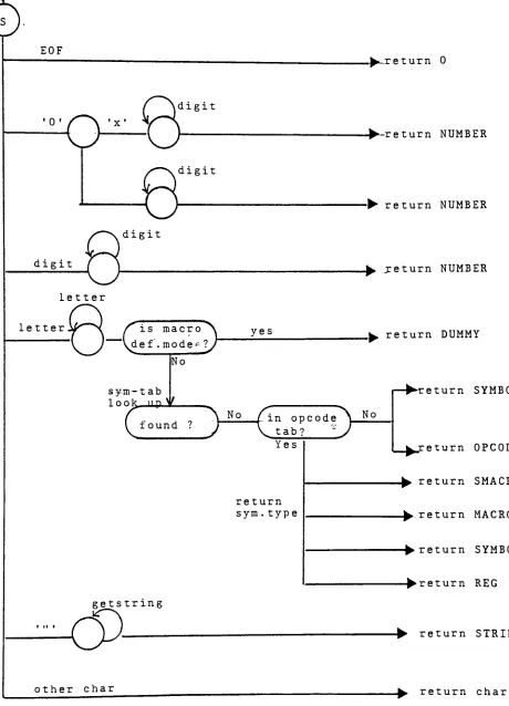
any nonalphabetic, nonnumeric character. Figure 5 is the state
diagram which describes the scanning process for MC68000 lexical
analyzer. All the token types returned
by
the lexical analyzer areshown on the right.
Generally,
the scanner skips blanks andtabs,
converts strings ofdigits into a numeric value, looks up the symbol table and the
opcode table to determine the token type of an ASCII string, and
return any other character as itself.
The identification of each character is in principle trivial. The
state diagram is to be studied carefully to ensure that the lexical
classes are properly defined. Also, a character recognizer which
fetches the next input character and discards comments and
nonsignificant blanks is necessary for the scanner.
2.4.2
Parsing
Before generating code, the translator must determine the content
of the source-language text to be translated. A lexical analyzer
is required to separate the source-language text into the elements
of which the language is composed. Syntactic analysis is required
to ascertain the structural relationships among those elements.
Much knowledge has been developed about parsing programs;
however,
to write a parsing function is difficult and is not our intention
here. The UNIX system has provided a very powerful
compiler-writing system yacc to
help
compiler writing. Yacc is a parsergenerator which serves the specification of a grammars
input
andEOF
^.return 0
0'
^""^
'x'digit
digit
digit
digit
letter
letter
/is
macro~\
~~~
\d ef. m ode<=
?/
No
sym-tab
1 nnV up v
yes
-?-return NUMBER
-? return NUMBER
_? return NUMBER
return DUMMY
>
"^ v/ v
r
- , o\Jl
/in
opcode\_JIi
I round ? > v .. w 'i J
Yes
return sym. type
eturn SYMBOL
return OPCODE
? return SMACRO
^return MACRO
-?return SYMBOL
-?return REG
getstr
ing
-? return STRING
other char
[image:22.539.41.501.52.690.2]- 14
-associate meanings with the components of the grammar in such a way
that as the parsing takes place, the meaning can be evaluated as
well.
The yacc user has to prepare a specification of input process; this
includes a grammar, a lexical analyzer,and the code to be invoked
when grammar rule is recognized. Yacc then generates a parsing
function to control the input process. This parsing function calls
the lexical analyzer to pick up the tokens from the input stream.
These tokens are organized according to the grammar rules; when one
of these rules has been recognized, then user supplied code for
this rule is invoked.
The advantage of yacc is that the parser generated
by
yacc issmall, correct and efficient; many nasty parsing problems are taken
care of automatically. The error
handling
in yacc is provided aspart of the input specifications which permits the reentry of bad
data,
or the continuation of the input after skipping over the baddata.
For an assembly language like
MC68000,
the syntactic analysis israther simple compared to that performed in a compiler.
(The
structure of address mode expressions must be specified, keyword
parameters must be distinguished from positional.) This is because
the syntax of assembley language is constrained to be simple;
interline syntax is particularly restricted. It is true that an
MC68000 assembler may have to face address expressions and macro
calls, both of which are rather complex. These are,
however,
rarely- 15
-It is
customary
to use the notation of BNF in representing agrammar. The
following
is the yacc BNF format for MC68000 assemblylanguage. module line module line line label stmt
: label stmt /* blank
*/
I*blank
*/
error /* blank "/
{
yyerrok;}
label SYMBOL ":"
{
if(undefined($2))
$2->sy_numb = pc;} OPCODE addrlist{
(*($1->sy_func))($1,$2);}
MACRO paralist{
expmacro($1 ,$2)
;}
{
defmacro($2)
;}
addrlist: addr ',' addrlist
{
$$
=addlistO
}
|
addr{
$$
=addlistO
}
dummlist: /* this is for macro definition
*/
paralist: /" this is for parameter list for macro
*/
/"
addressing mode starts here
*/
addr : REG /* Dn
*/
{
$$.ad_reg
= $1->sy_numb ;$S.ad_mode =
0;
}
|
"("REG")" /*(An)
*/
{
$$.ad_reg
=$1->sy_numb;
$$.ad_mode =0;
}
'#"expr /* #<data>
*/
{
$$.ad_expr =$2;
$$.ad_mode =11 ;}
/" addressing mode ends here*/
expr : NUMBER
- 16
{
$$.ex_symb
= $1 ;$$.ex_numb
=$1->sy_numb;
}
expr "+" expr
|
"-"expr
j
Characters between two braces are not parts of BNF but are,
instead,
the notations for yacc to indicate which actions should beexecuted after a certain grammar rule is recognized.
The grammar is later used for determination whether a given string
is in the MC68000 language. The determination of its structure is
called parsing. The task of parsing is to apply a grammar like the
above to a source MC68000 language program and determine the tree
structure which represents its syntactic structure.
2.4.3 Symbol Table Management
A symbol table is used to hold the meanings associated with user-defined symbols. The meaning of a symbol is expressed
by
means ofits attributes. Possible attributes are source-text line number,
types, value, and pointer to other data structures.
(
see Figure 8for example
)
The first reference to a symbol serves as an declaration and
inserts the symbol into the table. This access occurs an insertion
of the attribute.
However,
most accesses retrieve attributes.Retrievals require a search for the designated symbol; in practice,
insertion also require such a search. Because of these frequent
-17
-A
binary
search is quite efficient, but it requires that theelements of the array be sorted. This means that the enter
subroutine would have to adjust the table for each new entry, so
that the table was always sorted into the correct order.
Thus,
although a
binary
search might be quick, the combination of abinary
search plus an ordered enter might be very expensive.Another alternative is hashing. Different
hashing
functions can beused. For example, we can add together the character codes for the
different characters of the symbol, or multiply
them,
or shift someof them a few bits and exclusive-or them with the other characters,
or whatever we wish.
The objective of all this calculation is to arrive at an address
for a symbol which
hopefully
is unique for each symbol. But sincethere are millions of 10-character symbols and only a few hundred
table entries, collisions occur. The problem with using
hashing
isdefining
a goodhashing
function;
a good hash function will resultin very few collisions.
Consider that a linear search is efficient for small tables.
Many
assembly language programs have less than 200 different symbols,
and so a linear search may be quite reasonable. This is why linear
search is used in our symbol table management. A linear search
allows the enter routine to simply put any new symbol and its value
at the end of the table.
Thus,
both the search and enter routines- 18
2.4.4 Macro
Processing
A straightforward implementation of the macro processor is to add
another pass to an existing assembler to expand all macros.
Thus,
an existing two-pass assembler can be converted into a three-pass
macro assembler. The first pass expands all macros, the second
pass defines the symbol
table,
and the third pass generates theoutput.
The macro expansion pass copies all assembly language statements
except macro definitions and macro calls. A macro definition is entered into the macro name
table,
and the assembly languagestatements which follow are stored in the macro definition string
until an closing delimiter is encountered.
During
pass 2 when amacro call is encountered, the corresponding prototype is found
by
following
a pointer which was placed in the symbol table when thedefinition was collected
during
pass 1 . Parameter substitution isperformed as the macro definition is copied out.
The advantages of this three-pass division are that space
requirements are modest and that forward references are permitted.
However, forward references to macro definitions in the input text
are not as important as forward references to symbols in
assembler-language text, because requiring macros to be defined
before use makes no hardship.
Passing
the text twice then incursunnecessary cost. Therefor, in this project, a two-pass macro
assembler is implemented.
When the opening delimiter of a macro definition
(in
our assemblera
".macro"
-19
-formal parameter in the
body
of definition is replacedby
a numberwhich gives the position of the formal parameter in the parameter
list. A pseudo-function to do this is described as follows:
def_macro(sym
list)
7"copy the definition into macro_def_string
*/
/x
keep
the list of macro name and dummies*/
get macro nameput macro name on symbol table
get
dummy
arguments and prepare adummy
listinitial a string buffer for definition
while
(not EOF)
get symbol
while
(not
EOLN)get symbol
if it is
dummy
get index notation from
dummy
list and substitute endend
(EOF)
put address of string into symbol_table
end
Meanwhile,
the macro name and the pointer of its definition stringare stored in symbol table marked "macro" to distinguish macro
calls from other instructions.
2.4.5 Code Genera tion
MC68000 instructions are of variable length. For each instruction
in the MC68000 instruction set there is one corresponding
instruction
handling
routine in the code generation module, eachhandling
routine is passed two parameters: the opcode itself andthe operand list. The instruction routine increments the location
counter properly in Pass 1 , and generates the code and the
extension words for the instruction in Pass 2.
The value added to the location counter depends on the
instruction
20
-using the effective address field in the operation word. The
effective address is composed of two fields: the addressing mode
field and the register field. It may require additional
information for the effective address field to
fully
specify theoperand. The additional information is contained in one or a few
following
extension words(depends
on the addressing mode).During
Pass1,
the instructionhandling
routine simply gets thesource and destination addressing mode of the operands from its
second parameter
(operand
list)
and determines the value to beadded to the location counter.
During
Pass2,
the location counter is advanced just asduring
Pass1 . Each field in the operation word, such as source and destination
registers, source and destination modes and instruction size(.L, .W
or .B) is inserted into the operation word for code generation.
Extension words for MC68000 instructions may be immediate operand,
branch
displacements,
extensions to the effective address modespecified in the operation word, bit number specifications, special
register specifications,
trap
operands or argument counts. Seeappendix A for the extension word requirements for MC68000.
2.5 Data Bases.
The Data Bases in the assembler are:
Input source program
Location Counter - Used to
keep
track of eachinstruction's
21
Symbol Table Used to
keep
each symbol encountered along with itscorresponding value. Notice that the macro name,
registers, and other system defined symbols are also
considered as "symbols" in this assembler, so
they
arestored in the symbol table too.
Opcode Table - Each Opcode Table
entry contains the symbolic
opcode, the pointer to its instruction
handling
routine andis operation size. Pseudo-ops are kept here also.
String
Buffer - Used to hold series of symbols like macrodefinitions and quoted Ascii strings.
Input File structure - A structure that contains pieces of
information about the input file: a pointer to a
buffer,
apointer to the next character, a count of the characters
left,
and the file descriptor.Data Structures for each token type - Structures for terminals:
Symbol for token type
SYMBOL,
Number for token type NUMBERand
String
for token type STRING. Structures for thenonterminals: Addr for addressing mode, Expr for
expression, and List for string of symbols.
An assembler must translate two different kinds of symbols:
assembler-defined symbols which are mnemonics for the machine
instructions and pseudo-instructions; and programmer-defined
symbols which are the symbols defined in the label field of
statements
by
the programmers. These two kinds of symbols aretranslated
by
two different tables: the opcode table and the symbol- 22
-In one way,
they
are quite alike:they
both translate symbols intoproper numeric equivalents which are accepted
by
the machine.Thus,
in this assembler,
they
are designed with the same data structurefor their table entries
(Figure
6-1 and 6-2).Also,
by
generalizingthe table
formats,
the opcode tabel and pseudo-op table arecombined into one table.
symbolic symbol value Address Pointer
name types of routine
to process instruction to macro definition string "XYZ" HTlII SYMBOL MACRO UND 0 NULL NULL NULL 234123
Figure 6-1 Symbol Table
symbolic symbol value Address Pointer
name types of routine
to process instruction to macro definition string "ADD"
OPCODE 0 add
"MOVE"
OPCODE 0 move
"UNPK"
OPCODE 20 unpk
NULL NULL NULL
Figure 6-2 Opcode Table
The field "Address of routine to process instruction" contains a
value only when the symbol is an instruction.
The field "Pointer to macro definition string"
contains a value
23
-type of instruction set
(0
forMC68000,
20 for MC68020).By
default,
the values returnedby
the lexical analyzer areintegers. In order to allow tokens return sufficient information
about themselves it is necessary to make the values of specific
data structures. The followings
(Figure 7)
are the data structureformats for the terminal and nonterminal token types.
Symbol(terminal):
symbolic
name
symbol
types
value Address
of routine
to process
instruction
Pointer to macro
definition string
Number(terminal):
- 24
-Address
(nonterminal)
base displace
ment
address
register
index
register
addressing
mode
outer
displace
ment
Base displacement and Outer displacement both contain a pointer
to an
Expr-Address register contains 2 fields: register numb and register
size
(only
for implicit PC mode).Index register contains 3 fields: index register number, size
and scale.
Expression(nonterminal):
value
List(nonterminal):
pointer
to next
item
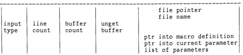
The
following
is the data structure that describes the input file.It contains the most important messages about input function such
25
Input:
input
type
line
count
buffer
count
unget buffer
file pointer file name
ptr into macro definition ptr into current parameter
list of parameters
input type is either MACRO or FILE.
line count keeps track of input line number.
buffer count is the number of characters left in unget buffer.
unget buffer is the buffer for unget characters.
the last field is either for regular FILE information or for MACRO information.
Figure 7. Data Structure Formates
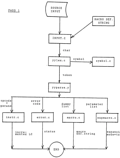
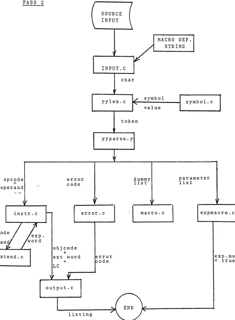
2.6 Communications among Modules.
The communications among each module are shown in Figure 8-1 and
[image:34.539.77.480.83.175.2]PASS 1
SOURCE
INPUT
opcode +
operand
V
instr. c
error code
V
MACRO DEF
STRING
L
INPUT. C
V
char
yylex. c symbol
->
symbol . c
token
yyparse. y
dummy
list
error . c
incre mented LC
parameter list
r
macro. c
status
1
expmacro. c
macro
def. string
[image:35.539.38.494.24.623.2]PASS 2 SOURCE INPUT opcode + operand
instr . c
ode
an
exp
'word
ixtend . c
MACRO DEF
STRING
INPUT.C
char
yylex. c
<r
symbol
value
token
yyparse. y
error
code
dummy
listerror . c
objcode
-r
ext word
+
LC
macro . c
error code
output . c
list
ing
symbol . c
parameter list
expmacro . c
exp . mode
[image:36.539.23.507.42.701.2]- 26
-3. VERIFICATION AND VALIDATION.
3.1 Test Plan.
Since exhaustive
testing
isimpossible,
a carefully selected set ofdata can greatly ease the problem of
detecting
errors. In the stageof the system development we use a simple test data set to test all
possible program logic paths. For example, in
testing
the lexicalanalyzer we were concerned if the returned token type was correct;
a small set of token types was adequate for this test.
However,
the goal of this test plan is to ensure that the systemsolves the problem that it is supposed to solve and that it yields
the correct answer under all conditions
by
means of a scientificaltesting
methodology. We will concentrate ondiscussing
systemtesting. The
testing
of the system is performedby
several testprocedures.
3.2 Tes t Procedures.
3.2.1 Instruction set
A. Collect a complete set of instructions for 68020. the test
27
-move d0,a0 add dO,aO
bra start
nbcd dO
rts
nop
end
B. Assemble the test data and validate the result to see there
is any illegal instruction value of instruction code.
C. Assemble the test data for all target machines to see there
is any illegal instruction.
3.2.2 Address mode
A. Select test instructions so that each instruction represents
a class of instructions. For example:
addi, andi, ori, subi, etc..
bcc,
bcs,
beq,
bge,
etc..divs,
divsl,
divu,
divul,
etc..- 28 addi addi addi addi addi addi addi addi addi addi addi
0x55,
d10x55,
a10x55,
(a2)
0x55,
(a3)+
0x55,
-(aA)0x55,
(1
0000,
a5)0x55,
(100,
a5,d2)0x55,
(1000000,
a5,d2)0x55,
(
[
1 000000,a5,d2]
,0x40)
0x55,
(
[
1000000
,a5]
,d2,0x40)
0x55,0x40
eor d2,d3
eor
d2,(a1)
eor d2,(a1)+
eor
d2,
-(a1)
eor
d2,
(10000,
a5) eord2,
(100,a5,d2)
eor d2,(1
000000,
a5,d2)eor
d2,([
1000000,
a5,d2],0x40) eord2,
([1000000,
a5],d2,0x40)
eor d2,0x40
B. Assemble the test data for all target machines to see there
is any illegal addressing mode value of instruction code and
extension words
3.2.3 Instruction size
A.
Modify
the size of instructions in the test data ofaddressing mode
(i.e.
replace eor with eor.b, eor.w or eor.letc.
)
.B. Assemble the test data for all target machines to see there
is any illegal instruction size value of instruction code and
- 29
-3.2.4 Pseudo code
A. Add all pseudo operation into the test data of addressing
mode
(i.e.
org,ds,
dc,
equ,list,
etc.)B. Assemble the test data for all target machines and validate
the result of location counter, data storage, symbol table.
3.2.5 Macro definition and Macro call
A. Add macro definition and macro call into the test data of
addressing mode
B. Assemble the test data for all target machines and validate
the result of location counter, data storage, symbol
table,
output
listing
and the value of expanding macro codes.3.2.6 Error
handling
A. This test procedure should include all the error
detecting
such as redefined symbol, undefined symbol, symbol table
overflow, invalid value for expression, illegal register,
etc. .
3.3 Test Results.
- 30
-4. CONCLUSIONS.
4.1 Problems Encountered and Solved.
In traditional two-pass assembler an
intermediate
file is generatedfor pass 2 to save time of redoing macro call expansion. In order
to speed up the assembling time we eliminated the intermediate
file.
During
pass 2 whenever macro call expansion is needed ,system directs input routine to macro definition string instead of
source file.
4.2 Discrepancies and Shortcomings of the System.
Users must specify all the user-specified values such as base
displacement(bd)
, index register, scale, base register, programcounter and outer
displacement(od)
in 68020.The format of object codes is not suitable for commercial eprom
programmers.
The format of a register list has to be d0/d1/-../d6 instead of
d0-d6.
Due to the unclear definition in M68020 manuals of how to handle
pc-relative mode in pc indirect with index addressing mode and pc
memory indirect modes in
68020,
pc-relative mode is not allowed inthese addressing modes.
This is a non-optimizing assembler;
i.e.,
you have to explicitly31
-4.3 Lessons Learned.
4.3.1 Alternative Approaches for Improved System.
The assembler should separate pseudo macros and pseudo directives
from the opcode table and put them into different tables. This will
not only improve search
time,
but will also decrease the size ofthe table
by
eliminating some unused data.The performance of the assembler can be improved
by
using ahashing
function to build up a symbol table.
4.3.2 Suggestions for Future Extensions
With a few additions
(such
as external symbol definition andmultiple location counters) this assembler can be easily upgraded
to a complete link-loader assembler. It will not be a completed
68020 assembler without coprocessor capability. It is possible to
add a coprocessor into this system as
long
as the specification ofcoprocessor is available.
4.3.3 Related Thesis Topics for the Future.
Conditional assembly, linkage editor, and high-level structure
assembly may very well be some related thesis topics for the
- 32
-Bibliography
Aho,
A.V. andUllman,
J.D. TheTheory
ofParsing,
Translation,
andCompiling.
Prentice-Hall,
EnglewoodCliffs,
M.J. 1972Barron,
D.W. Assembler andLoaders,
2nd ed.Macdonald,
London.Calingaert,
P.Assemblers,
Compilers,
and Program Translation. NewYork,
1979Christian,
K. The UNIXOperating
System.Wiley,
NewYork,
1983Gries,
D. Compiler Construction for Digital Computers. Wiley, NewYork,
1971Kernighan,
B.W. The UNIXProgramming
Environment.Prentice-Hall,
Englewood Cliffs, N.J. 1984
Motorola,
M68000 16/32-Bit Microprocessor Programmer's ReferenceManual. 4th Ed. Prentice-Hall, Englewood Cliffs, N.J. 1984
Motorola, MC68020 32-Bit Microprocessor User's Manual. 2nd Ed.
Prentice-Hall, Englewood Cliffs, N.J. 1985
Short,
K.L. Microprocessors and Programmed Logic. Pentice-Hall,33
-Appendix A. Extension Word Requirement
assembly notation
mode MC68000 MC68020 extension word
101
d16(An)
(d16,An)
16-bit Displacement110
d8(An,Xi)
(d8,An,Xi)
Combined Index Descriptor/ Displacement Word(bd,An,Xi)
Full Format Descriptor/Base-Outer Displacement
( [bd,
An],Xi,od) see above(
[bd,An,Xi]
,od) see above111 d16(PC)
(d16,PC)
16-bit Displacement111 d16(PC,Xi)
(d8,PC,Xi)
Combined Index Descriptor/Displacement Word
111 -
(bd,PC,Xi)
see above111 -
([bd,PC],Xi,od)
see above111 -
([bd,PC,Xi],od)
see above111 Z/xxx #xxx 1 or 2 words
depending
upon the operation size
111 xxx.L xxx.L 2 extension words
-1st, high part of const -snd, low part of const
34
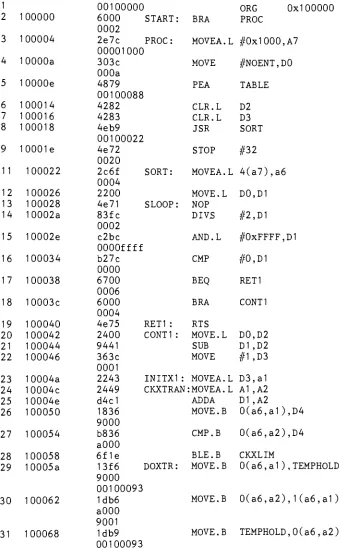
-Appendix B. EXAMPLE OUTPUT LISTING
EXAMPLE OUPUT LISTING FOR MC68000
1 2 100000 3 100004 4 10000a 5 10000e 6 100014 7 100016 8 100018 9 10001e 11 100022 12 100026 13 100028 14 10002a 15 10002e 16 100034 17 100038 18 10003c 19 100040 20 100042 21 100044 22 100046 23 10004a 24 10004c 25 10004e 26 100050 27 100054 28 100058 29 10005a 30 100062 31 100068
00100000
i ORG 0x1000006000 START: BRA PROC
0002
2e7c PROC: MOVEA.L #0x1
000,
A700001000i
303c MOVE
#NOENT,D0
000a
4879 PEA TABLE
00100088
4282 CLR.L D2
4283 CLR.L D3
4eb9 JSR SORT
00100022
4e72 STOP #32
0020
2c6f SORT: MOVEA.L 4(a7),a6
0004
2200 MOVE. L D0,D1
4e71 SLOOP: NOP
83fc DIVS
#2,D1
0002
c2bc AND.L #0xFFFF,D1
OOOOffff
b27c CMP #0,D1
0000
6700
BEQ
RET10006
6000 BRA CONT1
0004
4e75 RET1 : RTS
2400 CONT1 : MOVE. L D0,D2
9441 SUB D1 ,D2
363c MOVE
#1,D3
0001
2243 INITX1 : MOVEA.L D3,a1 2449 CKXTRAN:MOVEA.L A1 ,A2
d4d ADDA D1 ,A2
1836 MOVE. B 0(a6,a1
),D4
9000
b836 CMP.B 0(a6,a2),D4
aOOO
6f1e BLE.B CKXLIM
13f6 DOXTR: MOVE.B 0(a6,a1
),TEMPHOLD
9000
00100093
1db6 MOVE. B
0(a6,a2),1(a6,a1)
aOOO
9001
[image:45.539.72.421.125.677.2]35
-aOOO
32 100070 92c1 NXTXLOW:SUBA D1 ,A1
33 100072 b2fc
0000
CMPA
#0,A1
34 100076 6dd4 BGT.B CKXTRAN
35 100078 d67c
0001
CKXLIM: ADD
#1,D3
36 10007c 3a03 MOVE D3,D5
37 10007e 9a42 SUB D2,D5
38 100080 ba7c
0000
CMP
#0,D5
39 100084 6da2 BGT.B SLOOP
40 100086 5fc2 BRA.B INITX1
42 100088 5a TABLE: DC.B 'Z'
43 100089 Oa DC.B 10
44 10008a 09 DC.B 9
45 10008b 08 DC.B 8
46 10008c 07 DC.B 7
47 10008d 06 DC.B 6
48 10008e 05 DC.B 5
49 10008f 04 DC.B 4
50 100090 03 DC.B 3
51 100091 02 DC.B 2
52 100092 01 ENDTAB: DC.B 1
53 0000000a NOENT: EQU END TAB
--TABLE
54 100093 0001 TEMPHOLD: DS.B 1
55 END
""
TOTAL ERRORS ** 0
SYMBOL TABLE START 100000 PROC 100004 NOENT a TABLE 100088 SORT 100022 SLOOP 100028 RET1 100040 CONT1 100042 INITX1 10004a CKXTRAN 10004c CKXLIM 100078 DOXTR 10005a TEMPHOLD 100093 NXTXLOW 100070
36
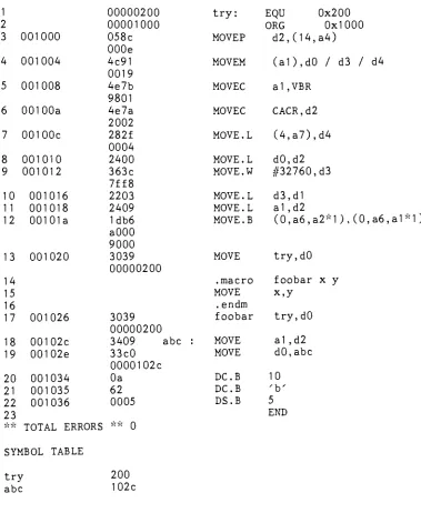
-EXAMPLE OUPUT LISTING FOR MC68020
1 00000200 try: EQU 0x200
2 00001000 ORG 0x1000
3 001000 058c
OOOe
MOVEP
d2,(14,a4)
4 001004 4c91
0019
MOVEM
(a1),d0
/
d3/
d45 001008 4e7b
9801
MOVEC a1 ,VBR
6 00100a 4e7a
2002
MOVEC CACR,d2
7 00100c 282f
0004
MOVE. L (4,a7),d4
8 001010 2400 MOVE.L d0,d2
9 001012 363c
7ff8
MOVE.W
#32760,
d310 001016 2203 MOVE.L d3,d1
11 001018 2409 MOVE. L a1,d2
12 00101a 1db6
aOOO
9000
MOVE.B (0,a6,a2-1),(0,a6,a1
*D
13 001020 3039
00000200
MOVE try,d0
14 .macro foobar x y
15 MOVE x,y
16 . endm
17 001026 3039
00000200
foobar try,d0
18 00102c 3409 abc : MOVE a1 ,d2
19 00102e 33c0 0000102c
MOVE d0,abc
20 001034 Oa DC.B 10
21 001035 62 DC.B 'b'
22 001036 0005 DS.B 5
23 END
** TOTAL ERRORS; ** 0
SYMBOL TABLE
try
200 [image:47.539.69.448.77.548.2]- 37
Appendix C. USER MANUAL
C. 1 SOURCE PROGRAM CODING.
C. 1 . 1 Commen ts.
A comment may be inserted at the
beginning
of a line.Examples:
|
This entire line is a comment.C.1.2 Executable Instruction Format.
Each source statement has an overall format that is some
combination of the
following
four fields: a. label b. operation c.operand d. comment.
a. Label Field A label starts in any column and terminates with
a colon
(
:)
.b. Operation Field The operation field follows the label field
and is separated from it
by
at least one space. Entries inthe field fall under one of the
following
categories:Operation codes which correspond to the MC68000
series instruction set.
Directives pseudo-operation codes for controlling the
assembly process, and macro calls for
inserting
apreviously-defined macro.
The size of the data field effected
by
an instruction isdetermined. Some instructions can operate on more than one
data size. For these
instructions,
the data size code must- 38
-assumed. The data size is specified
by
a period(.),
appended to the operation code, and followed
by
B(byte),
W(word),
or L(long
word).c. Operand Field
When two or more operand subfields appear within a
statement,
they
must be separatedby
a comma.C.2 EXPRESSIONS.
An expression is a combination of symbols, constants, algebraic
operators, and parentheses. The expression is used to specify a
value which is to be used as an operand. The operators in the
assembler are:
+ ,
-,
*
,
/
, and unary minus.C.3 SYMBOLS.
A symbol is a string of alphanumeric characters, whose first
character is alphabetic. The symbols A0-A7,
D0-D7,
CCR,SR,SP,USP,CACR,CAAR,VBR, SFC and DFC are special symbols used
by
the assembler, and cannot be used in the label field.Some of the expressions cannot be evaluated
during
the first passbecause
they
may contain references to symbols which have not yetbeen defined. If a symbol is not defined before
being
used in the
-39
-C.4 NUMBERS.
A number may be used as a term of an expression or as a single
value. A number may assume any of the
following
formats:Decimal Hexadecimal
Octal
ASCII
C.5 REGISTERS.
a string of decimal digits, ex. 2321
Ox followed
by
a string of hexadecimal digits.ex. 0x34fa
a 0 followed
by
a string of octal digits, ex. 02344a string of ASCII characters enclosed in apostrophes,
ex. z'
The
following
registers are recognizedby
the assembler:d0-d7,D0-D7 a0-a7,A0-A7 a7,A7,SP SR CCR CACR CAAR VBR
DFC,
SFC Data Registers Address RegistersSystem stack pointer of the active system state.
Status Register
Condition Code Register
Cache Control Register
Cache Address Register
Vector Base Register
Destination and Source Function Code Registers
C.6 VARIATIONS OF INSTRUCTION TYPE.
Certain instructions
(ADD,
AND, CMP,MOVE, NEG,
OR,and SUB) allowvariations in their basic opcodes. The variations are recognized
by
a single letter suffix appended to the opcode: A(for address),l(for immediate), Q(for quick), M(for memory), and X
(for
extend).If one of these forms was
desired,
the programmer has to declare itexplicitly.
C. 7 ADDRESSING MODES.
- 40
-C.8 ASSEMBLER OUTPUT.
Assembler outputs include an assembly
listing,
a symbol table , andan object code file. An example of assembly
listing
is given inthe appendix B.
C.9 ASSEMBLER DIRECTIVES.
ORG The ORG directive changes the program counter to the value
specified
by
the expression in its operand field.ORG <expression>
END The END directive indicates to the assembler that the source
is finished. Subsequent source statements are ignored.
END
EQU The EQU directive assigns the value of the expression in the
operand field to the symbol in the label field.
<label> EQU <expression>
DC The function of the DC directive is to define a constant in
memory.
DC.B <operand>
DS The DS directive is used to reserve memory locations. The
contents of the memory reserved are not initialized in any
way.
DS.B <operand>
LIST Print the assembly
listing
on the output device.- 41
NOLIST Suppress the printing of the assembly listing.
NOLIST
NOOBJ Suppress the generation of object code.
NOOBJ
C. 10 DEFINING A MACRO
The definition of a macro consists of three parts: the
header,
thebody
and the terminator.Example: .macro TAG a,b,c
ADD a,D1
ADDX b,D1
SUB c,D1
. endm
The header contains the macro name which is TAG and the
dummy
arguments a,b,c. The
body
contains the pattern of sourcestatements. The terminator is the .endm directive.
In this assembler the nesting of macro definition is not permitted.
C. 1 1 CALLING A MACRO
The macro call statement is made up of two basic fields: the
operation field
(containing
the macro name) and the operand field(containing
substitutable values).Example: TAG A0,A1 ,A2
C. 12 INVOKING THE CROSS ASSEMBLER
The command line format for the assembler is:
- 42
-The assembler recognizes the
following
options on the command line:-o produce object
code
-1 produce
listing
The machine types are:
-0 accept MC68000 machine instruction set
(default)
-8 accept MC68008 machine instruction set
-1 accept MC68010 machine instruction set
-2 accept MC68020 machine instruction set
Example: mas -0 -1 -o input.mas
The file name of the object code is objcod. The
listing
file iscalled outlis.
C. 13 ERROR CODES
203 IMPROPER TERMINATION OF OPERAND FIELD the operand field is
not terminated correctly.
205 SIZE SUBFIELD NOT ALLOWED FOR THIS OPCODE this opcode does
not allow the specified size of
B,
W,
or L.208 DISPLACEMENT RATE
(SIZE)
ERROR the number of bytes betweenthis instruction and the address referenced is too large.
209 ILLEGAL ADDRESS MODE FOR THIS INSTRUCTYION an illegal
address mode has been used for this type of opcode.
219 TOO MANY OPERANDS FOR THIS INSTRUCTION more operands are