Grid Virtualization Engine: Design, Implementation
and Evaluation
Lizhe Wang,
Member, IEEE,
, Gregor von Laszewski,
Member, IEEE,
, Jie Tao and Marcel Kunze
Abstract— Virtual machines offer various advantages such as easy configuration, management, development and deployment of computing resources for cyberinfrastructures. Recent advances of employing virtual machines for Grid computing can help Grid communities to solve research issues, for example, QoS provision and computing environment customization. The heterogeneous virtualization implementations, however, bring challenges for employing virtual machine as computing resources to build Grid infrastructures. The work proposed in this paper focuses on building a Web service based virtual machine provider for Grid infrastructures. The Grid Virtualization Engine (GVE) creates an abstract layer between users and underlying virtualization technologies. It implements a scalable distributed architecture in a hierarchical flavor.
The GVE Site Service provides Web service interfaces for users to operate virtual machines, thereafter building Grid infrastructures. The underlying GVE Agent Service talks with different virtualization products inside the computing center and provides virtual machine resources to the GVE Site Service.
The GVE is designed and implemented with the state of the arts of distributed computing technologies: Web service and Grid standards. The GVE is evaluated with CMS benchmark, a high energy physics application from CERN. In addition to the GVE design and implementation, this paper also uses a real example to illustrate how to apply the GVE to build an e-Science infrastructure at runtime. By providing experiments, tests and a use scenario , we show the GVE is an efficient and lightweight middleware for building grid infrastructures with virtual machines.
Index Terms— Grid computing, virtual machine, virtual com-puting environment
I. INTRODUCTION
GRID
Computing technology [9], [10] offers practical solutions for parallel and dis-tributed computing. It can provide reliable, collaborative and secure access to remote computational resources as well as distributed data and scientific instruments. Although great advances have been made in the field of Grid computing, users still expect to meet some difficulties when employing Grid resources:• Qualities of Service (QoS) of resource provision and
performance isolation:A Computational Grid is a highly
dynamic environment in that resource capacities and
Manuscript received September 4, 2008; revised July 15, 2009. Work conducted by Gregor von Laszewski is supported (in part) by NSF CMMI 0540076 and NSF SDCI NMI 0721656.
Lizhe Wang is with Service Oriented Cyberinfrastructure Lab, Rochester Institute of Technology (email: [email protected]). Gregor von Laszewski is with Community Grids Laboratory, Indiana University at Bloom-ington (email: [email protected]). Marcel Kunze and Jie Tao are with the Steinbuch Centre for Computing, Karlsruhe Institute of Technology, Germany (email:{Marcel.Kune, Jie.Tao}.iwr.fzk.de).
access interfaces may change from time to time. Grid applications often compete for shared resources, thus preventing any QoS guarantee of resource provisions.
• Customized runtime environment for Grid applications:
In general, Grid applications demand customized exe-cution environments such as operating system, software packages & libraries, and network configurations. Some requirements of these runtime configurations need ad-ministration privileges, which are normally impossible to obtain in a Grid environment.
A virtual machine is a computing platform that creates a virtualized layer between the computing hardware and the application. Employing virtual machines as computing envi-ronments for Grid applications can address challenges above. In general, Grid users might benefit from the virtualization techniques in the following aspects:
• On demand creation and customization:Users can create
a customized virtual machine, which provides customized resource allocation for users, e.g., operating system, memory, storage, etc.
• Performance isolation: Virtual machines can guarantee
the performance for users and applications. Users of vir-tual machines can expect dedicated computing environ-ments, which are hard to find in multiple-user computing servers.
• Legacy software support: Customized virtual machines
which are compatible with legacy binary applications can be created. Users from specific application domains would find them very desirable and promising since some legacy libraries can be supported.
• Easy management: Users in general can only access
computing servers with restricted user privileges. It is thus difficult to process the work such as compilation, installation, and configuration of desirable computing en-vironment for users. Virtual machines on the contrary, can offer users with the “root” access of the allocated virtual machine. Therefore application domains can manage their environments in their own interests.
Virtual machine based Grid systems are characterized by some special features, which bring research challenges for deploying, monitoring and operating the system:
• Site autonomy: In a virtual machine based Grid system,
creation and manipulation of virtual machines.
• Hierarchy: A virtual machine based Grid system is
hier-archical in nature. It contains several levels: Grid level, virtual machine level, host resource level and the user access point, i.e., a Grid portal.
• Heterogeneity: A virtual machine based Grid system
includes heterogeneous host resources, various virtual machine technologies (e.g., Xen, VMWare) as well as multiple programming interfaces.
• Large scale distribution: Computing centers and data
centers frequently build Grid infrastructures across ge-ographically distributed sites.
To ease the deployment of virtual machine based Grid infrastructures, it is important to represent virtual machine profile in an industry standardized format, simplify the ac-cess to virtual machines provided by computer centers with standard and uniformed access interfaces, and build a ser-vice infrastructure that can provide virtual machines from multiple computer centers. We design and implement the Grid Virtualization Engine (GVE) to fulfill the foregoing objectives. The GVE is light weight distributed middleware, which enables users to operate virtual machines and provides virtual distributed environments across distributed computing centers. The GVE implements a Web service based abstract layer and can manage a set of virtual machines provided by heterogeneous VMMs located in distributed compute centers. Information provided for a virtual machine uses the standard-ized GLUE Schema [29]. This paper presents performance evaluation of GVE with the Compact Muon Solenoid (CMS) benchmark [24], a high energy physics application from CERN (European Organization for Nuclear Research). A real use scenario, involving the on-demand creation of an e-Science infrastructure, is discussed in this paper to demonstrate the GVE usage.
The rest of the paper is organized as follows. Related work is investigated in Section II. Section III defines the model of virtual machine based Grid system, in which the GVE is developed and deployed. Section IV describes the GVE architecture. In Section V, GVE use cases are discussed. This is followed by a description of the GVE implementation in Section VI. In Section VII and Section VIII, the GVE is tested with some experiments and is quantitively evaluated with the CMS benchmark. We present in Section IX a sample use scenario of the GVE – building an e-Science infrastructure with distributed virtual machines enabled by the GVE. The paper concludes in Section X with a brief summary and future work.
II. RELATED WORK
A Virtual Machine (VM) is a software artifact that executes other software in the same manner as the machine for which the software is developed and executed [21]. Virtual Machine Monitor (VMM) is a software that supports multiple virtual machines on the same resource. Typical VMMs or hypervisors include Xen VMM [2], VMware server/ESX server [37], and User Mode Linux [35].
Recently, the parallel and distributed computing research community has shown interest in virtual machines and virtual
computing environments. Some research work focuses on de-ploying computing systems or testbeds with virtual machines, for example, virtualization of batch queueing system [3], GridBuilder [4], using virtual machine as Grid gateway [5], multi-site MPI platform with Xen virtual machine [26]. Xen Grid Engine [6] follows an approach to create dynamic virtual cluster partitions using para-virtualization techniques. The work presented in [11], [19] builds virtual clusters and virtu-alized distributed infrastructures. OpenNebula [34] is an open source virtual infrastructure engine that enables the dynamic deployment and re-placement of groups of interconnected virtual machines.
These systems, however, are deployed in a small scale area network, for example, a cluster system or a computer site. Our work aims to work in a large scale distributed Grid infrastructure, which contains multiple computer centers and spans across multiple administrative domains. The GVE implementation solves a number of research issues, such as scalability, extensibility and multi-domain administration, which do not exist in a cluster or a LAN environment.
The Globus alliance recently implemented the concept of a virtual workspace and Nimbus [36], [12], which allows a Grid client to define computing requirements, manage computing environments, and deploy computing environments on a Grid. The implementation is based on Globus Toolkit version 4 and it only supports Xen VMM. Our implementation of GVE is developed with standard Web service technologies, such as XML, SOAP and HTTP, and it can support both Xen and VMware virtual machine. Web service technologies have various advantages over the Globus Toolkit implementation, for example, scalability, interoperability, legacy application support, and underlying platform independence. Therefore, our implementation gains more advantages by adopting standard Web service technologies.
The In-VIGO [1] project aims to build virtualization mid-dleware. In-VIGO provides a distributed environment where multiple application instances can coexist in virtual or physical resources such that clients are unaware of the complexity inherent to Grid computing. Amazon Elastic Compute Cloud (Amazon EC2) [27] is a Web service that provides resizable compute capacity with virtual machines. It is designed to make web-scale computing easier for developers. Eucalyptus [28] is a software infrastructure for implementing “cloud computing” on clusters.
Systems like In-VIGO, Amazon EC2 and Eucalyptus em-ploy Web service technologies and virtual machine operations in a large scale distributed environments. However, they do not aim to work on existing production Grid infrastructures and framework. Furthermore, there are still no reports of successful large scale scientific applications, e.g. high energy physics, deployed on these systems. Our implementation of GVE works on existing Grid infrastructures and adopts current Grid computing model. Killer applications of Grid computing, for example, CMS benchmark, is deployed and executed on Grid infrastructures with the help of GVE.
performance evaluation. In detail, compared with related work, the unique contribution of this paper includes:
• Defines a hierarchical virtual machine based Grid system model,
• Builds a scalable and efficient GVE service that can provide virtual machine resources to Grid system based on popular VMMs, e.g., Xen and VMware,
• Makes a performance evaluation on GVE and virtual machines with a non-trival application – the CMS bench-mark [24], which is a killer application for productional Grid computing from the Worldwide LHC Computing Grid (WLCG) project [16] at CERN, and
• Provides our experience of employing virtual machine
re-sources for Grid infrastructures by building an e-Science infrastructure on demand.
!""#$$%&#'()"#%
*)'+,-.%/-"0)1#%
23$+%4#$3,'"#% 5367,+-831-.%9'):$%
[image:3.612.113.232.251.450.2]5367,+#'%&)+#%
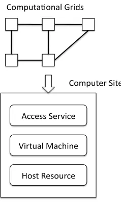
Fig. 1. Virtual machine based Grid system model
III. THE VIRTUAL MACHINE BASEDGRID SYSTEM
The GVE is a software layer between various virtualization implementations, computing centers and Grid users. Users can require and employ virtual machines via the access interface of GVE. The GVE talks with underlying computing centers and VMMs for virtual machine operations. Computer centers can also provide virtual machines to form Grid infrastructures. The employed virtualization technology may differ from one computing center to another (i.e VMWare and XEN technolo-gies). The GVE thus provides a standard and uniform access to virtual computing resources.
We propose a system model to describe a distributed, hi-erarchical, heterogeneous virtual machine based Grid system, which contains distributed Computer Sites (Computer Centers) interconnected by network (see also Figure 1).
Each Computer Site logically consists of the following levels:
• The Computer Site provides an access service which allows remote users to access resources of the computer center. The access service can be offered by existing Grid
middleware, a portal, Web services, or any functionalities that support remote steering. The GVE service is devel-oped and integrated in this level.
• In the middle level, virtual machines are backed by
host resources. These virtual machines form virtualized distributed environments. GVE service operates on virtual machines in this level.
• The fabric level contains various host resources or servers, which are installed with virtual machine hypervi-sors. Host resources offer multiple virtual machines. The GVE Agent Service is implemented in this level with aids of VMM APIs and SDKs.
IV. ARCHITECTURE OFGRIDVIRTUALIZATIONENGINE
A. Overview
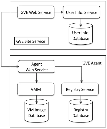
The GVE provides functionalities for users to access virtual machines and virtual environments supported by distributed computing centers. The GVE is designed in distributed and hierarchical flavors with standard Web service interface. Cur-rent implementation of the GVE can work on popular VMMs, for instance, Xen server, VMware server, and VMware ESX server. The GVE is designed to work on the target Grid system model which is defined above. As shown in Figure 2, a GVE contains the following components: GVE Site Service, GVE Agent Service, and Virtual Machine Disk Database.
In order to operate virtual machines, the GVE Site Ser-vice, which resides on the access point of a Computer Site, communicates with GVE Agents on host resources. GVE Agents are responsible for accepting requirements from GVE Site service, organizing the requirements and passing the requirements to proper underlying VMMs with corresponding APIs, commands, and messages. The underlying hosts and VMMs then receive virtual machine operation requirements and carry out virtual machine operations. The user information service/database and registry service/database are used for user access control on the site level and host level respectively. The VM image database provides virtual machine image templates for new virtual machine creation.
B. GVE Site Service
The GVE Site Service works on a computer center’s access point. It manages host resources inside the center by commu-nicating with the GVE Agent Services that run on the host resources. Users who want to build Grid Computing System (GCS) with distributed virtual machines can access multiple GVE Site Services for virtual machine manipulations.
During the deployment process, or at runtime, an adminis-trator must explicitly define which GVE agents are connected to the GVE Site Service. A GVE Site Service needs at least one GVE Agent to be operational.
The GVE Site Service includes three main components: the GVE Web Service, the User Information Service and the User Information Database.
• GVE Web Service: The GVE Web Service itself is the
!"#$%&'$(&)*+,&$ -.&)$/0123$(&)*+,&$
-.&)$/0123$ 4565'5.&$
78&06$$ %&'$(&)*+,&$
9&8+.6):$(&)*+,&$ ";;$
";$/<58&$
4565'5.&$ 4565'5.&$9&8+.6):$
!"#$(+6&$(&)*+,&$
[image:4.612.81.268.53.280.2]!"#$78&06$
Fig. 2. Architecture of Grid Virtualization Engine
which virtual machine requests should be sent and defines the policies of resource allocation. For the latter purpose, it needs the User Information Service which provides the access to data stored in the User Information Database.
• User Information Service: In order to be consistent, the
GVE Site Service has to store data that may be concur-rently used by other components in the GVE. The state of execution of an asynchronous operation, for example, is often queried by the user. At the same time, it might be updated by internal methods of the GVE Web Service. It is therefore important for the GVE system to store such data in a way that will guarantee the consistence of the data manipulation. The User Information Service make an inventory of the data that the GVE Site Service needs to store, create the User Information Database, where the inventoried data will be persisted, and create an interface that provides methods to store and manage data stored in the User Information Database.
• User Information Database: The User Information Database records the management policies and account-ing information of virtual machine usage. The GVE then can check whether the resource quota of the user has been reached before new resources are allocated. The GVE can also control how long a resource has been granted to a user. The user must release the requested resource before a pre-defined deadline, or the GVE will block the access to that resource.
C. GVE Agent Service
The GVE Agent Service is a Web Service which runs on the host resource. It receives operation commands from the GVE Site Service and talks with the specific VMM that is installed on the host resource. Thus the GVE Agent Service is virtualization technology dependent. In other words, for each type of VMM, a corresponding GVE Agent Service should be
implemented. Heterogeneous VMMs are therefore transparent to the GVE Site Service. All tasks related to the management of virtual machines are delegated to the GVE Agent Services. The GVE Agent Service knows how to call management functions of the underlying VMMs. All GVE Agent Services implement the same Web Service interface. Figure 2 illustrates the architecture of the GVE. In this deployment, a VMM is managed by a GVE Agent Service. A GVE Agent Service can provide virtual machines from the underlying VMMs to a GVE Site Service, clone a virtual machine, manage the states of the virtual machines, run scripts/commands/applications inside virtual machines and copy files to/from virtual machines.
The Registry Service in the GVE Agent has the similar functionalities with the User Information Service in the GVE Site Service. It provides the following functions to access the Registry Database, which stores the state of virtual machines, the GVE Site information, the state of the virtual machine request and management.
D. Virtual machine disk database
The Virtual Machine Disk Database may not be directly implemented by the GVE developer. It stores the data which are needed for virtual machine creation and management. For example, it contains virtual machine disk image templates that are used to create new virtual machines. This database is VMM dependent and should be developed accordingly to the VMM data models.
!"#$"%&' ()'
*+,-$&"' .//+0.&"1' 2"%+$20"' ).3.4"'
()'
*5"06' 71"38&9'
!"/".%"' ()'
).3.4"' :(;' <<"=&"31%>>'
<<730/$1"%>>' <<730/$1"%>>'
<<730/$1"%>>' <<730/$1"%>>'
<<730/$1"%>>'
:*?' @%"2'A3B+C'?"2D70"'
:(;'.1,737%&2.&+2' !"#$"%&'
+E3"1'()' !"#$"%&'
3"E'()'
Fig. 3. Use case of Grid Virtualization Engine
V. USE CASES OF THEGVE
The main function of GVE is to provide virtual machines to build a Grid Computing System (GCS). In the words, a GCS is a client of the the GVE. In the following description, a GCS, client of the GVE, user of the GVE are used interchangeably to identify the same role in the system. The use cases of the GVE are shown in Figure 3.
[image:4.612.316.565.394.589.2]It is the one who requests virtual machine at runtime to build Grid infrastructures. The User Information Database is the actor which performs identity checks and resource allocation control. The GVE administrator is another actor of GVE use cases. The administrator may change GVE internal settings.
From the viewpoint of a GVE client, there are mainly three use cases, in which a client can be directly involved, namely: requesting a new virtual machine or an existing one, managing a virtual machine, and releasing a virtual machine. The following sections describe use cases of GVE in detail.
A. Request a virtual machine
The GVE system provides virtual machines on-demand based on the requirements of the user. When a GVE user gives the profile of the virtual machine he requires, the GVE returns an existing free virtual machine or creates a new virtual machine to fulfill the user requirement. In case that a GVE user specifies an existing virtual machine by giving the unique identifier of the virtual machine, the GVE tries to start the virtual machine, initializes the virtual machine profile, and returns the virtual machine information to the user.
The actors of this use case are the GCS and the User Information Database. The pre-conditions of this use case are the user is registered to the GVE and the user has provided the search criteria for the requested virtual machine. After this use case successfully ends, a started virtual machine is assigned to the user. Otherwise, the request for a new virtual machine is rejected.
B. Manage a virtual machine
The GVE provides users with functions to manage the virtual machines that they have acquired, for instances, start, stop, suspend, resume, and migrate virtual machines. The actors of this use case are the GCS and the User Information Database. This use case requires either the GCS has acquired a virtual machine or the GCS has provided details about the virtual machine to be managed. When the GCS sends a request of managing virtual machines, this use case is triggered. After this use case finishes successfully the GCS receives a message notifying the success of the operation. Otherwise the GCS receives a message notifying the failure of the operation.
C. Release a virtual machines
When a GVE user has finished a computational task on the virtual machine and does not need it anymore, the user releases a virtual machine. In case that the allocated time for virtual machine usage has passed, the GVE will stop the usage of the virtual machine. The actors of this use case are the GCS and the User Information Database. Before this use case is triggered, the GCS should provide details about an acquired virtual machine. After this use case finishes, the virtual machine is stopped and its profile is changed.
D. Compute allocable resources
Resources allocable to a GVE user should not exceed the predefined resource quota for the user. This use case is to
compute resources for user’s allocation. Each time a user requests a new virtual machine, the total amount of resources that are allocated to the user at that time is computed to check whether it exceeds the quota for the user. The actor of this use case is the GCS. This use case demands information of the user information and the virtual machine profile. If this use case successfully ends, the GVE has permissions to allocate one resource with the given profile to the user. Otherwise the resource quota for the user has been reached then the GVE does not have the permission to allocate resources with the given profile to the user.
E. Check identities
The GVE identifies all users before they can perform any operation on the GVE. The identity is also needed to know whom a virtual machine belongs to and how many resources a user can acquire. The actor of this use case is the User Information Database. This use case requires that the user has appropriate proof of his identity. This use case’s successful execution means the user is verified. Otherwise the user is not approved.
F. Manage the GVE
The correct setup of the GVE requires some pre-configurations by an administrator. As a GVE is a distributed application, the administrator identifies all components that build a new GVE and connect them together. The Administra-tor also manages the identity of the different entities that use the GVE. This use case includes registering or unregistering of a Virtualization Agent and registering or unregistering a user.
VI. IMPLEMENTATION OFGRIDVIRTUALIZATIONENGINE
Currently the first version of the GVE is released. In the implementation, various technologies are used. JAX-WS [15] provides tools and libraries to generate clients and server arti-facts for Web services. JAXB [8] is used to bind specific XML schema to Java classes. Hibernate framework [30] provides libraries for object relational mapping and transaction security. Apache Tomcat [14] serves as a Java Servlet Container. VMware server, VMware ESX server and Xen server are used as VMMs.
A. Virtual machine profile: extended GLUE schema
Various types of resources which are shared on computa-tional Grids should be described in a precise and systematic manner. The Grid resources are thus able to be discovered for subsequent management or use. The GLUE (Grid Laboratory Uniform Environment) schema [29] represents an abstract model for Grid resources and mappings to concrete schemas that can be used by information services within Grids. The GLUE schema is widely used in production Grid such as EGEE [7], OSG [33] and TeraGrid [18]. We decide to use GLUE schema to describe virtual machine information. Current GLUE schema, however, does not contains virtual machine definitions. Therefore the GLUE schema has been extended in the GVE implementation accordingly to support virtual machines for the use of Grid computing. A Virtual-Machine class is created by inheriting the Hostclass in the GLUE schema. Attributes and operations are extended in the
VirtualMachineclasses to represent virtual machine concepts. EachHostis associated with multipleFCHBAclasses and the
StoragePool classes.
B. GVE Site Service implementation
1) Implementation of the User Information Service & User
Information Database: The User Information Database stores
management information about users and virtual machines associated. The User Information Service is a Web service used by the GVE Site Service to access and to manage the data stored in the User Information Database.
The User Information Database is defined with the data en-tities of Agent services, virtual machines and user information. The Hibernate object-relational mapping library for the Java language [30] provides a framework for mapping an object-oriented domain model to a traditional relational database. The Hibernate framework is thus used here to build a database and its connection from the GVE Site Service.
2) Definition of the GVE Site Service interface: The
oper-ations of GVE Site Service are defined and implemented in asynchronous style as they are time-consuming. The GVE Site Service defines various Web ServiceportTypes in the WSDL file, for example, virtual machine request, virtual machine release, and virtual machine management.
These operations normally take several parameters, such as, virtual machine profile defined in extended GLUE schema, and virtual machine management operations: start, shutdown, suspend, migrate virtual machines.
In the implementation of GVE, an internal data structure
Job is defined, which means a virtual machine request or a virtual machine management operation. The Jobis executed asynchronously, and the user has to query for the state of the operation until it is terminated. The JobState is the object returned to GVE clients when they query for the state of the execution of an operation (Job) they have started.
3) Implementation of the GVE Site Service: JAXB allows
Java developers to map Java classes to XML representations, or vice versa. After defining all the operations in WSDL file of GVE Site Service in section VI-B.2, the implementation
skeletons can be automatically mapped from WSDL file to Java classes via the help of JAXB.
There are several important operations of GVE Site Service. The RequestVirtualMachine is an asynchronous operation. The GVE identifies the user and controls the request pa-rameters. Then it creates a new JobState object that will be returned to the client. Before the JobState is returned to the user, the GVE starts a thread which performs the
Job of RequestVirtualMachine and stores the result in the User Information Database. The user receives the returned message containing the state of the request and the unique identifier of theJobbeing executed. Then the user will query for the JobState until it receives a message indicating either an occurred error or a successful termination of the Job. After that the user gets the result using the operation of
GetRequestVirtualMachineResult. Errors will occur if the user cannot be identified, authenticated, or authorized to get the result. The ManagementVirtualMachine operations are implemented in similar flavors.
C. Implementation of the GVE Agent Service
The GVE Agent Service is built in processes similar with the GVE Site Service. The Agent Web service implements the following operations: reserve a virtual machine, acquire and release a virtual machine, copy files to/from a virtual machine, run scripts/commands/applications in a virtual machine, clone a virtual machine, find a virtual machine or a virtual machine disk image template, and manage the virtual machine opera-tions such as start, shutdown, suspend and migrate a virtual machine.
These operations are implemented with underlying Virtual Machine Monitor APIs, e.g., VMware and Xen center. The following description takes the VMware ESX server as an example.
1) Introduction to VMware ESX server: The VMware
In-frastructure SDK [37] allows developers to build Web Service based applications to control ESX Server hosts and virtual machines running on those hosts. The SDK provides a Java client to the Web Service interface. The client is based on the JAX-RPC Web Service technology.
The ESX Server implements the concepts of Virtual Ma-chine Disk Database using the concept of the Datacenter
object. A Datacenter object groups virtual machines and host resources under a high-level organizational construct that represents a management unit. Virtual machines from a
Datacenter are stored in data stores which are part of the
Datacenter. The Registry Service is able to query the Virtual Machine Disk Database (theDatacenter) for virtual machines in order to keep synchronized with the Registry Database, which saves the GVE related state of the virtual machines.
2) Implementation of Registry Service and Disk Database
access: The implementation of the Registry Service involves
third step is the implementation of theDataProvider. Finally, the Registry Database tables are generated at runtime by the Hibernate framework.
3) Implementation of GVE Agent Service: TheESXDriver
class is the access point to the VMware ESX Server APIs. It provides various methods for virtual machine manipulations, for example start, stop, restart, suspend and resume virtual machines.
VMware Infrastructure SDK does not provide APIs that can be used to run a command/application/script in a virtual machine or tocopy a file from/to a virtual machine. This issue is solved by deploying an extra Web Service component in the virtual machine which is accessed by GVE Agents to perform the required tasks. The software component is named as InstallService. To create a client of theInstallService, the JAXB tool is used to generate a Web Service client from the WSDL of the InstallService. Then a Java archive (jar) file containing the generated client classes is created. The generated classes are then imported by the ESXAgent.
To implement the functions ofcopy a file from/to a virtual machine or execute a command/application/script in the virtual machine, the GVE Agent service just invokes the corresponding methods from the InstallServiceclient.
VII. PERFORMANCEEVALUATION WITHSYSTEM
EXPERIMENTS
This section discusses some performance characteristics of GVE with some experiments to show that GVE only brings tolerable overheads for remotely running virtual machines.
A. Testbed
This experiments are carried out on the Steinbuch Centre for Computing (SCC) testbed. The testbed contains two parts: computer servers in IWR/FZK and a compute cluster in RZ/UKA. There are 16 IBM bladecenters at the Institute for Scientific Computing (IWR) of Research Center Karlsruhe (FZK). Computer servers at IWR/FZK are organized with VMware Infrastructure and can provide VMware virtual ma-chines. The compute cluster in the Computing Center (RZ) at the University Karlsruhe (UKA) consists 1 head node and
12worker nodes, all of which are installed with Xen servers. The head node backs 8virtual machines, which offer various cluster/Grid functionalities, e.g., file server, monitor server and Grid portal. Each worker node provides 1 virtual machine, which is used to execute Grid jobs. The communication between IWR/FZK and RZ/UKA is established by a high performance netowrking, whose peak performance can reach 600 MB/Second.
B. Experiments and discussion
The first experiment is to test how much overhead that the GVE introduces for a virtual machine operation, for example, start a virtual machine. We measure the time form when a user issues a command to to start a virtual machine to the time when the virtual machine instance is available for use.
We use the Condor virtual machine images from NSF funded Grid Appliance (http://www.grid-appliance.org/). The
experimented virtual machine image is configured with 100 GB hard disk and 512 MB RAM. Figure 4 shows the time for virtual machine instance startup at various scenarios: start one instance of virtual machine both locally and with the GVE, simultaneously start 2, 4 and 8 instances of virtual machine with GVE respectively.
We can see that the GVE does not introduce much overhead in term of virtual machine startup. In Figure 4 when 8 tiny Linux virtual machine instances are started simultaneously, the max overhead of starting time is around 17%.
!" #!" $!" %!" &!" '!"
#"()*+,)+-."
/0-,//1"*+,2+.3"*+,2+.3"4(+5"#"()*+,)-." 678"
$"()*+,)-.*" *+,2+.3""4(+5"
678"
&"()*+,)-.*" *+,2+.3"4(+5"
678"
9"()*+,)-.*" *+,2+.3"4(+5"
678"
!"#$%&#'
[image:7.612.320.552.195.338.2]()*+$
Fig. 4. GVE instance start overhead
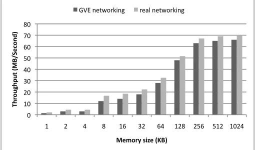
Another experiment measures the communication overhead between virtual machines. The GVE does not provide virtual network solutions. The virtual machine that is managed by GVE uses native virtual network solutions provided by Xen server or VMware ESX server. Normally a virtual machine uses a virtual network interface and is assigned with an IP address. We run a MPI ping-pong program between virtual machines to test the network performance. To make a compar-ison, MPI ping-pong program is executed on real machines. The VMM used in this experiment is VMware ESX server 3.5. In Figure 5, we can see that the throughputs between virtual machines can reach around 90% of those between real machines when message sizes are big enough.
!" #!" $!" %!" &!" '!" (!" )!" *!"
#" $" &" *" #(" %$" (&" #$*" $'(" '#$" #!$&"
!"#
$%&"'%()*+,-./0
$123)
+/4$#5)678/)*9,3) +,-"./012345.6" 3/78"./012345.6"
[image:7.612.312.567.554.704.2]VIII. PERFORMANCEEVALUATION WITHCMS
BENCHMARK
This section discusses virtual machine performance by using a high energy physics benchmark – the CMS benchmark. This test shows the performance of a compute intensive application in distributed virtual machines.
A. CMS computing software
The Worldwide LHC Computing Grid (WLCG) is a global collaboration which involves more than 140 computing centres in 33 countries in the world. The WLCG project is to build and maintain a high performance computing infrastructure for the high energy physics experiments of the Large Hadron Collider (LHC) at CERN. The CMS is one the biggest high energy physics experiments in LHC. It uses a general-purpose detector to investigate a wide range of physics, which includes the search for the Higgs boson, extra dimensions, and particles that can make up dark matter.
CMS software contains CMKIN, OSCAR, ORCA, Pythia and ROOT modules. The CMKIN [23] software package provides a common interface between physics event generators and CMS detector simulation. It offers a standard way to interface kinematics generators with CMS detector simulation. OSCAR [17] simulates for CMS analysis and reconstruction. OSCAR creates SimHits which represents the information and finally stores RawParticles, SimTracks, SimVertices and
SimHits in POOL data files. ORCA [22] is a framework for
reconstruction and is intended to be used for final detector optimizations, trigger studies or global detector performance evaluation. ORCA-digitization simulates the response of the readout electronics, which are the events simulated with OS-CAR. CMS events are digitized and reconstructed with the cor-responding ORCA applications:writeAllDigisandwriteDST.
To make full performance evaluation of virtual machines, this paper also includes several ROOT [24] based tests and the Monte Carlo generator Pythia [24] in the benchmark.
B. Test organization
The CMS benchmark test are executed in the testbed discussed at SectionVII-A. CMS benchmark is executed on virtual machines with 64-Bit processors, which support both 32-Bit and 64-Bit operating system. CMS benchmark is a legacy application that demands various software libraries. Therefore, we are interested in migrating pre-compiled 32-Bit CMS benchmark to 32-32-Bit and 64-32-Bit operating systems. The test is organized in the following modes [38], [39]:
• Legacy mode
The 64-Bit architecture is installed with 32-Bit operating system and 32-Bit application runs in the 32-Bit operating system.
• Compatibility mode
The 64-Bit architecture is installed with 64-Bit operating system and 32-Bit application runs in the 64-Bit operating system.
• Full 64-Bit mode
The 64-Bit architecture is installed with 64-Bit operating
system. Legacy applications are recompiled with 64-Bit libraries and run on the 64-Bit systems.
In the test, we run CMS benchmarks in legacy mode, compat-ibility mode and full 64-Bit mode to evaluate the performance of distributed virtual machines. Table I shows the available operational modes for CMS tasks in the test.
TABLE I
OPERATIONAL MODE FORCMS OOBENCHMARK
CMS Legacy Compatibility Full 64-Bit benchmark mode mode mode
OSCAR Yes Yes No
ORCA-digi Yes Yes No
ORCA-dst Yes Yes No
Root Yes Yes Yes
Pythia Yes Yes Yes
C. Test results
Table II and Table III show the performance of CMS benchmark in terms of Event/Second. In Table II , only one copy of CMS benchmark runs on the virtual machines. In Table III, two copies of CMS benchmarks run simultaneously. Average values of the test results are obtained from two copies. The reason of simultaneous running of two copies is to make full use of dual cores of AMD opteron 250. Each test is executed 15 times.
TABLE II
CMS OOBENCHMARK ON VIRTUALAMDOPTERON250
Legacy mode Compatibility mode
OSCAR 0.0880 0.0897
ORCA-Digi 0.135 0.119
ORCA-Dst 0.974 0.931
TABLE III
CMS OOBENCHMARK ON VIRTUALAMDOPTERON250 (2COPIES)
Legacy mode Compatibility mode
OSCAR 0.0892 0.0911
ORCA-Digi 0.137 0.118
ORCA-Dst 0.984 0.934
Table IV shows test results of the ROOT benchmark. We get the test results from one copy ROOT benchmark and average values of two simultaneously running copies. The test results are in term of ROOT marks.
TABLE IV
ROOTBENCHMARK ON VIRTUALAMDOPTERON250
Legacy Compatibility Full 64-bit
mode mode mode
1 copy 945.0 864.2 1227.4
2 copies (av.) 959.8 830.1 1196.1
Table V shows the test results of the Pythia benchmark, which processes 10000 SUSY Events. Test results are obtained from one copy of Pythia benchmark and average values of two simultaneously running copies. The test results are in terms of
TABLE V
PYTHIA BENCHMARK ON VIRTUALAMDOPTERON250
Legacy Compatibility Full 64-bit
mode mode mode
1 copy 105.30 103.96 121.38
2 copies (av.) 105.76 113.23 121.28
D. Performance evaluation
Performance evaluation with CMS benchmark on virtual machines is performed by comparing the test results on virtual machines (Table II – Table V) with those on real machines. Test results on real machines are reported in CMS internal reports [38], [39]. Table VI shows the results of running one copy of CMS benchmark on real AMD opteron 250.
TABLE VI
CMSBENCHMARK ONAMDOPTERON250
CMS Legacy Compatibility Full 64-bit benchmark mode mode mode
OSCAR 0.1186 0.1154 N/A
ORCA-digi 0.1562 0.1300 N/A
ORCA-DST N/A 1.039 N/A
ROOT stress 957.6 898.3 1402.6
Pythia 121.3 120.8 146.9
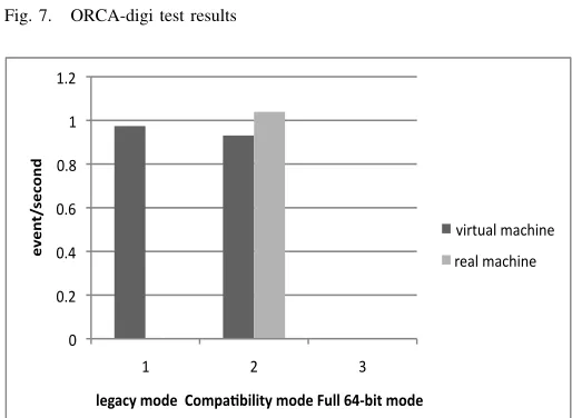
Figure 6 – Figure 10 show the comparisons of OSCAR, ORCA-digi, ORCA-dst, ROOT and Pythia test results between virtual machines and real machines. In general, virtual ma-chines can attain 70%-95% performance of real mama-chines. ROOT benchmark achieves good performance on virtual ma-chines, since ROOT stress is an I/O intensive application. The OSCAR benchmark is a computationally intensive application and it reach lower performance than the ROOT benchmark.
Comparison on different modes is also tested. It can be concluded that legacy mode and compatibility mode achieve almost the same performance. Full 64-bit mode can achieve the best performance among the three modes. It is rather obvious because in the full 64-bit mode, 64-bit applications receive access to the full physical memory range and also allowed access to the new General Purpose Registers (GPRs) as well as the expanded GPRs in 64-bit processors.
E. Discussion
IX. BUILD AVIRTUAL E-SCIENCEINFRASTRUCTURE AT
RUNTIME:ASAMPLEUSESCENARIO
This section discusses a sample use scenario of the GVE service – build a virtual e-Scientific infrastructure enabled by the GVE.
The GridSAM [25] is a standard Job Submission and Monitoring Web Service that provides a common interface to a variety of DRMs (Distributed Resource Managements), which is developed with widely accepted and standardized Web Service specifications and related technologies. ActiveBPEL engine [32] is declared as a modeling, monitoring and ex-ecution environment for scientific workflows based on the Business Process Execution Language (BPEL) [31]. A typical e-Science infrastructure [32] that involves BPEL (both the
!" !#!$" !#!%" !#!&" !#!'" !#(" !#($" !#(%"
(" $" )"
!"
!#
$%
&!'
(#)*
+!,-'.*/()!*****0(/1-23454$.*/()!****6755*89:34$*/()!*
[image:9.612.69.281.80.120.2]*+,-./0"1023+45" ,50/"1023+45"
Fig. 6. OSCAR test results
!" !#!$" !#!%" !#!&" !#!'" !#(" !#($" !#(%" !#(&" !#('"
(" $" )"
!"
!#
$%
&!'
(#)*
+!,-'.*/()!*0(/1-23454$.*/()!*6755*89:34$*/()!*
[image:9.612.309.570.171.624.2]*+,-./0"1/23+45" ,5/0"1/23+45"
Fig. 7. ORCA-digi test results
!" !#$" !#%" !#&" !#'" (" (#$"
(" $" )"
!"
!#
$%
&!'
(#)*
+!,-'.*/()!**0(/1-234+4$.*/()!*56++*78934$*/()!*
*+,-./0"1/23+45" ,5/0"1/23+45"
Fig. 8. ORCA-dst test results
BPEL script and BPEL runtime) and GridSAM [25] is as follows:
[image:9.612.310.567.435.623.2]!" #!" $!" %!" &!" '!!" '#!" '$!" '%!"
'" #" ("
!"
!#
$%
&!'
(#)*
+!,-'.*/()!**0(/1-23454$.*/()!*6755*89:34$*/()!*
[image:10.612.48.312.52.424.2])*+,-./"0.12*34" +4./"0.12*34"
Fig. 9. Pythia test results
!" #!!" $!!" %!!" &!!" '!!!" '#!!" '$!!" '%!!"
'" #" ("
!"
!#
$%
&!'
(#)*
+!,-'.*/()!*0(/1-23454$.*/()!*6755*89:34$*/()!*
)*+,-./"0.12*34" +4./"0.12*34"
Fig. 10. ROOT test results
• deploy the process onto ActiveBPEL, which is hosted in OMII Server container; from the BPEL Designer construct the request message that triggers the BPEL process;
• once got started, ActiveBPEL submits a pre-defined job in JSDL to GridSAM; GridSAM translates the JSDL script to whatever works for the underneath resource manager and sends the job to the underlying Grid computers;
• ActiveBPEL polls the job status through GridSAM’s
monitoring interface until the job is completed eventually.
A. System integration with Grid Virtualization Service
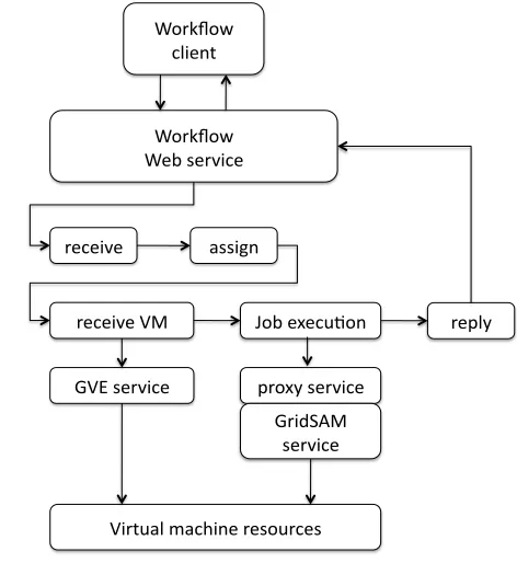
Virtual machines are employed as computing resources for workflow execution. ActiveBPEL engine dynamically in-vokes the GVE Service to request virtual machines with the GridSAM pre-installation, then organize the application in workflow and submit the workflow to virtual machines via GridSAM. The integrated workflow system includes the fol-lowing components: workflow service, proxy service and Grid-SAM service. The workflow service contains a Web service as interface, which can be invoked by workflow client. The ActiveBPEL acts as a workflow engine. It invokes Grid Vir-tualization Service to request virtual machines with GridSAM
installation, then executes workflow jobs on virtual machines via GridSAM interface. A proxy service is implemented as an interface between the ActiveBPEL engine and the GridSAM service. GridSAM job submission and monitoring services are installed in the virtual machines, via which the ActiveBPEL engine submits jobs to virtual machines.
!"#$%"&' ()*+,-'
!"#$%"&' !+.'/+#0*(+'
#+(+*0+' 1//*2,'
#+(+*0+'34' 5".'+6+(78",' #+9):'
;3<'/+#0*(+' 9#"6:'/+#0*(+' ;#*=>?4''
/+#0*(+'
[image:10.612.313.549.138.395.2]3*#-71)'@1(A*,+'#+/"7#(+/'
Fig. 11. Service composition of workflow system
B. GridSAM proxy service: proxy for ActiveBPEL to call GridSAM service
The ActiveBPEL engine cannot dynamically invoke Grid-SAM Web service due to two reasons. Firstly as virtual machines are requested dynamically, GridSAM Web services that are installed on virtual machines only can be identified at runtime. When the ActiveBPEL engine organizes a workflow, the endpoints of Web services are not yet returned because the Virtualization Service is not yet invoked by the ActiveBPEL engine. The second reason is that he GridSAM Web service is secured using WS-Security, which is unfortunately not supported by current release of ActiveBPEL engine.
A proxy service is developed in this work to overcome the above challenges. The access to the GridSAM proxy Web service is not secured using WS-security, therefore allowing non-secure interaction with ActiveBPEL. Instead of involving the GridSAM Web service directly, the Active BPEL engine invokes the GVE service and gets a set of endpoints of GridSAM Web services at runtime. It then invokes the proxy service and passes the endpoint of GridSAM Web services to be invoked as parameters. The proxy service thereafter invokes the GridSAM Web service.
C. Organize the e-Science infrastructure on demand
Service, the proxy service, and the GridSAM Web service.
!"#$%&' (!)*$'+,-.'''''-%/#%$' 01-' ,2345'6$2*#!$' 02#78(9'
:'
;' <' ='
>'
?' @' A'
B'
:C' ::' :;'
[image:11.612.56.290.87.317.2]:<'
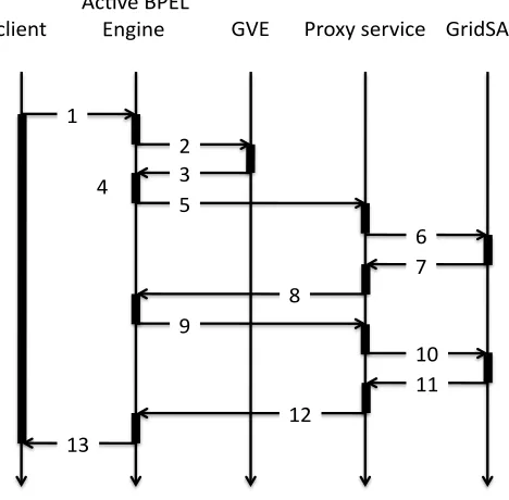
Fig. 12. The execution process of the workflow services
The execution process of these services is shown in Fig-ure 12:
1 The workflow client submits a workflow to the Ac-tiveBPEL workflow engine;
2 The ActiveBPEL workflow engine requires virtual ma-chines from the Virtualization Service;
3 The Virtualization Service returns virtual machine pro-files with GridSAM installation;
4 The ActiveBPEL engine resolves the GridSAM endpoints from the returned virtual machine profiles;
5 The ActiveBPEL engine submits workflow tasks to the proxy service with GridSAM endpoints as job parame-ters;
6 The proxy service submits tasks to GridSAM services; 7 The GridSAM service returns job status to the proxy
service;
8 The proxy service returns job status to the ActiveBPEL engine service;
9 The ActiveBPEL engine service calls the
WaitToJobCom-plete operation of the proxy service to monitor the job;
10 the proxy service calls the getJobStatus operation of GridSAM service to get the job status;
11 GridSAM service returns job status to the proxy service; 12 The proxy service returns job status to the ActiveBPEL
engine service;
13 The ActiveBPEL engine service returns results to the client when the workflow execution finishes.
X. CONCLUSION AND FUTURE WORK
In this paper we present the work of Grid Virtual Engine (GVE). GVE is a software layer which resides between users and various Virtual Machine implementations. GVE provides a standard Web service interface for users to manipulate virtual
machine resources in the wide-area distributed environment, thereafter to build a Grid computing infrastructure.
The Grid Virtualization Engine distinguishes itself from related work [1], [19], [20] in that:
• The GVE is designed and implemented in modularity. System components are wrapped with standard Web service interfaces. The modular design philosophy brings advantages such as scalability, availability and interoper-ability to the system.
• The GVE is designed and implemented in the hierarchical flavor. The higher level service, the GVE Site Service, provides a general interface, which is virtual machine technology independent. The GVE Site Service runs as a client of the GVE Agent Service. The low level service, the GVE Agent Service, handles virtual machine specific implementations. The GVE Agent Service can be plugged in the system at runtime and serve for multiple GVE Site Services simultaneously. The hierarchical design pattern makes the system more scalable to incorporate new virtual machine technologies.
This paper shows the performance evaluation and sample usage of the GVE. Test results justify the design and imple-mentation of the GVE.
The first version of GVE has been released and tested across multiple computer centers. GVE will be further developed and deployed in the large scale testbed, for example, pan-Germany D-Grid [13] testbed for various Grid applications. In detail, the future work of GVE includes, for example, development of industrial security control mechanism for the GVE, accommodation of more virtual machine technologies, e.g., Xen enterprize server and KVM, and moving the GVE work into the Cloud computing context, thus enabling to provide configurable computing platforms from productional Grid infrastructures.
REFERENCES
[1] S. Adabala, V. Chadha, P. Chawla, R. Figueiredo, J. Fortes, I. Krsul, A. Matsunaga, M. Tsugawa, J. Zhang, Mi. Zhao, L. Zhu, and X. Zhu. From virtualized resources to virtual computing Grids: the In-VIGO system. Future Generation Comp. Syst., 21(6):896–909, 2005. [2] P. Barham, B. Dragovic, K. Fraser, S. Hand, T. L. Harris, A. Ho,
R. Neugebauer, I. Pratt, and A. Warfield. Xen and the art of virtu-alization. InProceedings of the 19th ACM Symposium on Operating Systems Principles, pages 164–177, New York, U. S. A., Oct. 2003. [3] V. Buege, Y. Kemp, M. Kunze, O. Oberst, and G. Quast. Virtualizing
a batch queueing system at a university Grid center. Proceeding of Workshop on XEN in HPC Cluster and Grid Computing Environments (XHPC), LNCS, 4331:Italy, 397-406 2006.
[4] S. Childs, B. Coghlan, and J. McCandless. GridBuilder: a tool for creating virtual grid testbeds. InProceedings of 2nd IEEE Conference on eScience and Grid computing (e-Science), pages 77–77, Amsterdam, Netherlands, Dec. 2006. IEEE Computer Society.
[5] S. Childs, B. Coghlan, D. O’Callaghan, G. Quigley, and J. Walsh. A single-computer Grid gateway using virtual machines. InProceedings of the 19th International Conference on Advanced Information Networking and Applications, pages 310–315, Washington, DC, USA, 2005. IEEE Computer Society.
[6] N. Fallenbeck, H. J. Picht, M. Smith, and B. Freisleben. Xen and the art of cluster scheduling. In Proc. of 1st International Workshop on Virtualization Technology in Distributed Computing, USA, Nov. 2006. IEEE Computer Society.
[8] Java Architecture for XML Binding (JAXB) [URL]. http://java.sun.com/developer/technicalarticles/webservices/jaxb/, access on Jan. 2007.
[9] I. Foster and C. Kesselman. The Grid: blueprint for a new computing infrastructure. Morgan Kaufmann, 1998.
[10] I. Foster, C. Kesselman, and S. Tuecke. The anatomy of the Grid – enabling scalable virtual organizations. Int’l J. of Supercomp. App., 15(3):200–222, August 2001.
[11] X. Jiang and D. Xu. VIOLIN: virtual internetworking on overlay infrastructure. InProceedings of the 2nd International Symposium of Parallel and Distributed Processing and Applications, pages 937–946, 2004.
[12] K. Keahey, I. Foster, T. Freeman, and X. Zhang. Virtual workspaces: achieving quality of service and quality of life in the Grid. Scientific Programming, 13(4):265–275, 2005.
[13] Germany national Grid initiative [URL]. http://www.dgrid.de/, access on Nov. 2007.
[14] Apache Tomcat project [URL]. http://tomcat.apache.org/, access on Nov. 2008.
[15] JaX-WS project [URL]. https://jax-ws.dev.java.net/, access on Nov. 2008.
[16] LHC Computing Grid project [URL]. http://cern.ch/lhcgrid/, access on Nov. 2008.
[17] OSCAR project [URL]. http://cmsdoc.cern.ch/oscar/, access on Nov. 2008.
[18] Teragrid project [URL]. http://www.teragrid.org/, access on Nov. 2008. [19] P. Ruth, X. Jiang, D. Xu, and S. Goasguen. Virtual distributed environments in a shared infrastructure. IEEE Computer, 38(5):63–69, 2005.
[20] A. Shoykhet, J. Lange, and P. Dinda. Virtuoso: a system for virtual machine marketplaces. Technical Report NWU-CS-04-39, Northwest University, July 2004.
[21] J. Smith and R. Nair.Virtual machines: versatile platforms for systems and processes. The Morgan Kaufmann, 2003.
[22] CERN CMS Software and Computing Group. Object oriented recon-struction for CMS analysis. Technical report, CMS Internal Note, CMS-IN 1999/001, 1999.
[23] CERN CMS Software and Computing Group. CMKIN user guide. Technical report, CMS Internal Note, CMS-IN 2004/052Z, 2004. [24] CMS software [URL]. http://cms.cern.ch/software/cms/, access on Nov.
2008.
[25] GridSAM: Grid Job Submission and Monitoring Web Service [URL]. http://gridsam.sourceforge.net/, access on Nov. 2007.
[26] M. Tatezono, N. Maruyama, and S.Matsuoka. Making wide-area, multi-site MPI feasible using Xen vm. Proceeding of Workshop on XEN in HPC Cluster and Grid Computing Environments (XHPC), LNCS, 4331:387–396, 2006.
[27] Amazon Elastic Compute Cloud [URL]. http://aws.amazon.com/ec2/, access on Nov. 2008.
[28] Eucalyptus Project [URL]. http://eucalyptus.cs.ucsb.edu/, access on Sep. 2008.
[29] Glue Schema V1.3 [URL]. http://glueschema.forge.cnaf.infn.it/spec/v13/, access on Jan. 2008.
[30] Hibernate Mapping Framework [URL]. http://www.hibernate.org/, ac-cess on Nov. 2008.
[31] OASIS Web Services Business Process Ex-ecution Language [URL]. http://www.oasis-open.org/committees/tc home.php?wg abbrev=wsbpel/, access on Nov. 2008.
[32] OMII-BPEL [URL]. http://sse.cs.ucl.ac.uk/omii-bpel/, access on Nov. 2008.
[33] Open Science Grid (OSG) [URL]. http://www.opensciencegrid.org/, access on Nov. 2008.
[34] OpenNEbula Project [URL]. http://www.opennebula.org/.
[35] Unified Modeling Language [URL].
http://www.omg.org/technology/documents/formal/uml.htm, access on Nov. 2008.
[36] Globus virtual workspace interface guide [URL]. http://workspace.globus.org/vm/tp1.3/interfaces/index.html/, access on Nov. 2008.
[37] VMware virtualization technology [URL]. http://www.vmware.com. [38] H. Wenzel. Benchmarking AMD Opteron (AMD64) and Interl (EM64T)
systems. Technical report, CMS Internal Note, CMS-IN 2005/012, CMS Software and Computing Group, 2005.