International Journal of Innovative Technology and Exploring Engineering (IJITEE) ISSN: 2278-3075, Volume-8 Issue-8, June 2019
Abstract: BLDC motor is widely used because of its low maintenance and minimum losses. The objective of this paper is to develop a switching logic for speed control with regenerative braking of brushless DC motor. The supply to the BLDC motor is given from the battery through a three-phase inverter. There are two modes of operation of motor – motoring mode and regeneration mode. Using Waijung block set in MATLAB Simulink, the simulation model is built in the STM32f4 discovery board through which gating pulses for the three-phase inverter are supplied. By taking the hall sensor position as reference, gating pulses for the inverter are generated. Speed control and regenerative braking has been implemented in an electric vehicle (EV). The performance of BLDC motor in EV is analyzed by conducting the speed control at different load conditions.
Index Terms: Brushless DC motor (BLDCM), electric vehicle (EV), Regenerative Braking, STM32F4 Discovery board, Waijung block set.
I. INTRODUCTION
With the continuous increase in the number of vehicles, the local pollution has become more violent. This has spawned the EVs to gain more attention in the recent years as an alternative to conventional vehicles powered by internal combustion (IC) engines which run on non-renewable resources [1][2]. Most of the electric vehicles use BLDC motor as it is an ideal choice for the applications that require better heat dissipation, silent operation, compact form, reliability, low maintenance and high efficiency. In particular, the hub type BLDC is extensively used in most of the EVs as it reduces the hardware size and weight and inverter acts as electronic commutator. The fuel for electric vehicles is electricity which is supplied from batteries. Typical electric cars have a battery pack capability of 24 kilowatt-hour giving about 80 miles of range and Tesla Motors giving a hundred kilowatt-hour model with 335 miles of range. And it is significant that time taken for charging the battery is much longer. So, in order to increase the driving range of electric vehicles without charging the battery, the only option is to increase the size of the battery. But increasing the battery size will increase the weight of the vehicle. The best solution for this problem is to make use of
Revised Manuscript Received on June 07, 2019.
RommalaMahitha, Dept. of Electrical and electronics engineering, Amrita school of engineering, Coimbatore, Amrita viswa vidyapeetham, India.
Gowthaman B, Dept. ofElectrical and electronics engineering, Amrita school of engineering, Coimbatore, Amrita viswa vidyapeetham, India.
Mohanrajan S R, Dept. of Electrical and electronics engineering, Amrita school of engineering, Coimbatore, Amrita viswa vidyapeetham, India.
regenerative braking in BLDC motor. In conventional IC engine vehicles, during the braking process, the kinetic energy is converted into thermal energy
which is very wasteful. In regenerative braking of EVs, the energy is supplied back to the battery. During this process, it is that inertia of the vehicle that causes the motor to act as a generator to produce electrical energy to charge the battery [3]. The regenerative braking method mainly uses the back EMF in the motor during braking. The back EMF acts as a voltage source to charge the battery during regenerative braking. Usually, the battery voltage is higher than back EMF even if the EV is running at its maximum speed [4]. Therefore, an additional DC-DC converter is required to boost the voltage to required level. This increases the cost and losses of the system leading to an overall decrease in efficiency [5]. In view of the above-mentioned problem, a simple and cost-effective method is proposed to boost the back EMF. Moreover, in the practical application, the battery may get damaged due to the high surge current that is given to it during energy regeneration. Hence, a simple strategy is also proposed to restrain the current for protecting the battery during energy regeneration. To generate the PWM signals for inverter switching operation, STM32F4 discovery board is used. First step is to create a simulation model of proposed method in MATLAB. After installing WAIJUNG Module block set in MATLAB, the simulation is to be run and MATLAB automatically generates the code for generating gating signals. Hence, STM32F4 board avoids the manual coding errors and saves a lot of time as it automatically generates the code. Finally, experimental results are shown to validate the proposed method.
II. BLDC MOTOR – OPERATION AND CONTROL
A. Working of BLDC Motor
Stator of BLDC motor (BLDCM) is made up of three phase windings similar to the induction motor and the rotor is made up of permanent magnets. Back emf of this machine is trapezoidal in shape. Inverter acts as an electronic commutator wherein commutation is achieved by controlling the sequence of conduction of the inverter switches. To control the BLDC motor, it is essential to locate the position of the rotor. This can be known by employing Hall effect sensors.
Speed Control of Brushless DC Motor in Electric
Vehicle with Regenerative Braking
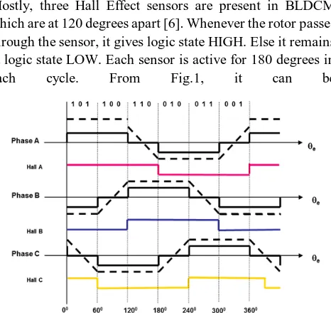
Mostly, three Hall Effect sensors are present in BLDCM which are at 120 degrees apart [6]. Whenever the rotor passes through the sensor, it gives logic state HIGH. Else it remains at logic state LOW. Each sensor is active for 180 degrees in
each cycle. From Fig.1, it can be
[image:2.595.54.287.53.273.2]Fig.1. Waveforms of phase and hall sensor signals
Fig.2. Six-step commutation process of BLDCM in a sequential manner
seen that the back EMF generated is trapezoidal in shape and the phase voltage varies in accordance with the hall sensor states. When the position of rotor is known using hall effect sensors, stator coils are energized accordingly in order to rotate the rotor. Fig. 2 shows the position of rotor and stator coils of BLDCM. The output of hall effect sensors is taken for every 60 degrees. For a complete rotation, there are totally 6 different states [6][7]. After starting, the rotation of the motor is then maintained by energizing the opposite pairs of poles in a sequential manner [1]. Two coils are energized simultaneously.
B. Normal Mode or Motoring Mode
For controlling BLDC motor, the H-Bridge inverter is commonly used [8]. To energize windings to rotate the rotor, appropriate switches need to be turned ON. During 0-60 degrees of Fig.1, phase A and phase B should be turned ON and phase C is at floating state. So, to turn ON A and B phase coils, S1 and S2 of Fig.3 should be turned ON. No two switches of same leg of inverter should turn ON simultaneously. Top switch of one leg and bottom switch of
another leg should turn ON simultaneously. Under motoring mode, all the six switches of inverter are in use. Controller takes hall sensor states as reference and generates the PWM
[image:2.595.309.545.105.307.2]Fig. 3. Circuit diagram of BLDCM
Table I. BLDCM switching sequence for motoring mode
Hall A
Hall B
Hall C
A B C S1 S2 S3 S4 S5 S6 1 0 1 +1 -1 0 1 0 0 0 0 1 1 0 0 +1 0 -1 1 1 0 0 0 0 1 1 0 0 +1 -1 0 1 1 0 0 0 0 1 0 -1 +1 0 0 0 1 1 0 0 0 1 1 -1 0 +1 0 0 0 1 1 0 0 0 1 0 -1 +1 0 0 0 0 1 1
gating pulses to turn ON appropriate switches of inverter. Table I shows the switching sequence of BLDCM for motoring mode.
C. Regenerative braking Mode
[image:2.595.53.286.300.497.2]International Journal of Innovative Technology and Exploring Engineering (IJITEE) ISSN: 2278-3075, Volume-8 Issue-8, June 2019
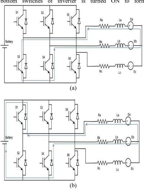
The switching logic for regenerative braking mode is same as that of motoring mode except that only the bottom switches of inverter are used during regenerative braking. At any time, top switches of the inverter are not triggered. At the time of regeneration, immediately after applying brake, one of the bottom switches of inverter is turned ON to form
(a)
[image:3.595.46.287.119.434.2](b)
Fig. 4. Illustration of current path during regenerative braking. (a) Closed loop current path to charge the
inductor. (b) Current path to charge the battery.
a closed path for the current in order to boost the inductor voltage as shown in Fig.4. (a). When the voltage in the motor becomes greater than the battery voltage, current starts flowing through the MOSFET body diodes to charge the battery as shown in Fig.4. (b).
III. EXPERIMENTAL SETUP AND RESULTS
BLDCM gets supply from the battery through the 3-phase inverter. Hall effect sensor signals from the motor are given as input to the STM32F4 discovery board which generates the gating pulses for inverter switches by taking hall sensor signals as reference. To control the speed, potentiometer is used. When the potentiometer is at its minimum position, the speed is minimum. As we move the potentiometer from minimum to maximum position, the speed varies from minimum to maximum. Fig.5 shows the schematic diagram of experimental setup of BLDCM. Fig.6 shows the hardware setup for the same and Table II shows the specifications of the BLDC motor. The simulation for generating gating pulses during motoring and regenerative braking mode is done in the matlab Simulink using WAIJUNG block set and is built in the STM32F4 discovery board which automatically generates the code for gating pulses. A switch is connected to the board to toggle from the motoring mode to regenerative
[image:3.595.308.547.178.842.2]braking mode. When the switch is OFF, PWM gating pulses for motoring mode is supplied to the inverter through a microcontroller. Also, the speed is controlled by varying the potentiometer to control the duty cycle of the PWM pulses which in turn varies the average voltage across the motor terminal varies. Whenever the switch is ON, the supply to the motor is cut off and the PWM gating pulses for regenerative braking mode is supplied to the inverter. And hence, the current flows in reverse direction and the battery is charged.
Fig. 5. Block diagram for the hardware setup
Fig. 6. Hardware set up Table II. BLDCM specifications
No of poles 4
Rated power 250 W
Rated voltage 48 V
Rated speed 250-350 rpm
Table III. BLDCM parameters observed during load test
[image:4.595.48.552.77.663.2]
Fig. 7. Efficiency plot of BLDC motor
Fig.8 Oscilloscope waveforms during motoring mode
When POT is at its maximum position implying a higher duty ratio which in turn implies at higher speed, usually the reverse current is higher. The change in current with respective to time is high for higher duty cycle of the PWM pulses. So, when regenerative braking is done at higher duty cycle, it results in a high spike of current for a short period of time which may damage the battery. This issue is resolved by using integrator in the MATLAB Simulink which gives duty ratio for PWM pulses in the form of ramp signal. Hence, at the
Fig.9 Oscilloscope waveforms during regenerative braking mode.
time of regeneration, initially duty ratio of PWM signals is low and as the time increases, the duty ratio also increases which avoids high surge currents in the battery. To analyze the performance of BLDC motor, load test is being done at different load conditions using weight gauge load set up.
INPUT
VOLTAGE
(V)
INPUT
CURRENT
(A)
S1 (KG)
S2 (KG)
(S1~S2)*0.25 (kg)
INPUT POWER (W)
OUTPUT POWER (W)
TORQUE (NM)
SPEED (RPM)
EFFICIENCY (%)
48 1.23 1.25 0 0.31 59.04 40.33 1.26 307 68.30
48 1.6 1.7 0 0.43 76.8 51.99 1.72 291 65.34
48 2 2.5 0.5 0.5 96 60.23 2.02 260 62.74
48 3 4.8 1 0.95 144 79.86 3.84 200 53.84
48 3.5 6.5 1.5 1.25 168 91.95 5.05 175 51.54
International Journal of Innovative Technology and Exploring Engineering (IJITEE) ISSN: 2278-3075, Volume-8 Issue-8, June 2019
Table III shows the values of BLDCM during load test. Fig.7. shows the plot of efficiency versus output power of BLDCM. Fig.8 shows the waveforms of source voltage, source current and source power in oscilloscope during motoring mode. Since the motor consumes power during motoring mode, the source power is positive. Fig.9 shows the amount of current and the power given back to the battery during regenerative braking operation. Since the motor acts as a generator and to charge the battery, the source power is negative during regenerative braking mode. The back EMF is boosted for some time and gets discharged for some time. For higher frequency, the magnitude of reverse current is higher. The waveform of reverse current and power during regeneration is periodic. This represents the power sent back to the battery from each winding at a time out of three windings of motor. During regenerative braking under No load condition, the current that is sent back to the battery is observed to be around 0.85A. As load increases, the amount of reverse current increases and the time taken for the discharge of energy from motor to battery decreases due to increase in the inertia of the vehicle.
IV. CONCLUSION
In this paper, the switching logic for motoring and regenerative braking mode of BLDCM has been developed using MATLAB Simulink and implemented in hardware. Laboratory experiment is done to verify the speed control and regenerative braking mode in EV. Load test has been done at different load conditions to analyze motor parameters. The amount of power used to charge the battery during regenerative mode has been observed using the oscilloscope. By charging the battery using regenerative braking, the voltage in the battery is increased which improves the driving range of the electric vehicles. Hence, the objective of increasing the driving range of the EV is achieved without increasing the battery capacity and space consumption. Finally, a simple and effective method to avoid the high surge currents that damages the battery during regenerative braking has been implemented.
REFERENCES
1. X. Nian, F. Peng, and H. Zhang, “Regenerative Braking System of Electric Vehicle Driven by Brushless DC Motor,” IEEE Transactions on Industrial Electronics, vol. 61, no. 10, pp. 5798–5808, 2014. 2. J. Srijeeth, V. C. Thiagarajan, and S. Mohanrajan, “Z-Source Dual Active
Bridge Bidirectional AC-DC Converter for Electric Vehicle Applications,” 2018 IEEE International Conference on Power Electronics, Drives and Energy Systems (PEDES), 2018.
3. R. G. Chougale and C. R. Lakade, “Regenerative braking system of electric vehicle driven by brushless DC motor using fuzzy logic,” 2017 IEEE International Conference on Power, Control, Signals and Instrumentation Engineering (ICPCSI), 2017.
4. M.-J. Yang, H.-L. Jhou, B.-Y. Ma, and K.-K. Shyu, “A Cost-Effective Method of Electric Brake With Energy Regeneration for Electric Vehicles,” IEEE Transactions on Industrial Electronics, vol. 56, no. 6, pp. 2203–2212, 2009.
5. F. Naseri, E. Farjah, and T. Ghanbari, “An Efficient Regenerative Braking System Based on Battery/Supercapacitor for Electric, Hybrid and Plug-In Hybrid Electric Vehicles with BLDC Motor,” IEEE Transactions on Vehicular Technology, pp. 1–1, 2016.
6. “Simulation Of Brushless Dc Motor Speed Control In Matlab,” International Journal of Advance Engineering and Research Development, vol. 4, no. 12, 2017.
7. M. Baszynski and S. Pirog, “A Novel Speed Measurement Method for a High-Speed BLDC Motor Based on the Signals From the Rotor Position Sensor,” IEEE Transactions on Industrial Informatics, vol. 10, no. 1, pp. 84–91, 2014.
8. Bimal K. Bose, “Power Electronics and Variable Frequency Drives Technology and Applications”, IEEE Press, ISBN 0-7803-1084-5,1997. 9. Sidharthan, V. P., P. Suyampulingam, and K. Vijith. "Brushless DC motor driven plug in electric vehicle." International Journal of Applied Engineering Research 10 (2015): 3420-3424.
AUTHORS PROFILE
Rommala Mahitha, graduate in Electrical and electronics engineering 2019 passed out from Amrita School of Engineering, Coimbatore, Amrita Vishwa Vidyapeetham, India.
Gowthaman B, graduate in Electrical and electronics engineering 2019 passed out from Amrita School of Engineering, Coimbatore, Amrita Vishwa Vidyapeetham, India.
Mail id-
Mr.S.R.Mohanrajan serves as Assistant Professor at the Department of Electrical and Electronics Engineering, Amrita School of Engineering, Coimbatore, Amrita Vishwa Vidyapeetham, India. His areas of research include Power Electronics for Renewable Energy integration and Electric Vehicles.