International Journal of Innovative Technology and Exploring Engineering (IJITEE) ISSN: 2278-3075, Volume-8 Issue-8S, June 2019
311
Published By:
Blue Eyes Intelligence Engineering & Sciences Publication
Retrieval Number: H10520688S19/19©BEIESP
Abstract: A satellite is an object that orbits around a larger object in space, such as the earth that orbits the sun and the moon that orbits the earth. We can see the location of the satellite using the satellite tracking software such as Satview and Orbitron. The main issues are most of the student only knows the position of the satellite by using a commercial satellite tracking system without learning how it is worked. The purpose of this research is to identify how to simulate the position of the satellite in its own orbits from our location at the specified time. In order to properly determine the position of any earth orbiting object, it is necessary to determine the osculating orbital elements of the selected satellite by using two line element (TLE) set provided by North American Aerospace Defense Command (NORAD). Here, the model Simplified General Perturbations (SGP) must be used to predict the most accurate the position and velocity of the satellite derived from the calculation of orbit state vectors of satellite and space debris relative to the Earth-Centered Inertial Coordinate System. This model is able to determine the most accurate satellite’s position before, after and during an epoch. To perform this methodology, an application is developed with an easy implementation using programming language C++ that able to provide the position of the satellite at high accuracy. This program will present the NORAD TLE as the input data, while the output provides the latitude, longitude and altitude also a summary of the application. Hence, this development tool will provide a better understanding and help in learning how to calculate orbit state vectors of the satellite in order to determine the position and speed of the satellite.
Index Terms: Simplified General Perturbations (SGP) Algorithm, Two Line Element (TLE), Earth-Centered Inertial Coordinate System.
I. INTRODUCTION
Nowadays, there are many satellites launched into space by developed countries that served many purposes. An artificial satellite is man-made satellite orbiting the Earth such as International Space Station, RazakSat, Cartosat-2A and so on. This satellites orbits the earth and performs the required mission depending on its application such as communication, navigation, earth observation and military. Today, there are around 250-300 communications satellites in the Clarke orbit plus 100-200 or so in lower orbits [7]. At the same time, it is also required to send information back to ground station within a specified time using electromagnetic wave for the controller to monitor its health and receive the needed data.
Revised Manuscript Received May 22, 2019.
Nooraini Hamidon, The National Space Agency of Malaysia (ANGKASA), Selangor, Malaysia
Sharizal Fadlie, The National Space Agencyof Malaysia (ANGKASA), Selangor, Malaysia
Abadi Azhar, The National Space Agencyof Malaysia (ANGKASA), Selangor, Malaysia
Did you know that Low Earth Orbit (LEO) satellite such as the International Space Station can be seen with the naked eyes? We can see it if the size of satellite is large and has a good viewing condition during tracking situation. This is because LEO is an orbit very close to the Earth with the altitude of between 160 - 1500 kilometers from the earth’s surface. LEO’s satellites circle the Earth in a period of about 90-120 minutes. These orbits are used by satellites mainly for remote sensing purpose, because being nearer to the earth, they have better resolution of the images they take, also receive the maximum reflected power from the earth owing to their proximity [8]. This research will explain the methods of how to simulate the position of the satellite in its orbits the intended location on Earth at the specified time using two line element (TLE) set format. This paper is organized as follows. In section 2, the explanation of SGP algorithms in order to determine the position of the satellite is presented. In section 3, the parameters of orbits (orbit elements) found in a TLE are described. In section 4, conversion between Earth-Centered Inertial (ECI) Coordinate System to Geographic Coordinate System also will be discussed here. In section 5 and 6, data collection method and research methodology will be described. Section 7, one computer program is developed for the tracking the satellite with an easy implementation of using programming language C++. The TLE represents the input data for the developed program, while the output data provides an accurate ECI position and velocity of the satellite. The latitude, longitude, altitude are also calculated and summary of application will be provided in section 8.
II. SIMPLIFIED GENERAL PERTURBATIONS (SGP)
In order to determine the position of a satellite, Simplified General Perturbations (SGP) models is used to calculate orbital state vector (position and velocity) and space debris relative to Earth-Centered Inertia Coordinate System. Space debris is the collection of artificial (man-made) particles in orbit about the earth which no longer serves a useful function. Such debris includes non-functional spacecraft, mission-related debris and fragmentation debris, etc [6]. SGP models are applicable for a satellite near to the Earth with an orbital period of less than 225 minutes. The most frequently used this model because it utilizes the two line elements that is frequently updated. SGP4 blockset is implemented based on the Keplerian orbit calculations but also takes a number of perturbations into account, e.g atmospheric drag and spherical harmonics [1].
Console Application to Predict Satellite
Position for Novice Learner
312
Published By:
Blue Eyes Intelligence Engineering & Sciences Publication
Retrieval Number: H10520688S19/19©BEIESP
This model can detects and handles perturbations due to the Earth’s shape, atmospheric drag, solar and lunar gravitational and radiation effects, etc
III. TWO LINE ELEMENT (TLE)
Satellite orbits are described using a set of orbital elements stored in the two line element. TLE is an important data set of a satellite produced by the North American Aerospace Defense Command (NORAD). NORAD’s Two Line Elements are used as the initialization data for the propagators [2]. TLE will provide the most accurate determination of a satellite’s position and velocity during before, after and current epoch. Epoch is a time observed for the satellite when it crosses the equator of the Earth. TLE contain three lines. Table 1 illustrates first title line is for the satellite’s name. Table 2 illustrates the second line is list of satellite information and Table 3 illustrates the third line is the classical orbital element’s info, which are standard Two-Line Orbital Element Set Format identical to that used by NORAD. For a better understanding of the NORAD two line element set format, the format description of each line is shown in Table 1 to 3 as below:
[image:2.595.47.290.342.585.2]Table. 1 Object Name
[image:2.595.310.541.503.710.2]Table. 2 Satellite Information
Table. 3 Orbital Element of Satellite
A. Orbital Elements
Orbital elements are the parameters required to identify the orbit of a specific satellite around the earth. It is also known as Keplerian elements with six parameters that are
categorized as below:
1. two of these describe the size and shape of orbits 2. three of these describe the orientation of the orbit in space
3. one of these describes the location of the satellite within the orbit.
Based on Figure 1, Semi major axis, (a) refers to one half of the major axis for the orbit that runs from center to the perimeter. The energy and period of the orbit depend only on semi major axis. Apogee defines the point in an orbit that is farthest from the Earth while the point in an orbit that is closest to the Earth is called the perigee [3]. Eccentricity, (e) describes the roundness of an orbit. It describes the shape of the ellipse. If the orbit is a perfect circle, the eccentricity is 0 and the range is from zero to less than one [3]. Eccentricity equals 1 defines that the shape of the orbit is parabolic while eccentricity more than 1 represents the shape of the orbit as hyperbolic [3].
Besides that, inclination, (i) is the angle between the equator and the orbit when looking from the center of the Earth [4]. If the orbit went exactly around the equator from left to right, the inclination would be 0 [3]. The inclination ranges from 0 to 180 degrees [3]. The ascending node is the place where the satellite cross the equator while going from the South to the North. The angle be-tween the sun and the intersection point of the equatorial plane move to North on the first day of spring is called the vernal equinox [3]. Thus, the right ascension of the ascending node, (Ω) is the angle from the center of the earth, between vernal equinox and ascending node, measured counterclockwise. Other parameters is the Argument of Perigee, (ω) measured as the angle between the ascending node and the orbit’s point of closest approach to the Earth (perigee).
The main element that defines the location of the satellite within the ellipse is the true anomaly, (v). It is the angle between the perigee point and the satellite’s location where it is measured in the direction of the satellite’s motion [5].
[image:2.595.48.282.615.732.2]International Journal of Innovative Technology and Exploring Engineering (IJITEE) ISSN: 2278-3075, Volume-8 Issue-8S, June 2019
313
Published By:
Blue Eyes Intelligence Engineering & Sciences Publication
Retrieval Number: H10520688S19/19©BEIESP
IV. ECI TO GEODETIC CONVERSION
The conversion of the Keplerian orbital element to the ECI state vectors is discussed in this section. With all orbital elements that have been presented in the previous section, the determination of the orbital state vector (position and velocity) can be calculated. Based on the ECI coordinate system, we know that the z-axis lies at a 90º angle to the equatorial plane and runs along the earth’s rotational axis pointing north. Thus, inclination refers to the angle between the angular momentum vector and the unit vector in the Z direction [2]. The y-axis completes the right-handed orthogonal system while the x-axis points in the direction of the vernal equinox. ECEF is a right-handed orthogonal system that rotates with and is attached to the earth. Every single point relative on the earth map can be specified by the calculated latitude, longitude and altitude (LLA). For this conversion, we will refer to World Geodetic Standard 1984 (WGS84) is a reference standard to convert from ECEF to geodetic datum.
V. DATA COLLECTION METHODS
In this case, we were selected the intern from the local university who is interested to undergo the training at our ground station in space centre to participated in the experiment. The students were from a related course background with space and computer such as aerospace, communication engineering and electrical engineering. In order to gather the information, they were need to answer a simple questionnaire that consists of a series of questions in order to survey their level of knowledge about the basic of satellite navigation and position. The questionnaire paper as shown in Figure 2 has three sections: A, B, C and D which is structured as follow:
section A is on personal data of the respondents section B is contains questions on basic about a satellite. It has a total of 5 items.
section C is contains questions on the orbital parameter. It has 10 items.
[image:3.595.133.436.326.628.2] section D is about two line element. It has 5 items.
Fig. 2 Sample of questionnaire paper
At the same times, we have also interviewed the student individually in one session around 30 minutes on average. We explained to each student that they need to study about any topic that related with the satellite navigation and position of the satellite in its own orbit and some questions would be asked according to this topic. Based on the result, we can concluded that the student’s knowledge about these topic is very poor in order to determine the position of the satellite.
VI. RESEARCH METHODOLOGY
314
Published By:
Blue Eyes Intelligence Engineering & Sciences Publication
[image:4.595.52.288.48.115.2]Retrieval Number: H10520688S19/19©BEIESP
Fig. 3 Process of developing application
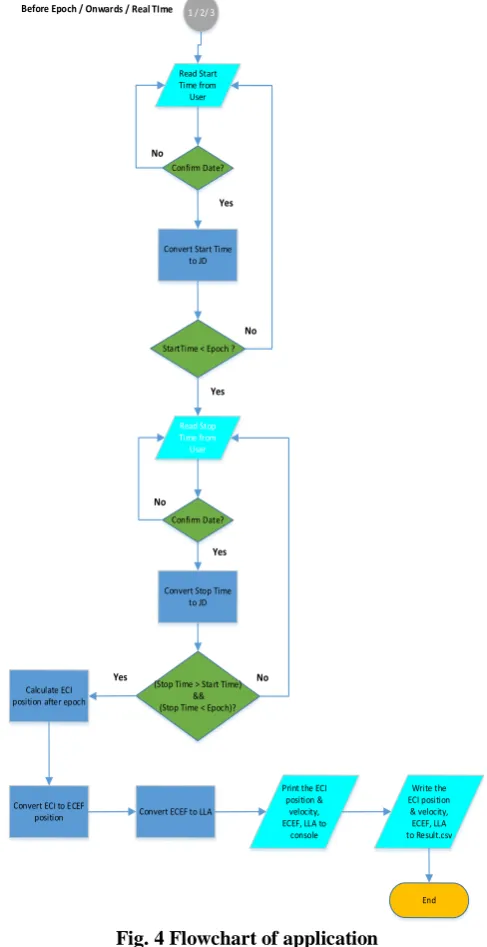
Besides that, comment is also provided in every line of the source code to explain the purpose of the code writing and to make it easier to understand the functions. Basically, the application read the TLE and requires the user to pass a time (Julian Date) for the calculation using SGP4 algorithm. The ECI position and velocity of selected satellite at the specified time are returned. The step of application are represented in a diagram as Figure 4:
Read TLE from file
Create TLE Object
Create Satellite Object
Read Choice From User (Observation
Option) Convert Epoch to
UTC
Choice = 1/2/3? Start
Display Info on Console
1 2 3
[image:4.595.303.547.56.530.2]1 / 2/ 3
Fig. 4 Flowchart of application
VII. SAMPLES OF THE CONSOLE INTERFACES
International Journal of Innovative Technology and Exploring Engineering (IJITEE) ISSN: 2278-3075, Volume-8 Issue-8S, June 2019
315
Published By:
Blue Eyes Intelligence Engineering & Sciences Publication
[image:5.595.50.290.43.465.2]Retrieval Number: H10520688S19/19©BEIESP
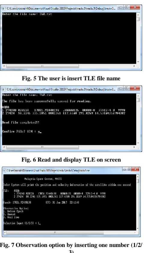
Fig. 5 The user is insert TLE file name
[image:5.595.310.542.49.187.2]Fig. 6 Read and display TLE on screen
Fig. 7 Observation option by inserting one number (1/2/ 3)
Fig. 8 Start time of the observation
Fig. 9 Stop time of observation
Fig. 10 Calculation of ECI position and the velocity of satellite, ECEF position and LLA
VIII. RESULT / OUTPUT
In this development, the objective of the system is to print the position and velocity of the Aqua satellite at before epoch observation. The system is very straightforward to select TLE files and time observations. As the result, system will generate two types of files as an output shown in Figure 11 and Figure 12. Firstly, CSV file is to write the calculated ECI position (km) and velocity (km/s) with X, Y, Z axis in the earth orbit. Here, conversion ECI to ECEF coordinates also has been calculated to identify the latitude, longitude and altitude (ground tracks) of Aqua satellite within the selected time. Second, the txt files also has been provided to summary of the program and related library usage, numbers representing the orbital elements based on the selected TLE. Here is sample output of the application:
[image:5.595.272.543.423.833.2]316
Published By:
Blue Eyes Intelligence Engineering & Sciences Publication
[image:6.595.48.292.49.250.2]Retrieval Number: H10520688S19/19©BEIESP Fig. 12 Summary file
IX. CONCLUSION
This research papers focus on the application to simulate the position of the satellite in its own orbits at the specified time has been presented. The focus user of this application is the novice learner, especially the intern from the local university who is interested to undergo the training at the Space System Development & Operational Division, National Space Agency of Malaysia (ANGKASA) at Banting, Selangor. The outcome from this problem solving is the student are able to implement high-quality assessment practices after understanding the theory behind it by using this application. Hence, the development of these applications is looking at one of the very good efforts to produce the graduates who are highly knowledgeable in the theoretical as well as practical aspects of satellite and space field. Finally, we hope this form of application will motivate similar efforts for analytical theories in a similar fashion, along with the satellite data to use with each theory.
ACKNOWLEDGMENT
I take this opportunity to express my profound gratitude and respect to various people who gave me incredible support in terms of resources and knowledge sharing to complete my research works smoothly over the past six months. Firstly, I would like to show my sincere appreciation to Director of Operational and Space System Division, Sir Maszlan Ismail whose encourage me to start work, persevere with it and successfully developing the application as the outcome needed for the study. Secondly, I am highly indebted to my colleagues, especially Sharizal Sabri who gave me the direction, assistance, encouragement, guidance and support from the initial to the final stage, which enabled me to complete this small study in time. I also would like to give special thanks to all my friends especially to Dr. Abadi Azhar, who has given some idea and sharing knowledge to me in order to publish this paper.
REFERENCES
1. Amini, R., Larsen, J. A., Izadi-Zamanabadi, R., & Bhanderi, D. D. (2005, October). Design and implementation of a space environment simulation toolbox for small satellites. In 56th International Astronautical Congress (Vol. 9, pp. 6207-6213).
2. Larson, W. J., & Wertz, J. R. (1992). Space mission analysis and design (No. DOE/NE/32145--T1). Microcosm, Inc., Torrance, CA (US).
3. Michel Capderou (2014). Handbook of Satellite Orbits from Kepler to GPS (Vol. 10). Springer Science & Business Media.
4. Dusan Vuckovic, PetarRajkovic, DraganJankovic and Olivera Pavic (2010). Guidelines for Satellite Tracking. Faculty of Electronic Engineering, University of Nis, Serbia
5. Analytical Graphics, Inc. (AGI). (2010). Educational Resources. 6. Space Waste Solutions (2015). Space Debris
http://www.spacewastesolutions.com/space-debris-2/
7. Mark R. Chartrand (2004), Satellite Communications for the Nonspecialist. A Publication of SPIE-The International Society for Optical Engineering, Bellingham, Washington USA.