University of Southern Queensland
Faculty of Engineering and Surveying
The Autonomous Unmanned Aerial Surveillance
Vehicle
Navigation and User Interface
A dissertation submitted by
Soz Deja Knox
in fulfilment of the requirements of
Courses ENG4111 and ENG4112 Research Project
towards the degree of
Bachelor of Engineering (Electrical and Electronic)
Abstract
There has been a steep growth, throughout the World, in civilian UAV applications. UAVs offer cost effective alternatives for many applications, as they enable objectives be carried out without the risk to pilots. In terms of crop surveillance, they offer a cheap alternative to satellite and manned aerial imagery. These current techniques are limited due to cloud cover, and poor image capture resolution. By flying a UAV at low altitudes, these limitations may be greatly reduced. With the recent financial commitment from the Queensland State Government, to the funding of a UAV research and development facility, the future of UAV technology and its potential market is being recognized. Current UAV navigation and guidance packages on the market are prohibitively expensive. This paper describes the design and implementation of a cheap navigation and user interface for the specific purpose of carrying out surveillance over a pre-determined flight path in a UAV. The system has been designed assuming a suitable automatic flight control system is available, for receipt of the guidance outputs.
The prototype system described in this dissertation successfully carries out navigation, guidance and surveillance over a pre-determined flight path. Simulated testing using a trolley guided by hand, communicating wirelessly to a ground control station with user interface, has proven the successful design, implementation and final integration of the individual elements.
UNIVERSITY OF SOUTHERN QUEENSLAND
Faculty of Engineering and Surveying
ENG4111/2
Research Project
Limitations of Use
The Council of the University of Southern Queensland, its Faculty of Engineering and Surveying, and the staff of the University of Southern Queensland, do not accept any responsibility for the truth, accuracy or completeness of material contained within or associated with this dissertation.
Persons using all or any part of this material do so at their own risk, and not at the risk of the Council of the University of Southern Queensland, its Faculty of Engineering and Surveying or the staff of the University of Southern Queensland.
This dissertation reports an educational exercise and has no purpose or validity beyond this exercise. The sole purpose of the course pair entitled “Research Project” is to contribute to the overall education within the student’s chosen degree program. This document, the associated hardware, software, drawings, and other material set out in the associated appendices should not be used for any other purpose: if they are so used, it is entirely at the risk of the user.
Prof G Baker Dean
DISCLAIMER PAGE
Certification
I certify that the ideas, designs and experimental work, results, analyses and conclusions set out in this dissertation are entirely my own effort, except where otherwise indicated and acknowledged.
I further certify that the work is original and has not been previously submitted for assessment in any other course or institution, except where specifically stated.
Soz Deja Knox
Student Number: 0039911442
Acknowledgements
I would like to thank the following people and organisations who have made completion of this project possible.
• My supervisors, Mark Phythian and LEUT Kathryn Burr who managed to answer my questions or point me in the right direction over and over again throughout the year,
• Terry Byrne for his technical expertise, enthusiasm and for the excellent idea in the first place,
• The Royal Australian Navy who sponsored me financially in the past three years. I would not have been able to focus so much of my energy into this project, thereby gaining as much as I have through this process, without the freedom provided me.
• Craig Littleton, Dean Thompson and Michael Costa for putting up with me everyday, and
• My two beautiful dogs- Rooster and Dex.
Soz Knox
Table of Contents
Abstract ii
Certification v
Acknowledgements vi
Table of Contents vii
Chapter 1 Introduction 17
1.1 History of UAV Development 18
1.2 Project Background 19
1.3 Project Aim 20
1.3.1 Operational Requirements 20
1.3.2 Performance Requirements 20
1.3.3 Constraints 21
1.4 Project Objectives 21
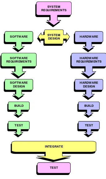
1.5 Project Methodology 22
1.6 Aspects of Ethical Responsibility 25
1.7 Dissertation Structure 25
Chapter 2 Navigation and guidance 28
2.2 Compass 31
2.3 Navigation Strategy 32
Chapter 3 Image Capture and User Interface 34
3.1 Image Capture 34
3.2 User Interface and Communications 36
Chapter 4 System Architecture 38
4.1 Original Concept 38
4.2 Resource Analysis 40
Chapter 5 Risk Assessment 43
5.1 Identifying Risks 44
5.2 Evaluating Risks 45
5.3 Risk Control 46
Chapter 6 Navigation System Hardware Design and Implementation 49
6.1 Flight Computer 49
6.1.1 SPI 52
6.1.2 SCI 54
6.1.3 CAN 56
6.2 Development Tools 57
6.2.1 TwinPEEKs Monitor Program 58
6.2.2 ImageCraft ICC12 V6 59
6.3 Sensors 59
6.3.1 GPS 60
6.3.1.1 GPS Testing 62
6.3.2 Compass 62
6.3.2.2 Compass Testing 66 6.3.2.3 Mitigation of Incorrect Heading Provision Risk 66
Chapter 7 Image Capture and User Interface Implementation 68
7.1 Ground Control Station 68
7.1.1 Data link 69
7.1.1.1 Transceiver Testing 70
7.2 Image Capture System 71
7.2.1 Image Capture System Test 71
7.3 Hardware Integration 72
Chapter 8 Software Design and Implementation 73
8.1 Navigation Algorithm 73
8.2 GPS Message Holder 75
8.3 Compass Interface 75
8.4 Camera Trigger Module 77
8.5 User Interface (GUI) 77
8.5.1 GUI Behaviour 81
8.6 Inter-Processor Communications 82
8.7 Validation and Testing 83
8.7.1 Navigation 83
8.7.2 User Interface 84
Chapter 9 System Validation and Testing 85
9.1 First System Test Method 85
9.2 Results 87
9.3 Discussion 88
9.4 Second System Test Method 89
9.5 Results 91
Chapter 10 System Performance Discussion 93
Chapter 11 Conclusions and Recommendations 95
11.1 Overall Performance 95
11.2 Recommendations for Further Work 97
References 99
Appendix A- Project Specification 102
Appendix B- 68HC(9)12D60 Block Diagram 104
Appendix C- Card12 Schematic 106
Appendix D- NMEA Transmitted Sentences GPS 35LP 107
Appendix E- GPS Communications Assembly Language Program 113
Appendix F- Raw Captured GPS Data 117
Appendix G- HC12 Source Code 119
G.1 navigationalgorithm.c 121
G.2 hc12.h 127
G.3 GPSMessageHolder.h 130
G.4 GPSMessageHolder.c 131
G.5 compass.h 134
G.6 compass.c 135
G.8 can.c 138
Appendix H- User Interface Source Code 139
H.1 Main.java 141
H.2 GCSFrame.java 142
H.3 WaypointPanel.java 144
H.4 SerialConnection.java 148
H.5 SerialParameters.java 153
H.6 SerialConnectionException.java 159
H.7 UAVStatusPanel.java 160
H.8 TelemetryPane.java 162
H.9 SevenSegment.java 166
List of Figures
Figure 1- System Development Methodology 24
Figure 2- UAV heading and bearing 32
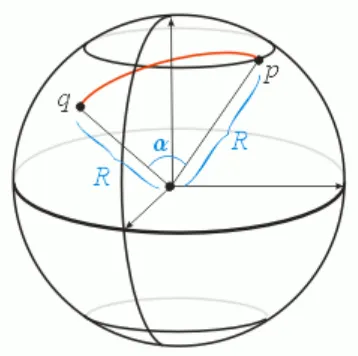
Figure 3- Great Circle Distance 33
Figure 4- System Block Diagram 39
Figure 5- Risk Management Process Overview 44
Figure 6- Card 12 50
Figure 7- HC12 Port S 51
Figure 8- DDRA and PORTA 51
Figure 9- HC12 SPI configuration 52
Figure 10- Typical GPS 35-HVS Application Architecture 61
Figure 11- Vector 2x Compass Module 63
Figure 12- V2X Compass Board Layout 64
Figure 13- Data Clock Timing Diagram 65
Figure 14- 9XStream 900 MHz Wireless Module 70
Figure 15- Integrated Hardware Wiring Diagram 72
Figure 16- Navigation System Flow Diagram 74
Figure 17- GCS GUI Logic Scenario Diagram 79
Figure 18- Ground Control Station User Interface 81
Figure 19- First System Test Trolley and Components side view 86
Figure 20- First System Test Trolley front view 86
Figure 21- System Test Path 1 87
Figure 22- Navigation Circuit 90
Figure 23- Navigation System (in protective housing) 90
Figure 24- Second System Test Ground Control Station 91
Figure 25- System Test Path 2 91
List of Tables and Equations
Table 1- Hardware Resources Used 40
Table 2- Software Resource Used 41
Table 3- GW/SLOWSTICK aircraft 41
Table 4- Likelihood Rating Criteria 45
Table 5- Consequence Rating Criteria 45
Table 6- Risk Level Matrix 46
Table 7- Risk Assessment 47
Table 8- HC12 SPI registers 53
Table 9- SPI clock rate selection 54
Table 10- Baud Rate Generation 55
Table 11- 68HC(9)12D60 Memory Map 58
Table 12- V2X Compass Pin Connections 64
Equation 1- Great Circle Distance Formula 33
Equation 2- Bearing 33
Equation 3- Baud Rate Calculation 55
Equation 4- Heading Error Scaling 76
Nomenclature
ABR Australian Book of Reference ABS Acrylonitrile Butadiene Styrene A/D Analogue to digital
Algorithm Step by step procedure for solving a problem
ANSI C American National Standards Institute for C programming language ASCII American Standard Code for Information Interchange
Assembler Translator from assembly language to machine language AS/NZS Australian New Zealand Standard
Autonomous Self governing; self controlling; self contained Avionics Aviation electronics
Baud rate The rate at which data flows BCD Binary Coded Decimal
Binary Number system consisting of zeros and ones only Bit Binary Digit- smallest unit of storage in a computer Byte A group of eight data bits
C Standardised programming language CAN Controller Area Network
CASA Civil Aviation Safety Authority CASR Civil Aviation Safety Regulations
Compiler Translates a high level language into machine language
CR Carriage Return
C++ An extension of the C programming language (object oriented) DDR Data Direction Register
DGPS Differential Global Positioning System DME Distance Measurement Equipment
Flash Non-volatile memory
ft Foot
GCS Ground Control Station
GIS Geographical Information System
GND Ground potential
GPS Global Positioning System GUI Graphical User Interface
ha Hectare
HC12 16 bit microprocessor
Hz Hertz
IBM International Business Machines Corporation
ICC12 ImageCraft Integrated Development Environment (Compiler) IDE Integrated Development Environment
IEEE Institute of Electrical and Electronic Engineers Java Object oriented programming language
KB Kilo Byte
LAN Local Area Network
LF Line Feed
LORAN Long Range Navigation system LSBF Least Significant Bit First Mbits/s Mega bits per second
MHz Mega Hertz
MISO Master In Slave Out MOSI Master Out Slave In
NASA National Aeronautics and Space Administration NDB Non-directional beacon
NMEA- 0183 National Maritime Electronic Association standard OEM Original Equipment Manufacturer
Payload Instruments or equipment carried by an aircraft PC Personal Computer (usually IBM compatible) Pseudorange Distance measurement based on correlation
RAM Random Access Memory
RF Radio Frequency
RMC Recommended Minimum Sentence (GPS) RPV Remote Piloted Vehicle
RTS/CTS Request to send/ clear to send
SCI Asynchronous Serial Communications Interface SCLK Clock signal
Servo Electro-mechanical device that moves control surfaces SLAM Simultaneous Localisation and Mapping
SPI Serial Peripheral Interface Telemetry Data stream of measured values UAV Unmanned Aerial Vehicle
USQ University of Southern Queensland UTC Universal Time Coordinated VDC Direct Current Voltage
Vin Input Voltage
VOR VHF omnidirectional range
V2X Compass Module
Waypoint A specific location defined by GPS coordinates xxxBR Baud Rate Register
$GPGGA Global Positioning System fixed data sentence 1
λ Longitude of initial position 2
λ Longitude of desired position 1
Φ Latitude of initial position 2
Chapter 1
Introduction
An Unmanned Aerial Vehicle (UAV) is a powered aerial vehicle sustained in flight by aerodynamic lift and guided without an onboard crew. It may be expendable or recoverable and can fly autonomously or be piloted remotely.
Autonomous UAVs require systems that enable them to maintain a stable attitude and the ability to follow desired trajectories. These avionic systems require continuous gathering of data from sensors (and human inputs), and the ability to process this information to guide and control the UAV through the generation of actuator commands. The avionics package necessary to carry out these functions includes a processor, sensors, software and data link hardware (Dittrich 2002).
Navigation and guidance of a UAV over a pre-determined path assumes that the existing system is capable of carrying out autonomous straight and level flight. The existing avionics package is then supplemented with extra sensors and software to include navigation and guidance capability.
1.1
History of UAV Development
Unmanned Aerial Vehicles have been around since the dawn of aviation, and Australia has been developing some form of UAV since the late 1940s including the highly successful GAF Jindivik target drone (Wong & Bil 2003). Remotely Piloted Vehicles (RPVs) have been used in niche military applications, and whilst many believed they would take over various roles of piloted aircraft, the fact that they require a skilled pilot on the ground has limited their growth (Wong & Bil 2003). Current UAV technology however, allows for fully autonomous systems to be employed. It has been the development of lightweight, inexpensive and compact sensors and microprocessors as well as a fast growing world-wide UAV knowledge base to which Wong and Bil (2003) attribute the steep growth in the market for civilian UAV applications. UAVs have unmatched qualities that often make them cost effective methods of carrying out objectives that may be either highly risky to pilots or where their presence isn’t necessary.
Recently, the Queensland State Government committed financial assistance to aid in a UAV research and development facility in Brisbane. As stated by Premier Beattie (Dept. of State Development, Trade and Innovation. 2005):
“UAVs comprise a significant aerospace research and development opportunity that is not being pursued by any other State.”
This commitment from the State Government proves the relevance and value of the project represented by this dissertation, and endorses the University of Southern Queensland’s promotion of UAV development as an ongoing project.
• UAV certification is not required for those weighing less than 150kg and flying below 400ft (approx. 1312 m). This is considered a ‘small’ UAV.
• If flying outside these parameters then certification is required and continuous communications are necessary.
The CASA regulation does not specify a certification process. In fact, there is presently no guidance on how to carry out certification in spite of its requirement under the conditions listed above.
‘Small’ UAVs have no restrictions imposed upon their operation. The operator of the UAV is responsible for ensuring that the UAV is operated safely and remains clear of potential low level traffic, structures, powerlines etc (CASA 1998).
1.2
Project Background
The Autonomous Unmanned Aerial Surveillance Vehicle – Navigation and User Interface is a follow-on project initiated by Michelle Keefe (2003). The primary requirement for this project was to develop a functional prototype of an autonomous radio-controlled aircraft for the purpose of conducting aerial surveillance over a pre-determined path. This project was carried out up to the point of semi-autonomous flight (straight and level), remote direction controlled by the user.
1.3
Project Aim
The aim of this project was to develop a navigation algorithm, image capture system and user interface to integrate into a fully functional prototype of an autonomous Unmanned Aerial Vehicle (UAV) capable of carrying out surveillance over a pre-determined flight path.
1.3.1
Operational Requirements
The overall requirements of the system were as follows:
• The system shall provide a user interface to allow entering of waypoints to determine a flight path.
• The system shall provide navigational guidance information to allow autonomous flight over this pre-determined flight path.
• The system shall allow capturing of image information over pre-determined points on the flight path.
• The system shall be integrated into a fully functional prototype UAV.
1.3.2
Performance Requirements
For the purpose of this project, certain assumptions were made regarding the scope of the UAV’s performance. These assumptions were:
• The aircraft will be remotely controlled by a user during take-off and landing.
• The UAV will not be flown over 400ft (1312m) and will not weigh more than 150kg.
• The camera chosen for surveillance will be limited to a finitenumber of pictures based on its current memory capability and resolution.
The flight path chosen includes no more than four waypoints as a means of ensuring that the distance from the GCS mentioned above is not exceeded.
1.3.3
Constraints
As this was a University of Southern Queensland Faculty-sponsored project, resources and costs associated are limited by those available to the faculty. As such, every effort was made during the system design phase to utilise available hardware and software. Where possible, the off the shelf solutions chosen, balance low cost with acceptable quality.
The payload limitation of the remote controlled aircraft chosen for this project represented the primary design and performance constraint. The model aircraft to be used originally did not have a very large payload capability. The cost of these aircraft is proportional to the payload capabilities. As a consequence, all hardware for the project was chosen to be as small and light as possible to achieve acceptable levels of performance.
1.4
Project Objectives
The objectives of this project in accordance with the specification, as included in Appendix A, were as follows:
2. Research requirements for the design and implementation of an image capture system including hardware, interfacing requirements and payload limitations.
3. Research communication alternatives to interface Ground Station (user interface) with UAV for uplink of navigation algorithm and downlink of UAV telemetry.
4. Design, develop and test individual systems, i.e. navigation algorithm, image capture system and user interface.
5. Design interface for the individual systems and integrate to enable surveillance over a pre-determined path with non time entering of flight path and real-time telemetry downlink.
6. Construct prototype UAV (using a model aircraft) and integrate systems with ‘Autonomous Control and Flight Dynamics’ project being carried out by Craig Littleton.
1.5
Project Methodology
Once analysis of the UAV system level requirements was performed, hardware selection for the UAV was carried out. Hardware selection in a UAV environment requires that the sensors, microprocessor and data link hardware be chosen with the specific operational requirements in mind. The selection of this hardware and its integration into the final system is discussed in Chapters 6 and 7.
Similarly, once the UAV system requirements were allocated to the software sub-system, design and development of both a navigation algorithm and user interface were carried out. Sensor data was integrated into the navigation solution through the use of algorithms implemented in software and programmed into the navigation UAV microprocessor. The implementation of the navigation algorithm as well as the development of the Ground Control Station and user interface is discussed in Chapter 8.
SYSTEM DESIGN
INTEGRATE SYSTEM REQUIREMENTS
TEST
HARDWARE
HARDWARE REQUIREMENTS
HARDWARE DESIGN
BUILD
TEST TEST
BUILD SOFTWARE
DESIGN SOFTWARE REQUIREMENTS
[image:24.595.152.494.92.667.2]SOFTWARE
1.6
Aspects of Ethical Responsibility
The development of a cheap, fully autonomous UAV capable of carrying out surveillance over a pre-determined flight path may offer an affordable and sustainable alternative to current means of crop surveillance. If used, it will alleviate the safety issues inherent in human-flown aircraft used for this purpose. It is a technical task that has the potential to endanger the public if the technology is used for the wrong purposes. The ease and low cost may allow the technology to be used by those with less innocuous objectives. The UAV has the potential to be used as an autonomous weapon or for intrusive surveillance. Also, by its nature, the UAV is an aircraft operating in domestic airspace and as such, there exists a legal responsibility to ensure it is operated safely and effectively within that airspace.
The performance requirements for this project do not exceed the height or weight restrictions imposed on UAVs by the CASA 1998 regulation, and as such, operation of the UAV will not require certification. This does not mean that the prototype UAV will not be capable of flying at those altitudes and as such, it is important that the prototype UAV be considered potentially dangerous and only be operated by engineering staff/ students under strict supervision and in a safe environment.
The prototype UAV is not a toy and should not be treated as such. Any possible future marketing of the product to the government or to farmers would need to include thorough warnings associated with the above-mentioned concerns and educational materials outlining regulatory issues as well as detailed instructions on its use.
1.7
Dissertation Structure
This dissertation is organised as follows:
Chapter 3 includes the literature review carried out on the image capture system and user interface. It discusses the efficacy of using UAVs for crop surveillance, and some of the methods available to implement an image capture system. The purpose and function of the user interface is discussed, along with the benefits of the chosen Programming language. The Ground Control Station hardware requirements necessary to implement the user interface is described.
Chapter 4 gives a description of the system architecture design concept as decided upon, based on the literature review carried out. The chapter also presents a resource analysis carried out based on the conceptual design.
Chapter 5 is a risk assessment carried out on the project and its activities. An evaluation of these risks and the necessary control measures is tabulated.
Chapter 6 describes in detail the navigation and guidance system hardware used, and how it was developed. The development tools used to aid in the implementation of the hardware are described, and individual testing of the components is discussed.
Chapter 7 explains the selection and implementation of the image capture and user interface hardware used in this project. Testing of each of these components is discussed, and an integrated system hardware wiring diagram is provided.
Chapter 8 describes the system software design and implementation carried out. The chapter documents each of the programs necessary to carry out the navigation algorithm and hardware interfacing. The user interface design is described and final implementation shown. Testing of the individual functions is discussed.
Chapter 9 outlines the integrated system test methods, results and discussion necessary for system verification. Where required, options for problem rectification are canvassed, and subsequently implemented.
Chapter 2
Navigation and guidance
Navigation is the determination of the position and velocity of a moving vehicle (Kayton & Fried 1997). Guidance refers to the act of steering toward a destination of known position from the aircraft’s present position. Therefore, navigation is a necessary step towards aircraft guidance. Navigation systems can be categorised as either positioning or dead-reckoning where positioning systems measure the state vector (the three components of position and the three components of velocity make up a six-component state vector) without regard to the path travelled by the aircraft in the past. Dead-reckoning navigation systems derive their state vector from a continuous series of measurements relative to an initial position. The guidance loop for any UAV is required to generate guidance commands from the UAV states and the desired waypoint information. These commands are passed to the flight control loop which is then responsible for controlling the actuators and servos of the UAV control surfaces.
students developed a UAV package for use in local research activities. The development saw a modern cost-saving approach to developing a UAV and its subsystems. Their budget, however, was US $15 000. According to the Department of Defence (2005), the Avatar UAV and ground station cost US $40 000. The Cornell University packge, whilst a vast improvement on the previous cost of UAVs, still represents a large investment. They use a GPS receiver and pressure sensors to detect position and velocity state, and an autopilot system capable of flying a series of GPS coordinates. Their autopilot includes a powerful onboard computer running Windows XP. This, in addition to the sensor and communication hardware, represents a large payload and as a consequence, the use of a large heavily modified remote controlled aircraft.
Clearly, there is a lack of low cost navigational and guidance packages on the market that can be integrated into small scale aircraft such as UAVs.
2.1
GPS
The fully operational GPS satellite constellation comprises 24 satellites as described in the American Federal Radio Navigation Plan (1996). GPS receivers use ranging code from at least four GPS satellites to calculate their instantaneous position and velocity. Most GPS receivers output their data in NMEA- 0183 format. This format includes a variety of transmitted sentences/ messages that provide data for navigational purposes. These sentences are transmitted in ASCII code, each beginning with a dollar sign ($) and ending with a carriage return and linefeed (<CR><LF>). Data is comma delimited. The sentence extracted for use depends on the required application with the recommended minimum sentence being the RMC message (Stefan 2000). The RMC message provides the following information:
• Universal Time Coordinated (UTC),
• GPS status (indicating whether the incoming GPS data is valid),
• Latitude, Northern or Southern hemisphere,
• Longitude, East or West indicator,
• Speed (From 0000.0 to 1851.8 knots),
• Course over ground (000.0 to 259.9 degrees),
• Date, and
• Magnetic Variation (000.0 to 180 degrees).
The following is an example of a GPS transmitted RMC message:
$GPRMC,1030804.374,A,0411.8650,N,10326.3480,E,0.00,3.85,010304,,*03
and smooths the data from the available sensors to correct for their inherent errors (Merminod 1989). Kalman Filtering techniques are used by military aircraft (Royal Australian Navy S-70B-2 helicopters) to ensure accurate position information over long distances. These systems are useful for long range flying, but are not considered necessary for short flights where errors in the inertial sensors and low frequency updating of GPS are not considered critical. Unfortunately, whilst GPS can provide long term stability and accuracy, its reliability is not guaranteed as it relies on a clear line of sight from the receiver to at least four satellites to guarantee a position fix. This is another reason why many UAV applications see the use of GPS complementing inertial navigation systems; ensuring availability of position information regardless of the weather or environmental conditions. When designing UAVs with high manoeuvrability which may impede the GPS receiver to satellite signals, it is possible to add a second redundant GPS receiver to ensure that position information is possible regardless of whether the UAV is upright or not.
2.2
Compass
When using GPS to provide heading information, there is a necessity for an extra sensor to provide attitude information. The GPS provides heading information but only at a 1Hz rate. A faster update rate can be found using a compass, which can be used to supplement the GPS with a higher heading sampling rate.
A popular compass on the market is the HMR3000 Digital Compass Module. This compass provides heading, pitch and roll for use in navigation and guidance systems and is recommended for use in unmanned vehicles (Honeywell Sensor Products n.d.). The HMR3000 costs $675 and therefore, was not considered a viable option for this project.
host device .This is compatible with Motorola Serial Peripheral Interface (SPI) capabilities. The output of the Vector compass is accurate to 2° with a resolution of 1°. The format of the heading output can either be Binary Coded Decimal (BCD) or Binary (Precision Navigation Inc 1998). The sample rate in low resolution mode is between 5 and 10 Hz. This sampling rate will enable the navigation algorithm designed for this project to make heading error calculations between GPS position fixes. i.e. heading error = desired heading – current heading. Refer to Figure 2 for pictorial representation.
Figure 2- UAV heading and bearing
2.3
Navigation Strategy
(
)
(
)
{
}
(
)
(
)
{
}
(
)
(
)
(
)
(
)
(
)
(
)
1 1 2 2
1 2 2
1 2 1 2 1 2
The great circle distance d between two points with coordinates , and 1 , is given by:
acos sin x sin cos x cos x cos
lat lat lon lon d λ λ λ λ Φ Φ
= Φ Φ + Φ Φ −
Equation 1- Great Circle Distance Formula
The initial true course or bearing calculation tells the UAV which way to go. It is defined as the angle measured horizontally from north to the current direction of travel (Stefan 2000). With the great circle distance calculated as in Equation 1, the bearing c is:
(
)
(
)
( )
(
)
( )
2 1
1
sin sin x cos
acos
cos x sin
d c
d
Φ − Φ
=
Φ
Equation 2- Bearing
The result of this bearing calculation must be qualified by testing whether or not
(
2 1)
[image:33.595.237.416.479.657.2]sin λ −λ is negative. If negative, the true course is determined by 360o−c. Otherwise, the UAV will end up at the waypoint but it will take the long way round the globe.
Chapter 3
Image Capture and User Interface
Wong and Bil (2003) believe that UAVs developed for crop monitoring (surveillance capabilities) represent 80% of the market potential for UAV civilian applications within Australia. Presently only 10% of crops are monitored per annum by manned aircraft. A project carried out by Jensen, Apan, Young, Zeller and Cleminson (2003) in the Toowoomba area identified the feasibility of carrying out crop observations with the use of a remote controlled aircraft. They recognised that previous research on crop observations using satellites and aerial imagery presented limitations including repeatability, cloud cover, cost and poor spatial resolution. By using a radio controlled aircraft capable of flying at low altitudes, these limitations are greatly reduced.
3.1
Image Capture
UAVs have been used for surveillance and crop monitoring throughout the world. In 2002, NASA’s solar powered UAV was used to conduct a proof-of-concept mission above the 1500 ha plantation of the Kauai Coffee Company in Hawaii. High resolution colour and multi-spectral imaging payloads were used in conjunction with a local area network (LAN) using unlicensed radio frequency for camera control and imagery downlink. The colour images collected were useful for mapping invasive weed outbreaks and for revealing irrigation and fertilisation anomalies (Herwitz et al. 2003).
Simultaneous Localisation and Mapping (SLAM), target tracking, and detection of moving objects (Nygards, Skoglar & Ulvklo 2003). Clearly there is an identifiable market for UAV surveillance and image processing capabilities. The challenge is to set up surveillance capabilities with appropriately high resolution while keeping costs to a minimum.
The first step in ensuring cost is kept to a minimum is to avoid the use of real time image processing. Real time image processing requires the image capture system on board the UAV be capable of sending its images directly (via LAN or RF) to the ground control station laptop. This relies not only on a reliable data link between the UAV and ground control station, but also a data link with a high enough bandwidth to enable image transfer with the required resolution. The bandwidth requirements for digital images and compressed video range in transmission rate from 1 to 10 Mbits/s (Sheldon 2001). This is due to Hartley’s law that states that the greater the bandwidth, the greater the information that can be transferred from source to destination (Beasley & Miller 2005). Unfortunately, the larger bandwidth required means a greater cost of the transceivers, so it wasn’t possible to include real time control capabilities in this project.
The simplest method to incorporate an image capture system is to include a light weight digital camera on-board the UAV. The digital camera requires high enough resolution to enable image capturing of crop details as well as zoom capability to ensure that the altitude of the UAV does not adversely affect the picture quality. The next issue of concern is how to trigger the camera while in flight. This can be done through mechanical or electrical triggering. i.e. servos can be used to manually press the shutter button, or the camera can be modified to include an electrical trigger unit that bypasses the shutter button. An electrical trigger unit was considered preferable as it avoids unnecessary vibration caused by mechanically moving parts, and also any electromagnetic interference (EMI) that may be caused by the servos. A digital camera without automatic shut off capability is also desirable as this can cause the camera to switch itself off after a certain amount of time and as such, would require the use of a more complex bypass circuit be used.
at certain time intervals, or at waypoint locations. In this case, the system will take photos at pre-determined positions. The images can be downloaded to the laptop once the UAV has landed. A laptop can be used to view the images taken during flight.
3.2
User Interface and Communications
The purpose of the human-UAV interface is to provide a familiar platform for the user to enter flight path waypoints, as well as providing a visual indication of real-time UAV status during flight. Images captured during flight can be viewed via an appropriate interface. A laptop is an obvious choice for use as part of the Ground Control Station (GCS) due to its portability. The interface must be easy to use and provide adequate information without overwhelming the user. Whilst there are impressive user interfaces being used with UAVs that include real-time control of the UAV and the capability to view images taken during flight while the UAV is still in the air, it was decided that the most basic level of control would be implemented. That is, the GCS is used as a receiver of telemetry once the UAV is in the air with no capability of varying the flight path during any surveillance mission. This ensures that the UAV’s flight path activity does not rely on the integrity of the communications link to carry out any given mission. The user interface is designed to ensure that the user is not required to have any level of UAV technical expertise to understand the functions and status indications. As such, a dial compass and heading error indicator have been included for ease of reading the incoming data, and as a way of emulating the aircraft cockpit in an attempt to add an instinctive feel to the viewing of UAV status.
Chapter 4
System Architecture
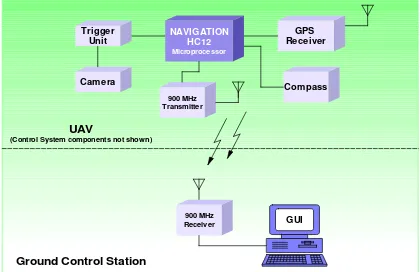
Based on the literature review carried out, the hardware available and the project specification, the chapter presents the overall system design concept and architecture as shown at the highest level in the system development methodology of Chapter 1. A block diagram of the system is shown in Figure 4. The details of the design and testing of these systems is discussed in depth in the following chapters.
4.1 Original Concept
Before UAV takeoff, the Ground Control Station (GCS), consisting of a laptop PC (Dell Inspiron 510m), GUI and XStream 900MHz Transceiver will be connected to the UAV via a RS232 wireless link. Once connected, flight path information consisting of four latitude and longitude waypoints will be entered into the GUI, where they will be sent to the ‘Navigation HC12’ on the UAV. The ‘Navigation HC12’ microprocessor is connected to the Garmin GPS 35 LP TracPak™ antenna/receiver, the V2X 2-axis compass module, an electronic trigger unit and Minicam TDC-32 camera and XStream 900 MHz Transmitter.
The UAV is controlled by a user during takeoff, on a separate radio-controlled communications channel. Once in the air, the UAV is switched to autonomous flight at which time the ‘Navigation HC12’ commences provision of heading error information from current position to the first waypoint. The 900MHz transceiver connected to the HC12 will downlink telemetry information to the GUI including latitude, longitude, altitude, satellite and receiver status, heading error and compass heading information.
The camera is electronically triggered once over every waypoint by the ‘Camera Trigger Program Module’ programmed into the ‘Navigation HC12’ EEPROM. Once all four waypoints have been passed within a five metre radius, the UAV control is switched back to remote-control by the user, where it can then be landed. Surveillance photos can then be accessed on the GCS (serial cable connection).
GPS Receiver
Compass Trigger
Unit
Camera
NAVIGATION HC12 Microprocessor
900 MHz Transmitter
900 MHz
Receiver GUI
UAV
(Control System components not shown)
[image:39.595.128.548.372.644.2]Ground Control Station
4.2
Resource Analysis
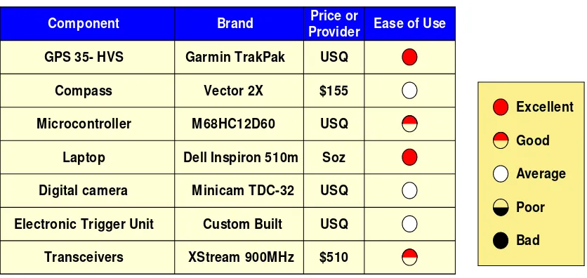
[image:40.595.124.542.409.607.2]To build a prototype autonomous UAV navigation and user interface, there are many components and resources required to fulfil the objectives up to and including the final UAV system integration. The resources used include supporting personnel: my supervisors and Engineering faculty technical staff. The university provided a room and equipment to carry out all testing and the provision of miscellaneous parts: soldering equipment, power supplies, cables, passive components, oscilloscope and multimeters. The library, Institute of Electrical and Electronics Engineers (IEEE) and Engineers Australia have provided invaluable educational resources. The hardware resources selected for use in this project are shown in Table 1. The prices for components that were not bought specifically for this project have not been included.
Table 1- Hardware Resources Used
Ease of Use Brand
Component
GPS 35- HVS Garmin TrakPak
Compass $155 Microcontroller Vector 2X M68HC12D60 Laptop Digital camera
Electronic Trigger Unit
Transceivers XStream 900MHz
Dell Inspiron 510m USQ USQ Price or Provider Soz Custom Built $510 Excellent Good Average Poor Bad
Minicam TDC-32 USQ
USQ
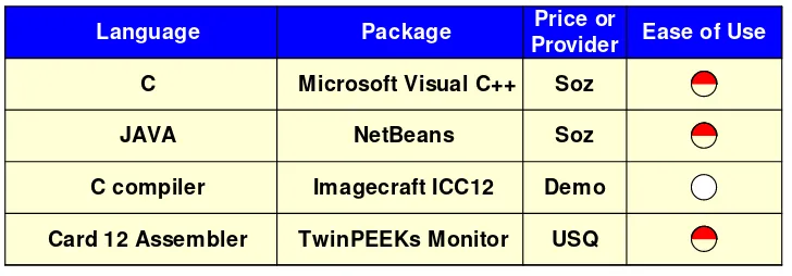
Table 2- Software Resource Used
Ease of Use Language
C Microsoft Visual C++
JAVA
Package
C compiler Imagecraft ICC12
Card 12 Assembler TwinPEEKs Monitor
Price or Provider Soz Soz Demo USQ NetBeans
The total cost of resources bought specifically for this project was $665. A test trolley was manufactured out of recycled materials. The model aircraft currently available for use is the GW/SlowStick. The specifications for this remote controlled aircraft are shown in Table 3. This aircraft was used in Michelle Keeffe’s project in 2003. It was chosen because of its simplicity, low cost and ease of use. Whilst it is an inherently stable aircraft, its payload capabilities have meant that the complete navigation and guidance system has not been installed on the UAV. Model aircraft alternatives were investigated but it became clear that the cost of a new aircraft with higher payload capabilities was not feasible this year. All other resources required were available from early on in the life of the project.
Table 3- GW/SLOWSTICK aircraft
Characteristic Value Length Wing Span Wing Area Flying Weight Wing Loading Battery Required Power System Radio Required 954 mm 1176 mm
32.64 dm2
405~440 g
12.4~13.5 g/dm2
2~4 Channel Radio 11.1 V lithium polymer
brushless motor 1200mAh
[image:41.595.183.472.485.694.2]investigated as they depended very much on the UAV for which the system would be integrated. A suitable remote control aircraft was not available, so these types of protection were not designed. A custom made test trolley was manufactured to carry out testing of the Navigation and User Interface system. This trolley is a basically a plank of wood with four wheels, a GPS tower and a broom like handle for pushing. The final navigation circuit was placed in a protective housing to keep it free from dust.
Chapter 5
Risk Assessment
Aviation activities are inherently dangerous. Whilst UAVs offer a safe alternative to piloted aircraft by avoiding the necessity for personnel to be exposed to the risk of flying, they then require completely reliable autonomous and/or remote control to ensure the UAV does not represent a risk to people, equipment or structures on the ground. The risk of aircraft failure in a general sense is not acceptable due to the severe consequences. For this reason, all general aircraft are designed with redundant flight critical systems. This ensures that if a system required for safe flight fails, a back-up system will take over with no reduction in performance. This enables the mission to be completed or safe landing of the aircraft and as such, safe return to ground of all personnel and equipment. This project has been carried out with safety as a major priority, and a risk management plan was implemented early on to ensure all risks were mitigated where necessary.
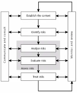
Figure 5- Risk Management Process Overview
5.1
Identifying Risks
5.2
Evaluating Risks
A qualitative method for evaluating the level of risk posed by an event has been adopted for this project. The risk analysis consists of first assessing the likelihood of the event happening and the potential consequences should that event occur. Criteria for grading likelihood and consequences are provided in Table 4 and Table 5, respectively.
Table 4- Likelihood Rating Criteria
LIKELIHOOD RATING DESCRIPTION
Rare May occur only in exceptional circumstances
Unlikely Could occur at some time
Moderate Might occur at some time
Likely Will probably occur in most circumstances
Almost Certain Expected to occur in most circumstances
Table 5- Consequence Rating Criteria
CONSEQUENCE RATING DESCRIPTION
Insignificant Inconvenience. Minimal or no impact. Minor
• Small but acceptable degradation in performance..
• Unable to meet an intermediate milestone but able to meet all major milestone dates.
Moderate • Tolerable but significant degradation in performance. • Unable to achieve one major milestone date.
Major
• Significantly degraded performance to the point where project success is questionable.
• Unable to achieve more than one major milestone date.
Severe • Unacceptable performance resulting in project failure. • Unable to achieve acceptance milestone date.
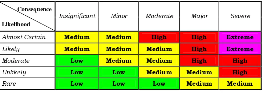
The likelihood and consequence grading are combined to form a single risk level matrix shown in Table 6. This matrix has been taken from the RAN Aviation Safety Manual (ABR 5147 Annex C), and is the standard Department of Defence risk matrix. The risk levels have been categorised as:
MEDIUM. The risk event, were it to occur, would be likely to have some undesirable consequences for the project, but would be unlikely to cause it to fail;
HIGH. The risk event, were it to occur, would have a significant impact on the perceived or actual success of project, and could even cause the project to fail; and
[image:46.595.116.543.315.467.2]EXTREME. The risk event, were it to occur, would probably cause the project to fail, or give rise to unacceptable circumstances (such as frequent adverse user acceptance and operational failure) attributable to the project.
Table 6- Risk Level Matrix
Consequence
Likelihood
Insignificant Minor Moderate Major Severe
Almost Certain Medium Medium High High Extreme
Likely Medium Medium Medium High Extreme
Moderate Low Medium Medium High High
Unlikely Low Low Medium Medium High
Rare Low Low Low Medium Medium
5.3
Risk Control
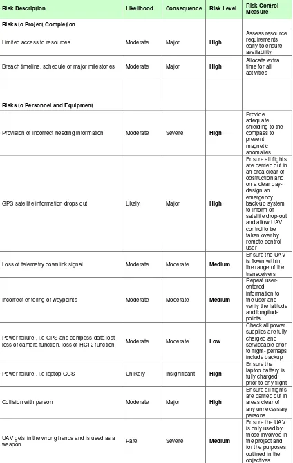
Table 7- Risk Assessment
Risk Description Likelihood Consequence Risk Level Risk Control Measure
Risks to Project Completion
Limited access to resources Moderate Major High
Assess resource requirements early to ensure availability
Breach timeline, schedule or major milestones Moderate Major High
Allocate extra time for all activities
Risks to Personnel and Equipment
Provision of incorrect heading information Moderate Severe High
Provide adequate shielding to the compass to prevent magnetic anomalies
GPS satellite information drops out Likely Major High
Ensure all flights are carried out in an area clear of obstruction and on a clear day- design an emergency back-up system to inform of satellite drop-out and allow UAV control to be taken over by remote control user
Loss of telemetry downlink signal Moderate Moderate Medium
Ensure the UAV is flown within the range of the transceivers
Incorrect entering of waypoints Moderate Moderate Medium
Repeat user-entered information to the user and verify the latitude and longitude points
Power failure , i.e GPS and compass data lost-
loss of camera function, loss of HC12 function- Moderate Moderate Low
Check all power supplies are fully charged and serviceable prior to flight- perhaps include backup
Power failure , i.e laptop GCS Unlikely Insignificant High
Ensure the laptop battery is fully charged prior to any flight
Collision with person Moderate Major High
Ensure all flights are carried out in areas clear of any unnecessary persons
UAV gets in the wrong hands and is used as a
weapon Rare Severe Medium
Unskilled pilot used for take-off landing and for
emergency control of UAV Likely Moderate Medium
Ensure any pilot is experienced and that all CASA guidelines are followed
UAV is flown above 400ft Moderate Moderate Medium
Chapter 6
Navigation System Hardware Design and
Implementation
This chapter describes the selected navigation and guidance system hardware and how it was developed. The components selected for use are those shown in the system architecture block diagram in Chapter 4. They are now discussed in detail. The requirements and limitations as outlined in Chapter 1 have been analysed to ensure any design falls within these guidelines. Development tools employed throughout the project for successful design and implementation of components is detailed. The testing of each of the components is described along with any interface considerations necessary for successful integration.
6.1
Flight Computer
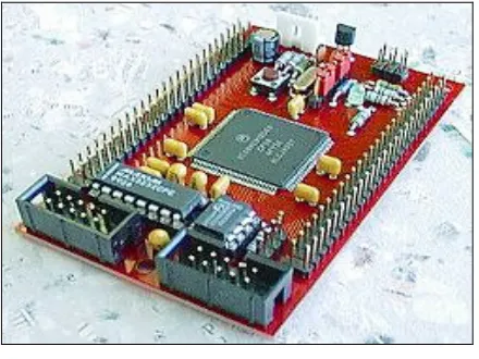
The brain of the Navigation and User Interface system is the 68HC(9)12D60 microcontroller unit. It is a 16 bit member of Freescale’s HC12 Microcontroller family and offers additional features that aid in the development process. In particular, the microcontroller card is equipped with the TwinPEEKS monitor program which allows easy download and programming of Flash and EEPROM memory, without the need for any additional hardware tools (Elektronikladen 2005). Other features include:
• 1 KB EEPROM
• 2 KB RAM
• SPI, 2 x SCI
• Enhanced Capture Timer
• 4 Channel Pulse Width Modulator
• 16 Channel 10 bit A/D Converter
• 8 MHz operation at 5V
• CAN 2.0A/B bus interface with CAN driver
[image:50.595.217.437.373.538.2]Appendices B and C show the block diagram and schematic of the 68HC(9)12D60. The HC12 has been labelled ‘Navigation HC12’ to differentiate it from the HC12 used in the Automatic Flight Control portion of the prototype UAV (Littleton 2005) The 68HC(9)12D60 is shown in Figure 6.
Figure 6- Card 12
Figure 7- HC12 Port S
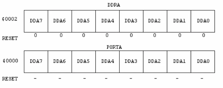
The GPS is connected to SCI1 and the compass is connected to the SPI. The Ground Control Station laptop is connected via SCI0 through the 900 MHz transceiver used for uploading the initial user-selected waypoints and then for telemetry downlink of UAV status whilst in flight. The CAN bus has been set up to send data from the Navigation HC12 to the Automatic Flight Control HC12. The input/output ports A and B are used for controlling the compass and camera trigger module where necessary. These ports are controlled by assigning them either an input or output by writing a 1 (HIGH) or a 0 (LOW) to the corresponding bit of the data direction register (DDRA/B). On reset, DDRA and DDRB are set to $00 which means they are inputs by default. For example, to make bits 3-0 of PORTA inputs, and bits 7-4 outputs, it is necessary to write 0x0f to DDRA. Then, to send data to the output pins, it is as simple as writing directly to PORTA. When reading from PORTA, input pins will return the value of the signals on them (0 = 0V, 1 = 5V); output pins will return the value written to them. A block representation of PORTA and its data direction register are shown in Figure 8.
The HC12 has capabilities above and beyond the necessities of this project, but its ease of use and processing power offer a platform for a reliable embedded navigation system for the prototype UAV. The navigation and guidance ‘Waypoint Path Planner Algorithm’ and ‘Camera Trigger Module’ are programmed into the EEPROM and the user-entered waypoints are stored into RAM for every mission to be carried out. The ‘navigation HC12’ is programmed using C language for two reasons. Firstly, a suitable HC12 C-compiler demo was available for use, and secondly, C is an easy and simple programming language to carry out the tasks required. Assembly language programming was not considered viable due to the complexity of the trigonometric functions to be used in the navigation algorithm. Details of program implementation are discussed in Chapter 8.
6.1.1
SPI
The Serial Peripheral Interface (SPI) is used primarily for synchronous serial communication between a host microprocessor and peripherals. It can also be used to connect two HC12 microprocessors together, but this feature has not been used in this project. A data byte can be shifted in and/or out one bit at a time. The SPI in the HC12 contains the four necessary signals for SPI communication. Two SPI modules connected in a generic Master-Slave configuration are shown in Figure 9.
In the master SPI, the bits are sent out of the MOSI pin and received in the MISO pin. The bits are shifted out and stored in the SPI data register, SP0DR, and are sent out most significant bit first (bit 7). When bit 7 of the master is shifted out through the MOSI pin, a bit from bit 7 of the slave is being shifted into bit 0 of the master via the MISO pin. After 8 clock pulses or shifts, this bit will end up in bit 7 of the master. In the HC12 the least significant bit is sent out first by setting the LSBF bit to 1 in the SPI Control Register. The clock which controls how fast the bits are shifted out and into the SP0DR, is the signal SCLK at PS6. The frequency of this clock is controlled by the SPI baud rate register, SP0BR. The SS pin must be low to select a slave. This signal can come from any pin on the master, including its SS pin when it is configured as an output. The SPI registers in the HC12 are shown in Table 8.
Table 8- HC12 SPI registers
Name
Register Address
Description
SP0CR1 00D0 SPI Control Register 1
SP0CR2 00D1 SPI Control Register 2
SP0BR 00D2 SPI Baud Rate Register
SP0SR 00D3 SPI Status Register
SP0DR 00D5 SPI Data Register
Table 9- SPI clock rate selection
SPR[2:0]
Divisor
Frequency
000 2 4.0 MHz
001 4 2.0 MHz
010 8 1.0 MHz
011 16 500 KHz
100 32 250 KHz
101 64 125 KHz
110 128 62.5 KHz
111 256 31.25 KHz
The details of SPI communication implementation are discussed in Chapter 8, which describes the program necessary to initiate SPI communication with the compass.
6.1.2
SCI
The 68HC12 has two Serial Communication Interfaces, each providing a Transmit Data and a Receive Data signal suitable for a RS232 interface. Each SCI can be configured for eight or nine data bits, the most significant can be configured as an even or odd parity bit which is generated automatically on transmission and checked on reception. There is always a single stop bit. Transmission data rates can be selected independently for each SCI, however, the transmit and receive rate for a single SCI must be the same (Almy 2004). The SCI1 connection to the GPS is configured for reception of data only. The SCI0 connection to the Ground Control Station is set up for reception of data to allow for the user-entered waypoints to be downloaded to RAM on start up. The SCI0 connection is then configured (via software) for transmission of data to enable telemetry downlink to the Ground Control Station. Whether transmitting or receiving, the following process must be used to initialise communications with the SCI and its peripherals:
two 8-bit registers considered together as a 16-bit baud rate control register. Table 10 details the necessary values to be set in the SCI Baud Rate Control Register. This table follows the following formula for calculating the necessary enterable Baud Rate (BR).
16 x
MCLK BR
SCI Baud Rate
=
Equation 3- Baud Rate Calculation
BR is then the value written to bits [12:0] of SCIBDH.
Table 10- Baud Rate Generation
Desired SCI Baud
Rate
BR Divisor for
MCLK = 8 MHz
110 4545
300 2273
600 833
1200 417
2400 208
4800 104
9600 52
14400 35
19200 26
38400 13
The GPS defaults to 4800 baud. This means that to receive data from the GPS, the SCIBDH gets set to 104 decimal. The Ground Control Station can communicate at a variety of baud rates as dictated by the laptop PC. The baud rate selected and set on both the laptop and SCI0 is 9600 baud and as such, the SCIBDH is set to 52 decimal.
of one start, eight data and one stop bit. SCxCR2 is set to 12 decimal to enable transmit and receive anytime.
3. The next step requires the SCI status register be polled to check for either a Transmit Data Register Empty Flag (TDRE = 1) or a Receive Data Register Full Flag (RDRF = 1). When transmitting data, once TDRE = 1, the SC0DRH and SC0DRL data registers may be written to for sending data to the applicable peripheral (in this case the Ground Control Station). When receiving data, once RDRF = 1, the SC1DRH and SC1DRL may be read from.
6.1.3
CAN
The Controllable Area Network (CAN) is a serial communication protocol that supports distributed real-time control applications. The bus in this project is used as the connection between the ‘Navigation HC12’ and the ‘Automatic Flight Control HC12’ for the transmission of heading error and altitude.
Though conceived and defined by BOSCH in Germany for automotive applications, CAN is not restricted to that industry. The CAN protocol fulfills the communication needs of a wide range of applications, from high-speed networks to low cost multiplex wiring (Huang 2003).
The Freescale Scalable CAN module (MSCAN) is an advanced communications controller, implementing the CAN protocol, with these features as described in the Motorola Advanced Information Booklet (2000):
• Implementation of CAN version 2 parts A and B
• Standard (11-bit) and extended (29-bit) data frames
• 0 to 8 bytes data length
• Programmable bit rate up to 1 Mbps
• Support for remote frames
• Double buffered receive
• Flexible maskable identifier filter supports alternatively two full size extended identifier filter, four 16-bit filters, or eight 8-bit filters
• Programmable wakeup functionality with integrated low-pass filter
• Programmable loopback mode supports self-test
• Separate signaling and interrupt capabilities for all CAN receiver and transmitter error states (warning, error passive, bus-off)
• Programmable MSCAN clock source (either the CPU bus clock or the crystal oscillator output). Low-power sleep mode.
CAN is divided into data link and physical layers. The physical layer defines how the signals are actually transmitted; bit timing, bit encoding and synchronization.
Information on the CAN bus is sent in fixed formats of different but limited lengths. When the bus is free, any connected node may start to transmit a new message. For the application required in this project, the only nodes connected will be the automatic flight control system and the Navigation and User Interface systems. The Navigation and User Interface system will transmit heading error and altitude in the required format (as a character array) onto the CAN bus so that the Flight Control System can access it when ready. The CAN system does not specify node addresses in a message. Instead, it uses an identifier to describe the content of the message. The identifier does not indicate the destination of the message; instead, the meaning of the data is described. The nodes connected to the bus network are able to decide by message-filtering whether the data is to be read by them or not. This feature is not required in this application as the Automatic flight control system will always be the recipient of the transmitted messages and as such, these filters have been disabled in the software implementation described in Chapter 8.
6.2
Development Tools
6.2.1
TwinPEEKs Monitor Program
The TwinPEEKs monitor program is a ROM Monitor utility which supports uploading of user program code to the on-chip EEPROM of the HC12. The Monitor Program is able to display and modify the memory contents of the HC12 and can also be used to commence execution of the user program in real-time.
The Monitor occupies 2 KB of EEPROM Code space leaving 2 KB for user program code. The Monitor is pre-programmed into the EEPROM of the 68HC(9)12D60 development board so the Monitor Program can communicate with the Monitor when the board is powered up.
[image:58.595.157.503.459.619.2]TwinPEEKs allowed the programming of the final navigation solution to be uploaded to the HC12 EEPROM in assembly language source file code, as is produced by the ImageCraft compiler discussed below. The memory map of the 68HC(9)12D60 is shown in Table 11.
Table 11- 68HC(9)12D60 Memory Map
$0000 - $01FF MCU Control Registers
$0200 - $07FF 2 KB RAM
$0C00 - $0FFF 1 KB EEPROM
$1000 - $7FFF 28 KB (lower) Flash Memory Array $8000 - FFFF 32 KB (upper) Flash Memory Array Boot Block (containing Monitor code):
$E000 - $FFFF
$8000. In this way it is possible to automatically start a user program without changing the Reset Vector, which resides in the write-protected Boot Block area.
6.2.2
ImageCraft ICC12 V6
The ImageCraft C ICC12 Development Environment is a program for developing HC12 microcontroller applications using the ANSI standard C language. Its main features are:
• An intuitive Windows 95/NT native Integrated Development Environment (IDE) with integrated editor and project manager. Source files are organized into projects. Editing and building can be done wholly within the environment. Compile time errors are displayed in the status window, and with a click of the mouse button, you can jump to the lines that cause the errors in the editor window. The integrated project manager generates a standard makefile that you can view and use directly if desired.
• The IDE drives an ANSI C command line compiler that is normally transparent in operation. However, if you wish, you can interact with the compiler directly using the command prompt program. The compiler is a set of native 32-bit programs and understands long file names.
ICC12 enables the development, compilation, linking and debugging of C source code and produces an assembly language source file version of the C source code that is executable on the HC12 microprocessor. The benefits of this software cannot be overstated. The amount of time and effort required in algorithm implementation and hardware integration has been greatly reduced by avoiding the need to develop assembly language source files from scratch.
6.3
Sensors
current heading information to then calculate the heading error (and thus amount of turn required) in order to ensure the UAV heads towards the next waypoint. The hardware design and integration issues of these sensors are now discussed with the software implementation discussed in Chapter 8.
6.3.1
GPS
The GPS used in this project is the GARMIN GPS 35 LP TracPakTM, model
GPS35-HVS. This product is a receiver with an embedded antenna that provides one second navigation updates and low power consumption. This GPS offers two RS-232 compatible full duplex communication channels and user-selected baud rates that allow maximum interface capability and flexibility. The GPS GGA message is used to provide position information to the system as well as telemetric information; altitude and GPS status to the Ground Control Station GUI. Data parsed from the GPS to the microprocessor is GPS status, time, latitude, longitude, and altitude. The altitude measurements are passed directly to the control system microcontroller without any manipulation. The GPS status is used to indicate to the Ground Control Station any loss in quality of the received GPS message. By including this feature, the high level risk identified in the risk assessment shown in Chapter 5 is mitigated. The user is informed of a loss of GPS signal quality, in which case the UAV control can be handed back to manual remote control for safe landing of the UAV. Whilst the GPS receiver offers reliable long term position information, its susceptibility to environmental interference means that the reliability of the GPS can only really be guaranteed on non-cloudy days away from any physical obstructions that may impose a shadow on the GPS receiver/ antenna. An extract from the GPS35-HVS specification detailing the NMEA sentences received is included in Appendix D. The following is a summary of the more pertinent features:
• Full navigation accuracy provided by the Standard Positioning Service (SPS),
• Compact design ideal for applications with minimal space,
• Internal clock and memory are sustained by a rechargeable memory backup battery. The battery recharges during normal operation. This redundant feature ensures the reliability of data received from the GPS.
• User initialisation is not required ensuring ease of use and an ‘off the shelf’ like solution.
• Two communication channels and user selectable baud rates allow for maximum interface capability and