FRACTURE MANDIBLE – A CLINICAL &
BIOMECHANICAL STUDY
Dissertation submitted to
THE TAMILNADU Dr. M.G.R. MEDICAL UNIVERSITY
In partial fulfillment for the Degree of
MASTER OF DENTAL SURGERY
BRANCH III
This is to certify that this dissertation titled “FACTORS INFLUENCING FIXATION OF PLATES IN FRACTURE MANDIBLE – A CLINICAL & BIOMECHANICAL STUDY” is a bonafide record of work done by Dr.V.KIRUTHIKA under my guidance during her postgraduate study period 2013 - 2016.
This dissertation is submitted to THE TAMILNADU Dr. M.G.R. MEDICAL UNIVERSITY, in partial fulfillment for the degree of MASTER OF DENTAL SURGERY in Branch III – ORAL AND MAXILLOFACIAL SURGERY.
It has not been submitted (partially or fully) for the award of any other degree or diploma.
Professor, HOD and Guide Principal
Dr. L.DEEPANANDAN, M.D.S., Dr. V. PRABHAKAR, M.D.S.,
Department of Oral & Maxillofacial surgery, Sri Ramakrishna Dental College & Hospital, Sri Ramakrishna Dental College & Hospital, Coimbatore.
Coimbatore.
Candidate Dr. V. KIRUTHIKA
Department of Oral & Maxillofacial surgery, Sri Ramakrishna Dental College & Hospital,
Coimbatore.
Date:
First and foremost, I would like to express my sincere gratitude to my guide
Dr. L. Deepanandan, M.D.S., Professor and Head, Department of Oral and
Maxillofacial Surgery, Sri Ramakrishna Dental College, for his unwavering guidance,
for his patience, motivation, enthusiasm, and immense knowledge. His guidance
helped me in getting a better shape during the time of my course, to understand and
complete the dissertation. I could not have imagined having a better guide for my
dissertation.
I also express my sincere heartfelt gratitude to Dr. M. S. Senthil Kumar,
M.D.S., Associate Professor, Department of Oral and Maxillofacial Surgery, Sri
Ramakrishna Dental College, for his constant support and encouragement throughout
the duration of my course, scholarly support throughout this journey.
I also express my sincere heartfelt gratitude to Dr. R. Kannan, M.D.S.,
Reader, Department of Oral and Maxillofacial Surgery, Sri Ramakrishna Dental
College, for his innovative ideas, suggestions, valuable criticism and constant
encouragement throughout the duration of my course.
I also express my sincere heartfelt gratitude to Dr. M. A. I. Munshi, M.D.S.,
and Dr. R. S. Karthik, M.D.S.,Readers, Department of Oral and Maxillofacial
Surgery, Sri Ramakrishna Dental College, for their constant scholarly support,
Lecturer, Department of Oral and Maxillofacial Surgery, Sri Ramakrishna Dental
College, for his valuable help, support and guidance.
It would be unfair of me if I fail to acknowledge the timely help and constant
encouragement from my colleague Dr. M. Geetha, whose support helped me to
overcome difficulties.
I also express my sincere thanks to my beloved seniors Dr. V.R. Rajinikanth
& Dr. M. Suganthi for their help and support.
I also express my sincere thanks to my beloved juniors Dr. Bhargavi
Sivarchaka, Dr.Gayathri R. Nair, Dr. G. Karthik Rajan & Dr. N. Santhoshi
Revathy for their help and support.
Above all, I wish the Almighty for blessing me with such wonderful parents,
sister, brother-in-law and nephew. Their support, love, sacrifices and encouragement
have made me to achieve my dream.
I thank the Almighty for guiding me throughout my life.
AIM: The symphysis and angle region are the most frequent sites for mandibular fractures. Direct application of 2.0mm conventional and locking titanium miniplates are the most commonly used intraoral open reduction and internal fixation technique today. Anatomic and biomechanical limitations continue to make this application technically challenging with a considerable complication rate. Such incongruences are analysed with respect to the complex biomechanical behaviour of the mandible. METHODOLOGY: Individual human mandible geometry, the specific bone density distribution, and the position and orientation of the masticatory muscles were evaluated by performing computed tomography scan of the cadaveric human mandible. Dimensional changes in the holes of the 2.0mm (Orthomax, Leforte and Synthes) titanium conventional and locking miniplates/screws were evaluated using RAPID-I Precision Vision Measuring System (VMS) pre and post adaptation to angle and symphysis region. The average bite forces of 15 patients who were operated for symphysis and angle fractures were measured using AXPERT electronic bite force gauge at 5 bite points viz right molars, right premolars, left molars, left premolars and anteriors. Three Dimensional Finite Element Analysis (3D FEA) was performed for symphysis and angle fracture sites with Temporomandibular Joint remaining static. Deflection, stability, mechanical stress over bone, maximal stress over miniplate, fracture gap and direction of displacement evaluated for loading conditions.
locking. Fracture gap was more of about 0.86241mm in Orthomax conventional and least of about 0.01804mm with Leforte locking. Angle fracture fixation showed maximum deflection of 5.93459mm with Orthomax conventional and least of about 3.00287mm with Synthes locking plates. Maximum stress over bone was more of about 379.81 Mpa for Orthomax conventional and least of about 309.63 MPa for Synthes locking plates. Stress over plate was more of about 2114.62 MPa in Orthomax conventional and least of about 833.457 MPa in Synthes locking. Fracture gap was more of about 2.2708mm in Orthomax conventional and least of about 1.86241mm with Leforte locking.
CONCLUSION: Consecutive rapid failure of the miniplates could not be prevented when the angle and symphysis region are loaded with vertical bite forces. The more stable plate is Synthes locking plate followed by Leforte locking plate for the symphysis region and angle region. The static yield limit of titanium exceeds, when geometry and dimension of the miniplates get altered, while adapted to angle and symphysis region. Hence, the dimensional changes in the holes of miniplates occurring during adaptation of the plate to the fracture site are also a factor to be considered for stability of the plate.
LIST OF ABBREVIATIONS
CAD Computer Aided Design
CT Computed Tomography
2D Two Dimensional
3D Three Dimensional
FEA Finite Element Analysis
FEM Finite Element Model
viz namely
TMJ Temporomandibular joint
IMF Inter Maxillary Fixation
N Newton
N/mm2 Newton per millimeter squared
MPa Mega Pascals
GPa Giga Pascals
mm millimetre
cm centimetre
Kg Kilogram
DICOM Digital Imaging and Communications in Medicine
IGES Initial Graphics Exchange
Specification
Ti Titanium
SRIF Semi Rigid Internal Fixation
VMS Vision Measuring System
avg Average
CONTENTS
TITLE
PAGE NO
1. Introduction
1
2. Aims & Objectives
4
3. Review of Literature
5
4. Materials and Methods
31
5. Results
46
6. Discussion
55
7. Summary & Conclusion
63
8. Bibliography
65
1
The continued interest on biomaterials, motivated Physicians and Maxillofacial surgeons pay a lot of attention towards investigation of mechanical properties of bone tissue and other biocompatible materials. The first investigation on bone mechanical properties commenced in the nineteenth century.1 The Rational structure of bone and the effective resistance of bone tissue to mechanical loads can be used as a prototype for development of new composite materials and designs that becomes compatible and economical to be used in medical practice.2,3,4,5,6,7,8,9
Mandibular fractures are the highest of all the facial bone fractures in any maxillofacial trauma situation.5,6 Mandibular fracture affects healthy breathing, food consumption and clear conversation. The above, when not handled with care, causes serious deformities affecting the normal life of the patient and leading to secondary correction.
2
(SRIF) method is not sufficiently explored. One of the types of SRIF is Miniplates osteosynthesis. This helps early mobilization of the mandible for normal functioning and also avoids wires /splints/long term arch bars (Nonrigid fixation technique) for stability of the fractured site for osteosynthesis. Moreover Nonrigid fixation technique is old and has enough number of complications to be specified which could be overcome by SRIF.20
Advantages of SRIF:
Increased fractured segment stability (comparatively)
Prevents long-term intermaxillary fixation
Enhances fast bony osteosynthesis.
MOTIVATION OF THE RESEARCH
During normal activities, fractured mandibular bone is exposed to cyclic loading.21 Highest stress arise from the cyclic loading action when applied vertically on to the occlusal and incisal region of the mandibular teeth. This may compromise the initial fixation of the miniplates which leads to bone tissue resorption and loss of contact between miniplates and bone tissue. Adequate treatment choices prevent the consequences of the given stress. The design and dimension of the miniplates plays a major role in the stress distribution over the parabolic (horse shoe shape) mandibular bone.22
3
miniplate design, may induce additional stress concentration over material and bone tissue structure. The assessment of stress and deformation, that induce cyclic loading, is essential to predict the risk of failure.19,25,26
Manual experimentation needs physical models, which are inconvenient, costly and difficult to simulate normality in certain situations. This paved the way for development of virtual analysis using three dimensional (3D) Finite Element Modelling (FEM) which is more convenient and solves all complex situations in reproduction.10,27 The Finite Element Analysis (FEA) method is widely accepted replacement for photo elasticity tests, as it is one of the most practical and reliable methods. FEA numerically analyses mechanical behaviour of biological objects.
Within this thesis, the focus will be on simulating the fixation of angle and symphysis fractures of dentulous mandible using 2.0mm titanium miniplates both conventional and locking plates along the Champy’s line of osteosynthesis. Loading cases can range from fast movement and small forces when talking, to slow or no movement and large forces during mastication. The aim of the study is to evaluate the stability, flexural and compressive strength and deflection of miniplate system, on occlusal forces in symphysis and angle fractures of mandible elicited on human cadaveric mandible model with Finite Element Analysis (FEA) by mechanical application of vertical load.
4 The purpose of the Finite Element study is
1. To evaluate dimensional changes, stability and deflection of miniplates after adapting to the symphysis and angle region.
2. To evaluate mechanical stress over bone.
3. To evaluate maximum stress bearing area over miniplates.
4. To evaluate the distance between the reduced and fixed fractured segments (fracture gap) after vertical load application.
5
Michelet F.X. etal (1973)18 did an analysis on 300 cases involving fractures of the facial bones that were treated using malleable non compression miniplates made of Vitallium. Monocortical screws were used for fixation and a 3 year follow up was done. They concluded that the miniplates were fixed through adequate intraoral access and there was perfect adaptation of the fractured segments. The complications were also reduced to 5 % and also the requirement for intermaxillary fixation was reduced.
James P. Ralph and Angelo A. Caputo (1975)5 prepared replicas of dentate human mandible in photoelastic liquid epoxy material to study the stresses that develop within the structure of mandible in response to the application of various loads. Occlusal loading was simulated and the stresses generated within the models were examined by 3D photo elastic stress analysis in three different loading conditions. It provided a means for demonstrating and analyzing the stresses likely to be imposed on the structure of mandible by various clinical procedures.
6
Franco Mongini etal (1979)3 studied relationship between the shape and structure of the mandible & their stress pattern distribution when occlusal loads were simulated. 10 human skulls 4 males and 6 females aged 22 to 53 were evaluated. Right & left lateral cephalographs were taken to know the internal density of the mandibles and 500 points were graphically plotted using software. Occlusal loads were simulated & isoclinics were in plane polarized light & relation between the occlusal load & stress pattern recorded on the brass replica of the model. Results showed stress pattern prolongation over the angle, ramus & condyle predominantly. No correlation of the orientation pattern with sex & age were observed.
Proffit WR, Fields HW and Nixon WL (1983)59 studied accurate measurement of occlusal forces in humans and provided data for normal and long face adults. The study used both quartz and foil based piezoelectric force transducers to evaluate occlusal forces during swallow, simulated chewing and maximum effort in 14 long face and 21 normal individuals at 2.5mm and 6.0 mm molar separation. The results of the study showed that the occlusal forces in normal and long-face adults at 2.5mm and 6.0mm molar separation during swallowing was 2.9kg, 4.8kg, 1.1kg, 1.8kg respectively, chewing was 13.5 kg, 16.2kg, 4.2kg, 4.8kg respectively and the mean bite force was 31.0 kg, 35.6kg, 11.2kg and 15.5kg respectively. The study concluded that the long-face individuals had significantly less Occlusal force than do individuals with normal vertical facial dimensions.
7
the patients, wound dehiscence in 12%of the patients and malocclusion in 8 % of the patients, infection in 4 % of the patients and sensory disturbance in 4% of the patients. Though complication occurred, plating resulted in earlier healing and jaw opening. Intermaxillary fixation could be used as a supplement in cases of comminuted mandibular fractures.
Charles H. Gibbs etal (1986)58 designed & developed Gnathodynamometer for analysing bite forces of human. It consisted of two stainless steel plates separated by a steel sphere that balanced biting force between right and left sides. Gnathodynamometer was placed bilaterally between premolars, first molars, and second molars. The interocclusal separation between the posterior teeth was approximately 12 mm. The greatest bite strength, 975 lbs (443 kg), was recorded from a 37-year-old man. Bite strength of 975 lbs (443 kg) was found for one subject in this study which was more than twice any previously reported value and 2.8 times more than the value that was reported for Eskimo. Bite strength in some bruxer-clenchers was six times more than that of a nonbruxer.
8
The Champy plate served in the juxta-alveolar region created clearly visible compression stresses in the mandibular base on application of loads. The study concluded that the Champy method was the most resistant to vertically bending forces and satisfied the final requirements for a functionally stable osteosynthesis.
9
occlusal load were calculated. The study evaluated the point at which the lowest maximal bone plate strain occurred and the site at which all forces and torques cancel each other. The study concluded that the type of fracture (serrated or smooth), the strength and shape of the osteosynthesis plates influenced the choice and positioning of bone plates and screws used for fixation of mandibular fractures.
Luis A. Passeri etal (1993)20 analysed the complication rates associated with closed reduction and open reduction using non-rigid means of fixation in 96 patients with mandibular angle fractures. The results of the study indicated rate of infection was 13%. Four cases had combined infection with malunion and malocclusion. The study concluded that the mandibular angle fractures were associated with a significant number of complications, regardless of the method of treatment.
10
Byung Ho Choi etal (1995)60 did clinical and in vitro evaluation of mandibular angle fracture fixation with the two-miniplate system by placing one plate at the superior border and a second plate is applied at the inferior border of the buccal cortex compared with single miniplate placed according to Champy’s method. Opening of fracture gap in angle fracture was present in Champy's method and no visible opening of gap in angle fracture with two-miniplate-fixation technique. This was confirmed when 40 mandibular angle fractures were treated with the two-miniplate fixation technique. Bone healing took place in all cases without evidence of osteomyelitis. Hence two miniplate fixation was superior to conventional technique in stability and resistance in angle fracture.
11
James W. DeVocht etal (1996)55 developed a two dimensional finite element model to simulate in-vivo biomechanics of TMJ over the range of normal motion. Model was developed using ABAQUS software with slide line elements that allowed large displacements and arbitrary contact of surfaces. The three main components of the model were the mandibular condyle, articular disc, and glenoid fossa region of the temporal bone, which were all modeled as deformable bodies. Continuous motion was simulated by doing a static analysis for each of many small steps. A parametric study was performed by determining the maximum stress in each of the three main components as a function of the elasticity of the articular disc. This model suggested that muscle contraction was not required to maintain proper disc position. Normal motion resulted in relatively high stresses deep in the glenoid fossa.
12
Righi E. etal (1996)22 experimented ten segments of bovine scapula bone. Five of which fixed with 4-hole titanium miniplate and other five fixed with 6-hole Double Y plate and adapted to a tension test machine. Shear tests were recorded. On the basis of the test results, two simple computer models were developed. No significant difference in stress pattern was evident between the mechanical and computed tests. The most critical sections were located near the hole proximal to the osteotomy and the microscopic findings confirmed this. This suggested that straight miniplate design would provide sufficient stability and a high degree of anatomical adjustment of the system.
13
mechanical property of the implant should also be considered before formulating a criteria for the number of plates and position on the bone.
Joerg M. Wittenberg etal (1997)2evaluated the effectiveness of fixation devices of simulated angle fractures in sheep mandible. The angle fractures were stabilized by Leibinger 3D plates, Synthes 8 hole mesh plate and Synthes reconstruction plate with 2.0mm & 2.4mm mono & bicortical screws. Each mandible was tested for bending and Leibinger 3D plates showed deformation in bending at force greater than 230 N. None of the plates showed failure in bone screw interface.
14
was used. Adult bovine ribs and the Instron machine were used to develop a load-displacement curve up to 150 N for each specimen. An osteotomy was then created and the segments were reduced with preload (fracture model) or with a 1-cm defect (reconstruction model), and plated using the Synthes locking-head plate with either two or four bicortical locking-head (4.0mm) or conventional (2.7mm) screws per segment. The fixed ribs were loaded to 150 N and the displacement was recorded. When two screws were used locking screws showed increased resistance to displacement and when four screws were used there was no significant difference between locking-head and conventional screw types in either model.
15
their approach in mandibular angle fracture. The techniques included: 1) closed reduction or intraoral open reduction and non-rigid fixation; 2) extraoral open reduction and internal fixation with an AO/ASIF reconstruction bone plate; 3) intraoral open reduction and internal fixation using a solitary lag screw; 4) intraoral open reduction and internal fixation using two 2.0 mm mini-dynamic compression plates; 5) intraoral open reduction and internal fixation using two 2.4 mm mandibular dynamic compression plates; 6) intraoral open reduction and internal fixation using two non-compression miniplates; 7) intraoral open reduction and internal fixation using a single non-compression miniplate; and 8) intraoral open reduction and internal fixation using a single malleable non-compression miniplate. Intraoral open reduction and internal fixation using a single miniplates were associated with the fewest complications and the easiest with reliable stability.
16
Dirk Vollmer etal (2000)7 applied well defined forces to human mandible in an experimental set-up. The resulting strains were measured with strain gauges adhered to different anatomic positions. A 3-D CT of this mandible was performed before these measurements. Based on the CT data, a voxel orientated FE mesh was generated. Any changes in the mechanical behavior and measurements were measured on the same specimen three times within 4 weeks by applying 150 N. All the strains at all measured points were still within the linear elastic region. It was concluded that FE model was a valid, accurate, non-invasive method to predict different parameters of the complex biomechanical behaviour of human mandibles with respect to load transfer, stress distribution and displacements.
Wieslaw W. Chladek etal (2000)57 did a study using FEA to evaluate the force share exerted by each individual muscle and amount of forces necessary to ensure the stability of the mandible. Three dimensional models were exerted with a force of assumed constant value & qualitative & quantitative evaluation of phenomenon done in right & left sided canine, second molar and anteriors. Without the support of one joint the mandible is maintained in equilibrium with the change of forces from lateral pterygoid muscle and temporal muscle to a lesser degree without the influence of masseter & medial pterygoid muscles on stabilization.
17
mandible. The stresses calculated were compared with an experimental model of a human cadaver mandible. The results of the study indicated that the FE method provided a reasonable representation of the biomechanics of the TMJ.
Gerlach K. L. & Schwarz A. (2002)13 evaluated the bite forces for 22 patients between 24 to 38 years of age who underwent miniplate osteosynthesis according to Champy’s principle for mandibular angle fracture. Bite forces at incisors, canines and molars was carried out 1 to 6 weeks following the treatment and also in 15 control group. The members of both groups had complete dentition with or without 3rd molars, only minimal dental restorations, no sensitivity to percussion on teeth to be tested and had agreed to participate in this study. Bite forces between the molars in the study amounted to 90N in 1 week and 148 N at 6 weeks postoperatively.
18
transmit any force directly from the bone segments rather the chain of force transfer was defined as progressing from bone to screw, screw to plate and finally returning via the screws back to the bone. Finally stresses and bone interfragmentary displacements in each mandible model and in the fixation devices were assessed for the appropriate bite and muscle forces. The calculated stresses and displacements were then compared with yield strength of each material and with each other. Finally overall stress patterns in the fractured mandibles were compared with each other. The results indicated that mandibles, fixed with either titanium or resorbable materials showed nearly identical stress patterns with maximum displacement less than 150 um to meet the currently established norms for fracture immobility. The study concluded that resorbable polymer plates and screws were of adequate rigidity for fixation of mandibular angle fractures.
Gabrielle M.A.C. et al (2003)47 conducted a study on 191 cases. The samples were mostly males a common site of fracture was angle of mandible. The cases were inspected for infection, malunion, and fibrous reunion and missing of follow ups. The fixation of mandibular fracture with 2.0mm miniplates has similar incidence of complications such as inferior alveolar nerve paraesthesia, temporary mild deficit of the marginal mandibular branch, hypertrophic scars in extra oral approach, occlusal alterations, facial asymmetry, malunion, fibrous union, and condylar resorption as that of rigid methods of fixation.
19
miniplates one at the tension border and other at the compression border and finally to an osseo-integrated mandibular model. Von Mises stress was high in the symphysis region in all the 3 models but fracture gap was within limits in fractured model and no gap was found in the osseo-integrated model. Thus miniplates were a better option in case of stability.
20
determined from five fresh specimens fully dentulous, some partly edentulous and some completely edentulous. A pattern of modulus distribution was evident in the mandibles. Directional variations of the modulus for the mandible were due to the anisotropic nature of bone.
Torreira G.M. & Fernanedz R.Z. (2004)28 studied a 3-D FE mandible model to determine the patterns of biomechanical responses in order to identify the highest stress zones where fractures might occur under standardized trauma conditions. The FE mesh of human mandible was achieved by means of a scanner with laser technology digibiotics II 3D and the software AutoDesk 3D studios. The model was assumed to be isotropic with homogenous elastic properties. This was then subjected to a load of 107N/m2 in the symphysis region and in the body of the mandible. The resulting deformations of the mandible were studied 1 sec after the blow was produced. Stresses and displacements in the mandible were calculated by Fem analysis using 3D Von Mises stress norm. Following a blow to the symphysis region, maximum stress areas were located at the symphysis, retromolar and condylar re gions. On a blow to the mandibular body, the maximum stress were located at the contralateral angle, ipsilateral body and the ipsilateral condylar neck regions.
21
techniques. Miniplate system had high mechanical stresses when compared to the inverted L configuration of the bicortical screws both in torsion and bending.
Erkmen E. etal (2005)35 evaluated the mechanical behaviour of different fixation methods used in 5mm advancement BSSO using finite Element Analysis (FEA) with occlusal load over molars and premolars. Four techniques, where 3 lag screws in triangular configuration, 2 lag screws parallel to each other, 2 parallely placed six hole with gap miniplates with monocortical screws and single oblique configuration miniplate were fixed. Complex mechanical stress was simulated with 500 N posterior occlusal load on distal segments. The use of 2.0 mm lag screws placed in a triangular configuration surgery provided sufficient stability with any rotational movement and less stress fields at the osteotomy site, when compared with the conventional and locking miniplates fixation methods.
22
root apex. The presence of a third molar thus changed the concentration and transmission of stress in the mandible. This increased the risk of an angle fracture. Ziebowicz A. & Marciniak J. (2006)32 analysed a three-dimensional finite element model to simulate the evolution of the displacement & stress fields of fractured mandibular angle after reduction with miniplates osteosynthesis. The system was designed permitting the muscle forces exerted on the model numerically. Young modulus and Poisson’s ratio were given as material properties. The gap of the fracture under the applied forces did not exceed 1mm. Maximum dislocations in two miniplate osteosynthesis system did not exceed 0.051mm. The investigations showed that two-miniplate stabilizing system ensured appropriate stabilization.
Hasan Husnu Korkmaz (2007)21 formulated a 3D Finite Element Model of fractured mandible fixed with miniplates system which was tested for biomechanical stabilization after application of occlusal loads. 19 different miniplate configuration & techniques included X plates, 90 degree L-plates, T plates, 2-hole with gap in combination with 4 hole without gap, two 4-hole with gap and single 4 hole with gap titanium plates were evaluated for torsion, bending, stability and deflection. The most appropriate arrangement was 4-hole miniplate on the superior border and a 2-hole miniplate in the inferior position. Use of an X type miniplate was considered as an alternative to two 4 hole with gap type miniplates which provided sufficient stability.
23
and evaluated for displacement and stresses in the titanium miniplates for these configurations. Results indicated that the use of 2 straight miniplates was more rigid than other fixation types and fracture mobility was approximately equal to or less than the limit. This study concluded if any displacement more than 150 micrometer was present then that technique was less stable.
Scott T. Lovald, Jon D. Wagner & Bret Baack (2009)19 created a finite element model of a fractured body of human mandible using tomography scans. Material properties were assigned to the cortical bone, cancellous bone, and dental region. The authors compared the efficacy of new internal mini locking plates and conventional miniplates for stability. Osteosynthesis and stability of fixation was preferred in a 3D in vitro model in which functional load was stimulated. On comparing different osteosynthesis technique, locking miniplates system showed less torsion and gapping of the bone to conventional miniplate system. Stability was more in interflex II miniplates. Locking miniplates with screws and cortical bone formed a frame work which increased the stability. Hence it was concluded that mini locking system were proved efficient in osteosynthesis.
24
and minimal gap due to torsion. Thus double miniplate was more reliable method in treating anterior fractures.
Baohui Ji etal (2010)34 constructed two 3D FE models which simulated symphysis fracture of mandible fixed with single 2.0mm miniplate in the centre and double miniplate in parallel fashion according to Champy. The study evaluated the stress distribution and stress shielding effect of titanium miniplates used for the treatment of symphyseal fractures. Ratios of stress shielding effect with the lower miniplates in technique 2 were much higher than the upper miniplates and the miniplates in technique 1 during all conditions, and that value of the lower miniplate gained a maximum value of 83.34% during left unilateral molar clenching. The stress areas were concentrated on the central section of the miniplates. However, the stress distribution varied with masticatory conditions. The study demonstrated that miniplate stress distribution and stress shielding effect ratio were affected not only by the way in which the mandible was loaded but also by the number of the miniplates fixing the fracture.
25
Ribeiro-Junior P. D. etal (2010)44 analysed the influence of the type of miniplate and number of screws on the stability and resistance used for mandibular angle fracture fixation. Sixty polyurethane hemimandibles assigned in four groups were fixed using 2.0 mm 4 hole or 7 hole miniplates and 2.0 mm x 6 mm monocortical screws either locking or conventional. The hemimandibles were loaded in compressive strength until a 4 mm displacement occurred between the segments, vertically or horizontally. Locking plate and screw system provided significantly greater resistance to displacement and stability than conventional ones.
Atson Carlos de Souza Fernandes etal (2011)24 examined 100 adult human cadaveric dentate hemimandibles for thickness of the cortical bone between canine, first and second premolars for insertion of monocortical screws to place miniplates during mandibular fractures. This was using CT imaging and assessed the precision of the dimension. Assessment made by CT was compared with the same measurement measured directly with calipers. There was no significant difference between the two methods. The vestibular cortical bone was less than 3.0mm thick and inter-radicular distance between canine and premolars was more than 2mm. In the mental foramen region cortical bone thickness was less than 3mm. Thus the inter-radicular distance suggested minimal risk of radicular injury on miniscrew insertion between alveolar structures.
26
and the lowest principal strain in the callus. A single tension band on the superior border provided more angle fracture stability than a single bicortical plate placed inferiorly and provided sufficient stability compared to combination plate fixation scheme.
Prabakhar C. etal (2011)45 conducted a study to prove the efficacy of 2mm locking in stabilizing fractured mandible without maxillomandibular fixation. It was prospective study involving 20 patients who had various degrees of mandibular fractures. The selected cases were fixed with open reduction and internal fixation using 2mm locking plates in different regions of fractured mandible. The cases with pre-operative infection were excluded and those with systemic complications were also excluded. In this study conducted in a randomized walk in patients concluded that fixation of mandibular fractures using 2mm locking miniplates proved efficient enough than maxillomandibular fixation.
Goyal M. etal (2012)50 conducted a study on 30 patients with mandibular fractures in which two groups were divided each containing 15 members. Group A and Group B were treated with monocortical and lag screws respectively and follow up were made at 3, 6, 12, 24 weeks. Rigid internal fixation provided by lag screw technique for anterior mandibular fracture was advantageous over conventional bone plating in stability.
27
measurement pre-operatively and post-operatively revealed that using a 1miniplate and 1 micro plate in the management of mandibular fractures was stable and adequately efficient to withstand masticatory loads and torsional forces acting in the anterior region of the mandible.
Andre Vajgel etal (2013)25 analysed three dimensional finite element models for biomechanical stability of 2.0mm locking miniplate fixation in mandibular fractures. The models were divided into 4 groups according to plate thickness (1.0, 1.5, 2.0, and 2.5 mm). Fractures were simulated in left mandibular bodies, and 3 locking screws were used on each side of each fracture for fixation. Bite forces were simulated in the incisor and molar regions of the mandibles in finite element models. Von Mises stress was high during simulated bites in the molar region for plates with thicknesses of 1.0 mm. Plate tension values were below the level required for permanent deformation or fracture in all models. The 2.5-mm-thick plate presented better biomechanical performance than all other plates. The 2.0-mm-thick plate also showed adequate safety limits.
28
B.T. Suer etal (2014)29 compared stability and resistance to mechanical forces between newly designed six hole non-compression titanium miniplate and six hole non-compression titanium straight miniplate. 15 fresh frozen cadaveric sheep hemimandible was used as 2 groups and 6 subgroups. Vertical, lateral and tensile forces were applied to the plated angle fracture which were fixed with 2.0x6.0mm monocortical screws according to Champys miniplate osteosynthesis principle. Loads were applied until the displacement of 4 mm was achieved and the loads were recorded. On comparison the new miniplate provided more biomechanical stability than the conventional Champy technique. But this new miniplate could be used only when the fracture is non-comminuted, non-complicated and minimally displaced angle fracture. Using single 2.0mm non-compression miniplate in angle fracture showed improved resistance to tortional displacing forces.
29
systems. Standard miniplates & 3D plates were comparatively effective treatment modality in relation to the complications that occurred during the study period.
G. P. de Jesus etal (2014)37 did a study with finite element model on three different methods for osteosynthesis of low subcondylar fractures: (1) two four-hole straight plates, (2) one seven-hole lambda plate, and (3) one four-hole trapezoidal plate. Load was applied to the first molar on the contralateral side to the fracture and analysed for displacement and tension distribution. The three methods were capable of withstanding functional loading. The lambda plate displayed a more homogeneous stress distribution. This method was better than single miniplate fixation.
K.P. de Oliveira etal (2014)33 comparatively studied the mechanical resistance of square and rectangular 2.0mm 3D miniplates with standard 2 straight miniplates in the simulated fracture site of symphysis & parasymphysis of mandible. Six groups of polyurethane mandibles containing 90 standardized replicas were compared. 60 straight 4 hole miniplates used as standard pattern, 30 four hole square miniplates and 30 four hole rectangular miniplates fixed with 6mm and 12 mm long 2.0mm miniscrews. Vertical load was applied with the help of Universal Testing Machine set to a velocity of 10mm/min to all groups at left first molar. The greatest displacement was registered on the rectangular plates when compared to square and straight miniplates in the symphyseal and parasymphyseal region.
30
analysis. Using Occlusal Finger print Analyser (OFA) the occlusal contact areas were identified. Perpendicular, tangential & sliding forces were applied to the premolar. High Tensile stresses were observed in the mesiobuccal wall extending to the distobuccal wall when a force of 100N was applied. This study showed that the premolar experiences high tensile stresses during masticatory load.
31
METHODOLOGY:
i. Selection of a human cadaveric mandible - dentulous with the presence of third molars.
ii. CT scan of the mandible was done with 3D reconstruction using DICOM software.
iii. All the miniplates and screws were scanned under ATMOS Compact Scan 2M (GOM Technology) – 3D Scanner before and after bending using their manufacturer specified plate benders.
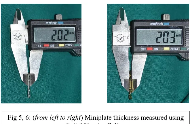
iv. All the plates were measured for dimensions and profile changes prior to and after bending and twisting using digital Vernier Calliper and Precision Vision Measuring System (VMS) RAPID-I.
v. Initially a 3D model of mandible with simulated fractures at the symphysis region and angle region was created, 2.0mm Conventional & Locking Titanium straight 4-hole with gap miniplates & screws post bending were created and all the plates were adapted in place of the fracture site and 8 individual fracture simulated models were created using part modelling software i.e., CATIA V5.
vi. Components and mandible were saved in IGES format.
vii. The same model was imported to the HyperMesh, pre-processor software, for meshing and applying boundary and load conditions.
32
[image:44.595.103.533.182.654.2]MATERIALS AND METHODS:
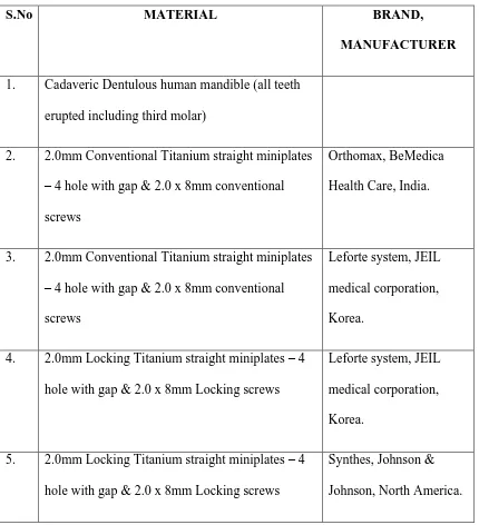
TABLE 1: MATERIALS
S.No MATERIAL BRAND,
MANUFACTURER
1. Cadaveric Dentulous human mandible (all teeth erupted including third molar)
2. 2.0mm Conventional Titanium straight miniplates – 4 hole with gap & 2.0 x 8mm conventional screws
Orthomax, BeMedica Health Care, India.
3. 2.0mm Conventional Titanium straight miniplates – 4 hole with gap & 2.0 x 8mm conventional screws
Leforte system, JEIL medical corporation, Korea.
4. 2.0mm Locking Titanium straight miniplates – 4 hole with gap & 2.0 x 8mm Locking screws
Leforte system, JEIL medical corporation, Korea.
5. 2.0mm Locking Titanium straight miniplates – 4 hole with gap & 2.0 x 8mm Locking screws
33
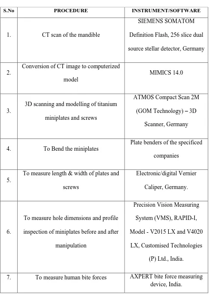
TABLE 2: EQUIPMENTS
S.No PROCEDURE INSTRUMENT/SOFTWARE
1. CT scan of the mandible
SIEMENS SOMATOM Definition Flash, 256 slice dual source stellar detector, Germany
2.
Conversion of CT image to computerized model
MIMICS 14.0
3.
3D scanning and modelling of titanium miniplates and screws
ATMOS Compact Scan 2M (GOM Technology) – 3D
Scanner, Germany
4. To Bend the miniplates
Plate benders of the specificed companies
5.
To measure length & width of plates and screws
Electronic/digital Vernier Caliper, Germany.
6.
To measure hole dimensions and profile inspection of miniplates before and after
manipulation
Precision Vision Measuring System (VMS), RAPID-I, Model - V2015 LX and V4020
LX, Customised Technologies (P) Ltd., India.
34
TABLE 3: SOFTWARE
S.No PROCEDURE SOFTWARE MANUFACTURER
1. CAD modelling CATIA V5 Dassault systemes,
Velizy Villacoublay,
France.
2. Finite element modelling Altair hypermesh Altair engineering Inc., Michigan,
USA.
3. Meshing Shell 181 Ansys Inc.,
Pennsylvania, USA.
4. Analysis Ansys 14.5 Ansys Inc.,
35
SCHEMA OF THE STUDY
Selection of a human cadaveric mandible dentulous with the presence of third molars.
CT scan of the mandible was done with 3D reconstruction using MIMICS software.
3D Scanning before and after bending of miniplates using their manufacturer specified plate benders.
Dimensions and profile changes prior to and after bending and twisting using digital Vernier Calliper and Precision Vision Measuring System(VMS), RAPID-I
8 individual fracture models fixed with miniplates were created using Part Modelling software – CATIA V5
Finite Element Modelling in Hypermesh
Meshing in SHELL 181
36
1) Selection of Cadaveric human mandible and 3D reconstruction of the model with CT data.
Cadaveric human mandible with all the teeth erupted including the third molars in the arch was taken for the study and CT scanning of the mandible done. 3D reconstruction of the mandible was achieved using MIMICS software. Ethical clearance was obtained.
2) Miniplates 3D scanning and measurements
2.0mm conventional and locking titanium miniplates and conventional and locking head screws of different designs were measured prior to and after bending using digital Vernier Caliper and VMS – RAPID-I. All the plates were bent by single operator for standardization. Four miniplates for each plate designs were taken into consideration and two plates for symphysis region and one for the angle region was bent and adapted. After which the miniplates were placed under 3D ATMOS scanner and all the components were scanned for adaptation to the fracture simulated mandibular 3D model.
3) CAD Modelling
37
Steps for creating the model
i. Initially a 2D sketch of the mandible was created using profile toolbar which is used to create simple geometries.
ii. Dimensions and constraints are given to the sketch to restrict its degrees of freedom and make it stable.
iii. The 2D sketch was then converted into 3D model by using an option called rib.
4) Finite element model
CAD model was then imported to a meshing software tool to generate mesh. The final meshed model consists of several elements that collectively represent the entire structure. The elements not only represent segments of the structure, they also simulate it’s mechanical behavior and properties. Meshing of the Mandibular structure is done in Altair HyperMesh V11.
Material properties
38
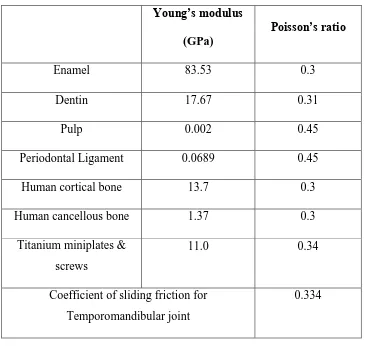
Table 4: Material properties
Young’s modulus
(GPa)
Poisson’s ratio
Enamel 83.53 0.3
Dentin 17.67 0.31
Pulp 0.002 0.45
Periodontal Ligament 0.0689 0.45
Human cortical bone 13.7 0.3
Human cancellous bone 1.37 0.3
Titanium miniplates & screws
11.0 0.34
Coefficient of sliding friction for Temporomandibular joint
0.334
5) Application of boundary conditions and pressure
39
Applying pressure: The total force acting was applied on the occlusal surface of the dentulous mandible.
6) Force Values for different clinical conditions
As 2 different clinical conditions (symphysis & angle fracture) are considered in this study, different areas where forces applied are:
1) For right angle fracture forces are applied over right molars, right premolars & right anteriors.
2) For symphysis fracture forces applied over bilateral molars and premolars.
This is used to evaluate the Von Mises stress over the plates and the adjacent bone over FEA model. The forces of occlusion to be evaluated were determined from various sources of literature.
40
TABLE 5: Statistical Average Bite forces obtained from 2months post operated group
TOOTH VALUE (Kg) (Average) VALUE (N) (Average)
RIGHT MOLAR 22.65273 226.5293
RIGHT PREMOLAR 19.76127 197.6127
ANTERIORS 13.72393 137.2393
LEFT PREMOLAR 22.45033 224.5033
LEFT MOLAR 25.61767 256.1767
41
TABLE 6: NUMERIC PAIN RATING SCALE – PRE OPERATIVE
S.No PATIENT NAME AGE SEX 0 1 2 3 4 5 6 7 8 9 10
1 JAGADEESH 26 M X
2 VELUSAMY 50 M X
3 GOWTHAMAN 22 M X
4 KANAGARAJ 30 M X
5 KAMESH 21 M X
6 SUNDAR 30 M X
7 SAMPATH KUMAR 26 M X
8 PALANISAMY 26 M X
9 RAVI 33 M X
10 RAGHUVEER 24 M X
11 SENTHIL KUMAR 46 M X
12 SANTOSH 28 M X
13 SATISH KUMAR 24 M X
14 DAVID 19 M X
15 SAKTHIVEL 25 M X
16 VIJAYARAGHAVAN 34 M X
17 DHANASEKAR 20 M X
18 MURUGAN 48 M X
19 AVINASH 23 M X
20 RAVICHANDRAN 43 M X
X – PAIN SUFFERED BY THE PATIENT
42
TABLE 7: NUMERIC PAIN RATING SCALE – 1 WEEK POST OPERATIVE
S.No PATIENT NAME AGE SEX 0 1 2 3 4 5 6 7 8 9 10
1 JAGADEESH 26 M X
2 VELUSAMY 50 M X
3 GOWTHAMAN 22 M X
4 KANAGARAJ 30 M X
5 KAMESH 21 M X
6 SUNDAR 30 M X
7 SAMPATH KUMAR 26 M X
8 PALANISAMY 26 M X
9 RAVI 33 M X
10 RAGHUVEER 24 M X
11 SENTHIL KUMAR 46 M X
12 SANTOSH 28 M X
13 SATISH KUMAR 24 M X
14 DAVID 19 M X
15 SAKTHIVEL 25 M X
16 VIJAYARAGHAVAN 34 M X
17 DHANASEKAR 20 M X
18 MURUGAN 48 M X
19 AVINASH 23 M X
20 RAVICHANDRAN 43 M X
X – PAIN SUFFERED BY THE PATIENT
43
TABLE 8: NUMERIC PAIN RATING SCALE – 1 MONTH POST OPERATIVE
S.No PATIENT NAME AGE SEX 0 1 2 3 4 5 6 7 8 9 10
1 JAGADEESH 26 M X
2 VELUSAMY 50 M X
3 GOWTHAMAN 22 M X
4 KANAGARAJ 30 M X
5 KAMESH 21 M X
6 SUNDAR 30 M X
7 SAMPATH KUMAR 26 M X
8 PALANISAMY 26 M X
9 RAVI 33 M X
10 RAGHUVEER 24 M X
11 SENTHIL KUMAR 46 M - - - -
12 SANTOSH 28 M X
13 SATISH KUMAR 24 M X
14 DAVID 19 M X
15 SAKTHIVEL 25 M X
16 VIJAYARAGHAVAN 34 M X
17 DHANASEKAR 20 M X
18 MURUGAN 48 M X
19 AVINASH 23 M X
20 RAVICHANDRAN 43 M X
X – PAIN SUFFERED BY THE PATIENT
44
TABLE 9: NUMERIC PAIN RATING SCALE – 2 MONTHS POST OPERATIVE
S.No PATIENT NAME AGE SEX 0 1 2 3 4 5 6 7 8 9 10
1 JAGADEESH 26 M X
2 VELUSAMY 50 M X
3 GOWTHAMAN 22 M X
4 KANAGARAJ 30 M X
5 KAMESH 21 M X
6 SUNDAR 30 M X
7 SAMPATH KUMAR 26 M X
8 PALANISAMY 26 M X
9 RAVI 33 M X
10 RAGHUVEER 24 M X
11 SENTHIL KUMAR 46 M - - - -
12 SANTOSH 28 M X
13 SATISH KUMAR 24 M X
14 DAVID 19 M X
15 SAKTHIVEL 25 M X
16 VIJAYARAGHAVAN 34 M X
17 DHANASEKAR 20 M - - - -
18 MURUGAN 48 M - - - -
19 AVINASH 23 M - - - -
20 RAVICHANDRAN 43 M - - - -
X – PAIN SUFFERED BY THE PATIENT
45 7) Analysis
In this step the finite element model was exported to the solver software to carry out analysis. Both solving and post processing of fracture simulated mandibular model was done in Ansys V14.5.
Post processing
This is the final step in a finite element analysis. Results obtained in the
previous phase are usually in the form of raw data and difficult to interpret. In post
analysis, a CAD program was utilized to manipulate the data for generating deflected
shape of the structure, creating stress plots, animation, etc. A graphical representation
of the results is very useful in understanding the behaviour of a structure. The results
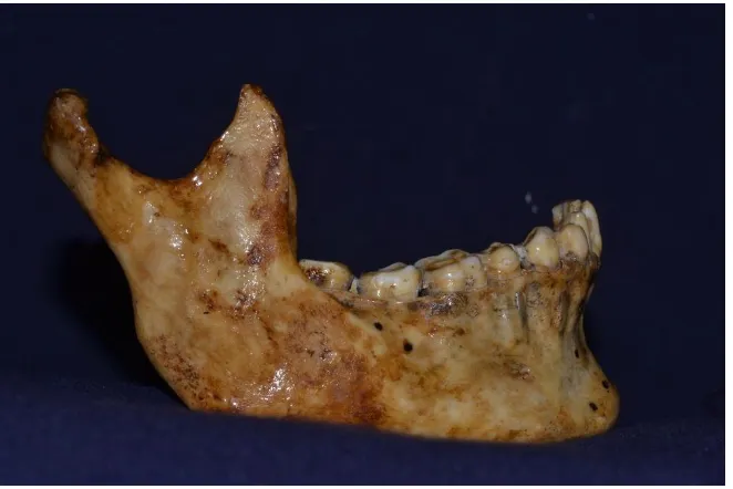
[image:58.595.180.511.139.360.2]
Fig 1: Cadaveric dentulous human mandible with all teeth including third molar present
[image:58.595.127.520.446.691.2]
Fig 5, 6: (from left to right) Miniplate thickness measured using digital Vernier Caliper
4A ) )
4B ) )
[image:59.595.151.542.162.463.2]4C 4D
[image:59.595.182.512.514.730.2]
Fig 9, 10: (from left to right) Original plate before bending and dimensional change shown after bending
Fig 13, 14: (from left to right) Meshed Titanium miniplate and mandible model with simulated fracture depicted in different colours
1 2 3 4
Figure 16: From right to left number of the hole marked and the dimensional change is checked under RAPID – I, both for tension and
compression border plates in symphysis fracture.
Figure 17: From top to bottom number of the hole marked and the dimensional change is checked under RAPID – I for angle fracture.
1
2
3
RAPID – I – VMS MEASUREMENTS
NORMAL PROFILE AND MEASUREMENTS - ORTHOMAX CONVENTIONAL PLATES
ORTHOMAX CONVENTIONAL PLATES - SYMPHYSIS REGION: TENSION BORDER
Figure 18: Profile of Orthomax Conventional Plate
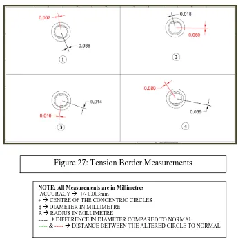
NOTE: All Measurements are in Millimetres
ACCURACY +/- 0.003mm
+ CENTRE OF THE CONCENTRIC CIRCLES
DIAMETER IN MILLIMETRE
R RADIUS IN MILLIMETRE
--- DIFFERENCE IN DIAMETER COMPARED TO NORMAL
--- & --- DISTANCE BETWEEN THE ALTERED CIRCLE TO NORMAL
COMPRESSION BORDER
ORTHOMAX CONVENTIONAL PLATES – ANGLE REGION:
NOTE: All Measurements are in Millimetres
ACCURACY +/- 0.003mm
+ CENTRE OF THE CONCENTRIC CIRCLES
DIAMETER IN MILLIMETRE
R RADIUS IN MILLIMETRE
--- DIFFERENCE IN DIAMETER COMPARED TO NORMAL
--- & --- DISTANCE BETWEEN THE ALTERED CIRCLE TO NORMAL
Figure 20: Compression Border Measurements
NORMAL PROFILE AND MEASUREMENTS - LEFORTE CONVENTIONAL PLATE
LEFORTE CONVENTIONAL PLATES – SYMPHYSIS REGION:
TENSION BORDER
NOTE: All Measurements are in Millimetres
ACCURACY +/- 0.003mm
+ CENTRE OF THE CONCENTRIC CIRCLES
DIAMETER IN MILLIMETRE
R RADIUS IN MILLIMETRE
--- DIFFERENCE IN DIAMETER COMPARED TO NORMAL
[image:66.595.182.493.94.302.2]--- & --- DISTANCE BETWEEN THE ALTERED CIRCLE TO NORMAL
[image:66.595.181.536.394.749.2]COMPRESSION BORDER
LEFORTE CONVENTIONAL PLATES – ANGLE REGION:
NOTE: All Measurements are in Millimetres
ACCURACY +/- 0.003mm
+ CENTRE OF THE CONCENTRIC CIRCLES
DIAMETER IN MILLIMETRE
R RADIUS IN MILLIMETRE
--- DIFFERENCE IN DIAMETER COMPARED TO NORMAL
[image:67.595.136.512.104.796.2]--- & --- DISTANCE BETWEEN THE ALTERED CIRCLE TO NORMAL
Figure 24: Compression Border Measurements
NORMAL PROFILE AND MEASUREMENTS – LEFORTE LOCKING PLATES
LEFORTE LOCKING PLATES – SYMPHYSIS REGION:
TENSION BORDER
NOTE: All Measurements are in Millimetres
ACCURACY +/- 0.003mm
+ CENTRE OF THE CONCENTRIC CIRCLES
DIAMETER IN MILLIMETRE
R RADIUS IN MILLIMETRE
--- DIFFERENCE IN DIAMETER COMPARED TO NORMAL
[image:68.595.165.504.139.381.2]--- & --- DISTANCE BETWEEN THE ALTERED CIRCLE TO NORMAL
Figure 26: Profile of Leforte Locking Plate
[image:68.595.161.506.439.783.2]COMPRESSION BORDER
LEFORTE LOCKING PLATE – ANGLE REGION:
NOTE: All Measurements are in Millimetres
ACCURACY +/- 0.003mm
+ CENTRE OF THE CONCENTRIC CIRCLES
DIAMETER IN MILLIMETRE
R RADIUS IN MILLIMETRE
--- DIFFERENCE IN DIAMETER COMPARED TO NORMAL
[image:69.595.183.527.134.382.2]--- & --- DISTANCE BETWEEN THE ALTERED CIRCLE TO NORMAL
[image:69.595.163.531.139.609.2]Figure 29: Angle Region Plate Measurements
NORMAL PROFILE AND MEASUREMENTS – SYNTHES LOCKING PLATES
[image:70.595.168.507.141.740.2]
Figure 30: Profile of Synthes Locking Plate
NOTE: All Measurements are in Millimetres
ACCURACY +/- 0.003mm
+ CENTRE OF THE CONCENTRIC CIRCLES
DIAMETER IN MILLIMETRE
R RADIUS IN MILLIMETRE
--- DIFFERENCE IN DIAMETER COMPARED TO NORMAL
SYNTHES LOCKING PLATES – SYMPHYSIS REGION: TENSION BORDER
COMPRESSION BORDER
NOTE: All Measurements are in Millimetres
ACCURACY +/- 0.003mm
+ CENTRE OF THE CONCENTRIC CIRCLES
DIAMETER IN MILLIMETRE
R RADIUS IN MILLIMETRE
--- DIFFERENCE IN DIAMETER COMPARED TO NORMAL
[image:71.595.140.504.122.489.2]--- & --- DISTANCE BETWEEN THE ALTERED CIRCLE TO NORMAL
Figure 31: Tension Border Measurements
[image:71.595.141.514.254.759.2]SYNTHES LOCKING PLATES – ANGLE REGION:
NOTE: All Measurements are in Millimetres
ACCURACY +/- 0.003mm
+ CENTRE OF THE CONCENTRIC CIRCLES
DIAMETER IN MILLIMETRE
R RADIUS IN MILLIMETRE
--- DIFFERENCE IN DIAMETER COMPARED TO NORMAL
[image:72.595.146.493.206.553.2]--- & --- DISTANCE BETWEEN THE ALTERED CIRCLE TO NORMAL
46
The evaluation of the Finite Element Analysis results was performed with respect to displacement and stresses in the titanium miniplates. One of the main parameters for different fracture stabilization alternatives is the fracture mobility. It is an indication of rigidity of the fixation of the 2 fractured segments of the mandible, appropriate osteogenesis and bone healing. The load across the fracture resulted in mobility of the fragments and displacement in the x, y, and z directions (Figure-34). Considering that, displacement was calculated by vectorial summarization of the movements in the x, y, and z directions. The displacement measurements for all models are presented.
The analysis was done to determine the stress over the plate & bone on vertical load application and also to determine the deformation (strain) of the bone and development of fracture gap in relation to the loading conditions. The loads were applied to simulate patients with opposing maxillary natural dentition. All stress values are given in MPa (N/mm2).
The vertical loading forces (bite forces) cause tensile stresses in the alveolar area and compression stresses in the basal mandibular area. In the control model, the stress distribution was high in the symphysis region. With complete load, symphysis fracture gap was opened and the pressure stress got increased. With segmental load angle fracture gap was opened and the pressure stress got increased.
47
The results were analysed for the following factors:
1) Deflection & stability 2) Mechanical stress over bone
3) Maximal stress area over miniplates 4) Fracture gap and
48
LOADS AND BOUNDARY CONDITIONS
Figure 36: FORCES APPLIED FOR SYMPHYSIS FRACTURE Figure 35: FORCES APPLIED FOR
[image:76.595.90.544.93.730.2]ANGLE FRACTURE
49 TABLE 10: MAXIMUM DEFLECTION
S.No. FRACTURE FIXATION MODEL MAXIMUM
DEFLECTION (mm) 1 Orthomax conventional plate in symphysis
region
6.05196
2 Orthomax conventional plate in angle region
5.93459
3 Leforte conventional plate in symphysis region
4.85454
50
TABLE 11: MAXIMUM MECHANICAL STRESS OVER BONE
S.No. FRACTURE FIXATION MODEL MAXIMUM STRESS
OVER BONE (MPa) 1 Orthomax conventional plate in symphysis
region
98.6537
2 Orthomax conventional plate in angle region
379.81
3 Leforte conventional plate in symphysis region
92.5581
4 Leforte conventional plate in angle region 292.046
5 Leforte locking plate in symphysis region 288.611
6 Leforte locking plate in angle region 449.205
7 Synthes locking plate in symphysis region 78.476
8 Synthes locking plate in angle region 309. 63
51
TABLE 12: MAXIMAL STRESS OVER MINIPLATES
S.No. FRACTURE FIXATION MODEL
MAXIMAL STRESS OVER MINIPLATES
(MPa) 1 Orthomax conventional plate in symphysis
region
75.4011
2 Orthomax conventional plate in angle region 2114.62
3 Leforte conventional plate in symphysis region
67.9809
4 Leforte conventional plate in angle region 1145.38
5 Leforte locking plate in symphysis region 73.3317
6 Leforte locking plate in angle region 1540.14
7 Synthes locking plate in symphysis region 61.2447
52 TABLE 13: FRACTURE GAP
S.No. FRACTURE FIXATION MODEL FRACTURE GAP
(mm) 1 Orthomax conventional plate in symphysis
region
0.86241
2 Orthomax conventional plate in angle region
2.2708
3 Leforte conventional plate in symphysis region
0.09959
4 Leforte conventional plate in angle region 1.295088
5 Leforte locking plate in symphysis region 0.01804
6 Leforte locking plate in angle region 1.86241
7 Synthes locking plate in symphysis region 0.088748
8 Synthes locking plate in angle region 1.18295
53
TABLE 14: DIRECTION OF DISPLACEMENT
S.No. FRACTURE FIXATION MODEL
DIRECTION OF DISPLACEMENT OF
FRACTURED SEGMENTS 1 Orthomax conventional plate in symphysis
region
Lateral
2 Orthomax conventional plate in angle region
Medial
3 Leforte conventional plate in symphysis region
Lateral
4 Leforte conventional plate in angle region Medial
5 Leforte locking plate in symphysis region Lateral
6 Leforte locking plate in angle region Medial
7 Synthes locking plate in symphysis region Lateral
SYMPHYSIS FRACTURE FIXATION
SYNTHES LOCKING PLATES:
[image:82.595.146.520.274.604.2]Maximum deflection on application of bilateral vertical loads is 6.07613 mm. While the Von Mises Stress over miniplates are 61.2447 MPa and over bone near the screwed area is 78.476 MPa.
LEFORTE LOCKING PLATES:
[image:83.595.149.538.240.565.2]Maximum deflection on application of bilateral vertical loads is 2.50747mm. While the Von Mises Stress over miniplates are 73.3317 MPa and over bone near the screwed area is 288.611 MPa.
LEFORTE CONVENTIONAL PLATES:
[image:84.595.147.534.285.596.2]Maximum deflection on application of bilateral vertical loads is 4.85454 mm. While the Von Mises Stress over miniplates are 67.9809 MPa and over bone near the screwed area is 92.5581 MPa.
ORTHOMAX CONVENTIONAL PLATES:
[image:85.595.146.535.259.559.2]Maximum deflection on application of bilateral vertical loads is 6.05196mm. While the Von Mises Stress over miniplates are 75.4011 MPa and over bone near the screwed area is 98.6537 MPa.
ANGLE FRACTURE FIXATION
SYNTHES LOCKING PLATES:
[image:86.595.149.544.262.599.2]Maximum deflection on application of bilateral vertical loads is 3.00287 mm. While the Von Mises Stress over the miniplate is 833.457 MPa and over bone near the screwed area is 309.63 MPa.
LEFORTE LOCKING PLATES:
[image:87.595.148.544.219.526.2]Maximum deflection on application of bilateral vertical loads is 3.45596 mm. While the Von Mises Stress over the miniplate is 1540.14 MPa and over bone near the screwed area is 449.205 MPa.
LEFORTE CONVENTIONAL PLATES:
[image:88.595.146.542.258.588.2]Maximum deflection on application of bilateral vertical loads is 2.42414 mm. While the Von Mises Stress over the miniplate is 1145.38 MPa and over bone near the screwed area is 292.046 MPa.
ORTHOMAX CONVENTIONAL PLATES:
Maximum deflection on application of bilateral vertical loads is 5.93459 mm. While the Von Mises Stress over the miniplate is 2114.62 MPa and over bone near the screwed area is 379.81 MPa.
54
RESULT INFERENCE:
Symphysis fracture fixation showed maximum deflection with Orthomax conventional and least with Leforte locking plates. Maximum stress over bone and plate was observed in Orthomax conventional and least with Synthes locking. Fracture gap was more in Orthomax conventional and least with Leforte locking. So the more stable plate is Synthes locking plate followed by Leforte locking plate.
Angle fracture fixation showed maximum deflection with Orthomax conventional and least with Synthes locking plates. Maximum stress over bone was with Orthomax conventional and least in Synthes locking plates. But stress over plate was more in Leforte conventional and least in Synthes locking. Fracture gap was more in Orthomax conventional and least with Leforte locking. So the more stable plate is Synthes locking plate followed by Leforte locking plate.
55
Normal mandible is subjected to bending forces in the upper border & to compression forces in the lower border.1,2,3,4 In angle and symphysis fracture, torsional forces act in the angle region and tension forces are more concentrated in the symphyseal region.10,11,12 Symphysis & angle fractures are 2nd most common fractures after condylar fractures. 11,17,28,29 The three main principles of fracture