EVALUATION
A thesis presented in partial fulfilment of the requirements for the degree of
Master of Engineering
In
Mechatronics
at
Massey University,
Palmerston North, New Zealand
Darren Lewis
Abstract
The aim of this masters project was to design and develop a prototype of robotic chewing device. This project was required for use in food evaluation as it can provide standardised chewing. The chewing device was required to follow chewing trajectories of a human and apply the same forces that humans apply during chewing. This was achieved by the use of a robotic system that incorporated a mechanical linkage, supporting software and electronics to control it and therefore ensure correct operation. The mechanical linkage used is based on a four-bar linkage mechanism that can closely approximate human chewing trajectories. The linkage also has the ability to be adjusted to achieve a range of chewing trajectories for different food types. This is due to the fact that humans chew foods with different properties differently. The linkage is driven by a single DC motor that is controlled by a control card and a supervisory software program on a computer. This ensures that chewing is performed at the correct speed in the different phases of the chewing cycle and also provides all the necessary controls for operation of the device. Anatomically correct teeth were also used to help closely match the particle size reduction of the human system, while a food retention device was made to keep the food particles on the teeth while chewing.
-Acknowledgements
I would first of all like to thank my supervisors Dr. John Bronlund, Assoc. Prof. Peter Xu and Dr. Kylie Foster who have guided me throughout this project and help make it a success.
The technicians at the Massey University Institute of Technology and Engineering workshop for their help and support.
Christine Lawrence from Massey University Auckland for her help.
Prof. Jules Kieser, lonut lchim and Neil Waddell from the School of Dentistry at the University of Otago for their guidance on the function of teeth.
Flanders, Sebastian, Jonathan for their help and friendliness throughout the year.
And finally Crop and Food New Zealand for funding this project.
-Table of contents
LIST OF FIGURES ...... 9
LIST OF TABLES ... 13
1 INTRODUCTION ................ 15
2 LITERATURE REVIEW ...... 17
2.1 INTRODUCTION ... 17
2.2 HUMAN MASTICATORY SYSTEM ... 17
2.2. 1 Overview ...................... 17
2.2.2 Jaw geometry ... 19
2.2.3 Teeth shape ................................ 21
2.2. 4 Forces on teeth ..... 23
2.2.5 Jaw trajectories during chewing ....................................... 23
2.3 CONCLUSION ... 30
3 POSSIBLE DESIGN APPROACHES .................. 33
3.1 INTRODUCTION ... 33
3.2 THE FOUR-BAR LINKAGE ... 33
3.3 CAM TRAJECTORY SYSTEM ... 34
3.4 TWO-AXIS TRAJECTORY SYSTEM ... 36
3.5 PLATFORM ROBOT ... 36
3.6 ROBOTIC SYSTEM EVALUATION ... 37
4 FOUR-BAR LINKAGE MECHANISM DESIGN ......... 39
4.1 INTRODUCTION ... 39
4.2 SPECIFICATIONS ... 39
4.3 LINKAGE DESIGN ... 39
4.3. 1 Constraints .................... 39
4.3.2 Design approaches ... .40
4.3.3 The four-bar design ................................................ 42
4.4 MECHANICAL DESIGN ... 50
4.4. 1 The basic mechanical design ... 50
4.4.2 The six-bar linkage design ................................... 52
4.4.3 Stress analysis ............................... 54
4.4.4 Six-bar linkage kinematics ............................................. 56
4.4.5 Six-bar linkage dynamics ............. 63
4.5 MOTOR SELECTION ... 69
4.6 CONSTRUCTION ... 73
4.7 RESULTS ... 73
4.7.1 Force measurement .... 74
4. 7.2 Trajectory measurement ................................... 76
4.8 CONCLUSIONS ... 77
5 SUPPORTING DESIGN ........... 79
5. 1 INTRODUCTION ... 79
5.2 THE FORCE CONTROL ... 79
5.3 THE CHEWING DEVICE ENCLOSURE ... 86
5.4 THE TEETH LOCKING MECHANISMS ... 88
5.4. 1 The lower teeth locking mechanism ............. 89
5.4.2 The upper teeth locking mechanism ... 90
5.5 TEETH, FOOD RETENTION AND REPOSJTIONING ... 92
5. 5. 1 The teeth ... 92
-A Robotic Chewing Device for Food Evaluation
5.5.2 The food retention system ... 93
5.5.3 The food repositioning system ...... 94
5.6 CONSTRUCTION ... 94
5. 7 CONCLUSIONS ... 99
6 CONTROL ................................................................. 101
6.1 INTRODUCTION ... 101
6.2 COMPUTER/MOTOR INTERFACE ... 101
6.2.1 The control card ... 101
6.2.2 The line driver circuit ............................. 102
6.2.3 Computer I/O ... 103
6.3 THE SOFTWARE FUNCTIONS ... 104 6. 3. 1 Set to lower position ........................ 105
6.3.2 Set to top position ......................................... 108
6.3.3 Start chewing ........................................... 108
6.3.4 Single cycle ... 116 6.3.5 Low speed manual control ..................... 117
6.3.6 Master stop ... 118
6.4 CONCLUSIONS ... 119
7 CONCLUSIONS AND FUTURE WORK ...................................................... 121
8 REFERENCES ................................................................. 125
9 APPENDIX A THE INSTRUCTION MANUAL. .................................................. 129
10 APPENDICES B-E ....... 137 10. 1 APPENDIX BC.A. D FILES ... 137 10.2 APPENDIX C LABVIEW FILES ... 137 10.3 APPENDIX D CONTROL CARD FILES ... 137
List of figures
Figure 2-1 The location of muscles that are used in chewing (adapted from Hannam
1997) ... 18
Figure 2-2 The human mandible (adapted from Gray 1918) ... 20
Figure 2-3 The curve of Wilson and the curve of Spee (taken from Palmer 2004) ... 20
Figure 2-4 Teeth in the human mouth (taken from Oralb) ... 21
Figure 2-5 Three point bending principle adapted to mastication for fracturing food (adapted from Ashby & Jones 1996) ... 22
Figure 2-6 The masticatory sequence (taken from Lucas 2004b) ... 24
Figure 2-7 Frontal and sagittal trajectories of a typical adult when chewing soft cheese on the right side (taken from Gibbs & Lundeen 1982) ... 25
Figure 2-8 Sagittal and frontal trajectories of a typical adult when chewing carrot (taken from Gibbs & Lundeen 1982) ... 25
Figure 2-9 Average frontal and sagittal trajectories for a typical adult when chewing hard and soft gum (adapted from Anderson et al, 2002) ... 26
Figure 2-10 The decision of what teeth function to use (adapted from Lucas 2004c) .. 27
Figure 2-11 J.-S. Pap's SolidWorks model ... 28
Figure 2-12 Comparison between first molar and incisor chewing trajectories ... 29
Figure 3-1 The four-bar linkage (adapted from Thompson 1999a) ... 33
Figure 3-2 The cam follower system (adapted from University of Limerick) ... 34
Figure 3-3 VTEC system at low revs (taken from Honda marine) ... 35
Figure 3-4 VTEC system at high revs (taken from Honda marine) ... 35
Figure 3-5 A hexapod platform robot (taken from Physic lnstrumente 1996-2005) ... 37
Figure 4-1 Limit and dead configurations of a four-bar linkage (taken from Stanisic) ... 41
Figure 4-2 The maximum and minimum transmission angles (taken from Stanisic) ... 42
Figure 4-3 The four-bar linkage parameters (taken from Thompson 1999a) ... 42
Figure 4-4 Candidate trajectories of the four-bar linkage (adapted from Thompson 1999b) ... 43
Figure 4-5 Candidate trajectories when the ground length is reduced (adapted from Thompson 1999b) ... 44
Figure 4-6 Simple model to evaluate different link lengths ... 45
Figure 4-7 Definition of parameters in Table 4 ... 46
Figure 4-8 Sample trajectories that the four-bar linkage can achieve ... 47
-A Robotic Chewing Device for Food Evaluation
Figure 4-9 Vertical trajectory as a function of crank angle with a 50mm ground ... 48
Figure 4-10 Horizontal trajectory as a function of crank angle with a 50mm ground .... .48
Figure 4-11 Transmission angle when ground length is 50mm ... 49
Figure 4-12 Transmission angle when ground length is 38mm ... .49
Figure 4-13 The ground link ... 50
Figure 4-14 The basic design of the four-bar linkage ... 51
Figure 4-15 The assembly of the four-bar linkage ... 52
Figure 4-16 The six-bar linkage ... 53
Figure 4-17 The final six bar linkage design ... 54
Figure 4-18 The stress analysis of the four-bar linkage ... 55
Figure 4-19 The deflection analysis of the four-bar linkage ... 56
Figure 4-20 The co-ordinate system for the kinematics ... 57
Figure 4-21 The angular displacement of the follower ... 58
Figure 4-22 The angular velocity of the follower ... 58
Figure 4-23 The angular acceleration of the follower. ... 58
Figure 4-24 The linear displacement of the slider in the 'X' direction ... 59
Figure 4-25 The linear displacement of the slider in the 'Y' direction ... 59
Figure 4-26 The linear displacement of the slider in the 'Z' direction ... 60
Figure 4-27 The velocity of the slider in the 'X' direction ... 60
Figure 4-28 The velocity of the slider in the 'Y' direction ... 61
Figure 4-29 The velocity of the slider in the 'Z' direction ... 61
Figure 4-30 The acceleration of the slider in the 'X' direction ... 62
Figure 4-31 The acceleration of the slider in the 'Y' direction ... 62
Figure 4-32 The acceleration of the slider in the 'Z' direction ... 62
Figure 4-33 The joints of interest in the dynamic analysis ... 63
Figure 4-34 The crank torque of the six-bar linkage ... 64
Figure 4-35 'X' direction force in crank-coupler joint. ... 64
Figure 4-36 'Y' direction force in crank-coupler joint.. ... 65
Figure 4-37'X' direction force in follower-ground joint.. ... 66
Figure 4-38 'Y' direction force in follower-ground joint.. ... 66
Figure 4-39'X' direction force in follower-coupler joint ... 67
Figure 4-40 'Y' direction force in follower-coupler joint ... 67
Figure 4-41 'X' direction force in crank-ground joint ... 68
Figure 4-42 'Y' direction force in crank-ground joint ... 68
Figure 4-44 The weight concentration of the linkage ... 71
Figure 4-45 The location of the motor and the drive line ... 72
Figure 4-46 The six-bar linkage constructed ... 73
Figure 4-47 The force measuring device ... 75
Figure 4-48 Sample of force measuring program ... 76
Figure 4-49 The overlay comparing the achieved trajectory and desired trajectories ... 77
Figure 5-1 The location of the shock absorber ... 81
Figure 5-2 The vertical velocity of the actuator ... 83
Figure 5-3 The response of the shock absorber when compressed at different velocities ... 83
Figure 5-4 The vertical acceleration of the actuator ... 85
Figure 5-5 The force response of the shock absorber ... 86
Figure 5-6 The enclosure of the chewing device ... 88
Figure 5-7 Exploded view of lower teeth locking mechanism ... 89
Figure 5-8 The upper teeth locking mechanism ... 90
Figure 5-9 The enclosure showing the location of the six-bar linkage and the teeth locking mechanisms ... 91
Figure 5-10 The plaster moulds of the upper and lower jaws ... 93
Figure 5-11 The final resin mould of the upper jaw with the teeth in place ... 93
Figure 5-12 The food retention system ... 94
Figure 5-13 The chewing device enclosure ... 95
Figure 5-14 The six-bar linkage ... 96
Figure 5-15 The upper teeth locking mechanism ... 96
Figure 5-16 The lower teeth locking mechanism ... 96
Figure 5-17 The final assembled SolidWorks model of the chewing device ... 97
Figure 5-18 The constructed chewing device ... 98
Figure 6-1 The line driver circuit showing the line driver chip in the centre and the connectors on either side ... 103
Figure 6-2 The circuit board design (Board dimensions 22x15mm) ... 103
Figure 6-3 The software functions on the GUI ... 105
Figure 6-4 The Hall Effect sensing circuit ... 106
Figure 6-5 The Hall Effect circuit board ... 106
Figure 6-6 Example of accessing the parallel port in Labview ... 107
Figure 6-7 The general velocity profile of the chewing device ... 109
Figure 6-8 The occlusal phase definition ... 110
-A Robotic Chewing Device for Food Evaluation
Figure 6-9 The trajectory profile ... 112
Figure 6-1 O The velocity profile ... 112
Figure 6-11 The acceleration profile ... 113
Figure 6-12 The occlusal angle ... 114
Figure 6-13 The velocity control menu ... 116
Figure 6-14 The 'single cycle' Labview code ... 117
Figure 6-15 The 'low speed manual control' function ... 118
List of tables
Table 1 Movement variables for vertical and horizontal chewing motions (adapted from
Ogawa et al. 2001) ...... 29
Table 2 Frontal trajectory properties (adapted from Ogawa et al 2001) ... 31
Table 3 Evaluation of the different possible robotic systems ... 38 Table 4 Comparison between the designed four-bar linkage and the experimental data
(adapted from Ogawa et al, 2004) ... 46
Table 5 Comparison of required and achievable specifications ... 73
-1 Introduction
The aim of this thesis research was to design and implement a robotic chewing device
for the evaluation of foods. This required the device to approximate the human chewing
cycle. To do so, extensive research was carried out in order to understand how humans
chew and the important features that prepare the bolus for swallowing. Once this was
done, a mechanical system could be built and controlled to ensure correct operation.
The specific aspects of the food chewing of interest are the grinding of the food sample
to form a bolus ready for swallowing. Ideally the robotically chewed bolus would have
similar particle size distributions and rheology to human chewed samples.
The tasks of the thesis were identified to be:
• Research the human chewing motion and identify the important aspects of jaw
movement that prepare the bolus for swallowing
• Analyse and design a mechanism that is able to reproduce the key aspects of
the human masticatory cycle
• Construct the designed mechanism
• Implement a suitable controller for controlling the mechanism
-2 Literature review
2.1 Introduction
The literature reviewed in this chapter is to study the operation of the human chewing
cycle. This is required to specify the requirements of the chewing device and what
important factors need to be considered to ensure that the chewed food sample that the
chewing device provides is similar to that of what a human produces.
2.2 Human masticatory system
2.2.1 Overview
The human masticatory system is a complex system that comprises of an upper and
lower jaw that have teeth located on them. It also includes a tongue, check and saliva
production capability. When mastication is performed, the lower jaw is moved by
muscles that are attached between it and the upper jaw. These muscles are
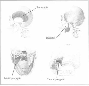
responsible for the chewing motion can be broken up into five main muscle groups
which are as follows; (Lucas 2004, A)
•
The temporalis•
The masseter•
The medial pterygoid•
The lateral pterygoid, and•
The digastricThe digastric muscle is attached between the chin and the bottom of the skull. This is
the muscle that is primarily responsible for opening the mouth
The temporalis muscles are attached from the side of the skull to the top of the lower
jaw behind the teeth as shown in Figure 2-1. This is a large muscle that is
approximately the same length of that of the bicep and consists of vertical and
horizontal muscle fibres to help close the mouth and also help to move the lower jaw
backward and forward.
-Literature review
The masseter muscles are attached between the cheek on the skull and the lower rear
section of the lower jaw as shown in Figure 2-1. These are large muscles that are used
to close the mouth and also to move the lower jaw laterally from side to side by
contracting one muscle and not the other.
The medial pterygoid muscles are attached on the inside of the skull and the lower jaw
as shown in Figure 2-1. These muscles are primarily responsible for the side to side
movement of the lower jaw and also help to close the mouth.
The lateral pterygoid muscles are attached between the skull and the lower jaw in a
horizontal fashion as shown in Figure 2-1. These muscles are used to move the lower
jaw forward and backward.
1' . .fasseter
[image:19.570.69.440.329.688.2]Medial pterygoid Lateral pterygoid
Using these muscle groups in different ways allows the lower jaw to move in six
degrees of freedom (Kooistra & van Eijden 1999). This allows the lower jaw to perform
many complex motions.
The teeth that are in the human mouth are developed to perform specific tasks (Lucas
2004a and 2004c). The front teeth are called incisors and are used to take an initial bite
of a piece of food. This piece of food is then broken up further by the pre-molars which
are located between the front incisors and the rear molars. When the food particles are
sufficiently broken up by each type of teeth the tongue and cheek then move the food to
the next type of teeth for further chewing. The tongue is also used to determine when
the food particles are sufficiently small enough to move on to the next type of teeth and
when it is time to swallow (Lucas 2004b and 2004c). As well as moving the food
particles from teeth to teeth the tongue and check also have the task of stopping the
food from falling off the teeth during chewing. While all of this is happening saliva is being released by the salivary glands. The main tasks that the saliva performs in
mastication include binding the food particles together, stopping the food from sticking
to the teeth and also helping to break the food down (Pedersen et al 2002).
2.2.2 Jaw geometry
The human jaw consists of an upper and lower jaw. The upper jaw is called the maxilla and is attached to other bones that make up the skull. The lower jaw is called the
mandible and is attached to the skull by muscles. This means that the mandible is
moved while the skull remains in a fixed location relative to the mandible. Both the
maxilla and the mandible have teeth attached to them which the main purpose is of
mastication.
The mandible is the largest and strongest bone in the facial skeleton. It consists of a
horizontal portion and two vertical portions. The horizontal portion is called the body
while the vertical portions are called the rami. The mandible is moved by the muscles
attached to it, and pivots around a point on each rami called the 'condyle'. This can be
seen in Figure 2-2. While the maxilla is the second largest bone in the facial skeleton
and consists of teeth that are designed to compliment the teeth on the mandible (Gray
1918).
-Literature review
\
Raini
\
I\
I... ,,;;,
Figure 2-2 The human mandible (adapted from Gray 1918)
The teeth that are located on the mandible and the maxilla make a curve in both the frontal and sagittal planes. The frontal and sagittal planes are referred to throughout this thesis where the frontal plane corresponds to looking at the face while the sagittal plane corresponds to looking at the side of the skull. The curve in the frontal plane is called the 'Curve of Wilson' while the curve in the sagittal plane is called the 'Curve of Spee'
(Dawson 1989). These curves can be seen in Figure 2-3 .
r
I
I
f I
I
, I
.
II ::
.
/
.
.
t
.:.·-
-',r·.:·
-
.-Curve of Wilson
I
\
I
\
'"
"----...___
Curve ofSpee
Figure 2-3 The curve of Wilson and the curve of Spee (taken from Palmer 2004)
the strong forces applied by the mastication muscles are removed from the molars and
pre-molars (Wynne 2005). This is required to stop excessive wear on the molars and pre-molars so that the ability to chew food is retained over an entire life time. An ideal
curve of Spee would extend though the condyle with a radius of approximately four
inches (Dawson 1989).
The curve of Wilson allows the teeth to move without any interference at occlusion
(Wynne 2005). This can be thought of as ball and socket joint which allows the ball to move freely inside the socket with no excessive interference. Therefore the teeth can
move with minimal interference reducing the chance of damaging the teeth.
2.2.3 Teeth shape
Teeth in the human mouth consist of a number of different shapes. The teeth at the
front of the mouth have one sharp edge like a blade, while teeth at the back of the
mouth consist of peaks called cusps. These different teeth shapes can be classified into
incisors, canines and post canines, where the post canine teeth consist of pre-molars and molars. The teeth layout can be seen in Figure 2-4.
Upp<'rT~cth Ccmr,1 l incisor 1. ... ,,1..~r.,1 incisor C.111inc (ruspid)
Fir<! rn:,nol~r Hir,t t,;ni,l'id) Sc.,-.;.rnd pn.·m(tl.,r {~'{'·nnd htn1~rid)
F,r,;t 11,ol.,r
s..--, .. "X>J',d mol,)r
Third mol~r l<visdom t<>olhl
r00, to,·.rcr T~cth
l
'
,.,J.- Third mofor(wi~lorn tooth)
S..,-ond molar
Fi~! molar
S.=,ttl prcm(.1!.;r (~"Ond binispicl)
f.11">1 prcmoLir (fo~t bini$pid)
'""~9
~
--
CMun..:, (~p:d}-
L
·
1.nt,·ral """tj()r~ - - - Cemr.1l incisor
Figure 2-4 Teeth in the human mouth (taken from Oralb)
The incisors and canine teeth are also know as the anterior teeth and work like scissors
by cutting the food upon the first bite. This is why these teeth have a blade like edge. The postcanine teeth are also known as the posterior teeth and perform the mastication
-Literature review
(Lucas 2004a). Because the focus of this work is to build a machine to simulate
mastication (rather than biting), it should include the four opposing post-canine teeth
from one side of the mouth.
As the postcanine teeth are used for mastication they are required to reduce the particle
size of the food. The reduction of particle size is required to increase the surface area of
the food being chewed. This allows the food to be digested by the enzymes in the
stomach more quickly (Lucas 2004b), thereby allowing the energy of the food to be
released more quickly.
While the exact operation of every part of the tooth surface is unknown, a common
theory can be described. To perform the task of particle size reduction the postcanine
teeth are designed to fracture the food being chewed. The simplest way of fracturing a
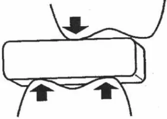
food particle is to apply a point force. This creates a large stress in the food particle
from a minimal force. The postcanine teeth are in fact shaped on this principle using
cusps to apply point forces. From this idea it may be thought that the sharper the cusps
are the better they will fracture the food particle. However the cusps on the post canine
teeth are not sharp but instead dull. In fact if the cusps are sharp they are more likely to
plastically deform the food particle rather than fracturing it (Lucas 2004c). The cusps
can therefore be thought of as being spherical in shape and when pressed onto the
food particle an indentation is made. The fracture force resulting from this indentation is proportional to the radius of the spherical cusp (Frank & Lawn 1967). This then would mean that dull cusps will fracture the food particles better than sharp ones. An example
of how the cusps of the postcanine teeth fracture food particles and how it can be
approximated to a three point bending can be seen in Figure 2-5.
[image:23.570.176.343.567.686.2]However not all foods fracture easily. Therefore the teeth require another method to
reduce the particle size of the food. A possible solution is that the post-canine teeth also
include a sharp blade like edge as used by the anterior teeth. This would give them the
ability to cut food particles by moving the blades over each other. The blades of the
upper teeth would then have to match the lower teeth. This is due to the fact that the
blades must make good contact when they pass over each other. The cusps on the
other hand do not need to be as precise as they are used to produce fractures ahead of
their path of travel. This explanation of the use of cusps and blades is the most likely
solution to apply to the design of the working surfaces of the post-canine teeth (Lucas
2004c). Because the teeth shape is important to the mechanism and effectiveness of
food mastication, the chewing device developed in this work must employ realistically
shaped teeth.
2.2.4 Forces on teeth
The forces applied on the teeth vary with the type of food that is being chewed. The
force applied to a single tooth is also different to that of total force between all the
contacting teeth during chewing. On foods such as biscuits, carrots and cooked meats
forces range between 70 and 150N on a single tooth (Anderson 1956), while forces on
all the contacting teeth range between 190 and 260N (Gibbs et al 1981 ). This is much
smaller than the maximum bite force that can be applied to the molars which measures
500 to 700N (Wood & Williams 1981 ). It is thought that these high forces must be
important in the process of thegosis or grinding teeth to sharpen the cusps (Every
1970). From the literature values an estimate of the maximum force that the chewing
device in this work is 150N.
2.2.5 Jaw trajectories during chewing
The first stage in the human chewing cycle involves the mandible opening thereby
creating a space between the teeth located on skull and the mandible. The tongue then
places food particles that need chewing on to the molars on one side of the mouth. The
mandible then closes and breaks up these food particles and then the particles fall off
the teeth back on to the tongue for positioning on the next cycle. If the food gets stuck
to the teeth most of the food would remain un-chewed. Therefore saliva is used to help
-Literature review
stop the food particles from sticking to the teeth and also helps to break down the food.
In extreme cases the tongue is used to pick food particles that get stuck off the teeth
(Lucas 2004b).
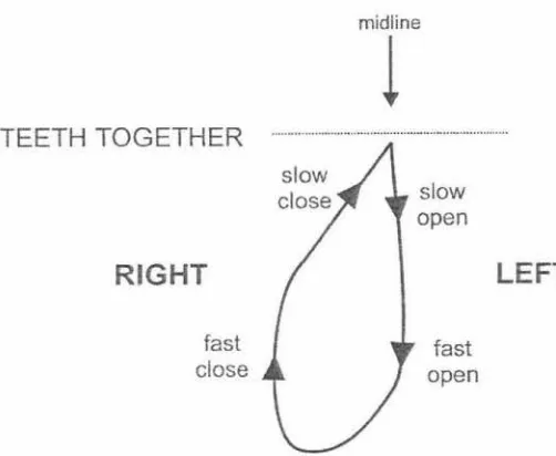
The opening of the mouth in the first stage of the chewing cycle is relatively vertical
(Mongini et al 1986). The speed of the mandible in the opening phase initially starts
slowly and increases as the mouth opens. But when the mouth starts to close, the
mandible moves laterally outward and initially closes quickly coming back towards the
teeth and then slows for occlusion. This can be seen in Figure 2-6.
The masticatory sequence
TEETH TOGETHER
R
I
GHT
fast
close
midline
!
slow
open
fast
[image:25.569.112.363.277.483.2]open
Figure 2-6 The masticatory sequence (taken from Lucas 2004b)
LEF
T
The trajectories of the teeth during chewing need to be characterised for different food
properties. This is required to determine how different foods affect the chewing
trajectories. The different chewing trajectories are represented in the frontal and sagittal planes which correspond to the planes looking at the front and side of the skull. Some
BENNETT MOVEMENT
A•flS• 138 .. TU
C)4l.l.H - IIIIGHT IIOC Cltt~,r -. . . TI$• "1•'\t1 t.H-:110( rn
Figure 2-7 Frontal and sagittal trajectories of a typical adult when chewing soft cheese on the right
side (taken from Gibbs & Lundeen 1982)
l
SCALEI
r-•
CM----1
Figure 2-8 Sagittal and frontal trajectories of a typical adult when chewing carrot (taken from Gibbs & Lundeen 1982)
-Literature review
I
Lateral range
]
I Ar ranj!e
I - - - - -- - -·
I
-I
I
I
I . I lI
'
I l
!
- - -- -~---·-I - - ----
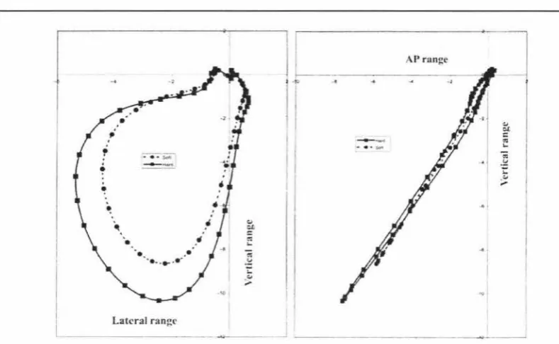
-Figure 2-9 Average frontal and sagittal trajectories for a typical adult when chewing hard and soft
gum (adapted from Anderson et al, 2002)
It can be seen from these figures that the chewing trajectories vary substantially. It can
be seen that the trajectories in the sagittal plane are very close to a straight line.
However from the literature reviewed it can vary from a vertical line where the teeth
come together at a zero degree angle and a line where the teeth come together at a 30
degree angle. The trajectories in the frontal plane can also be seen to change from
vertical profiles where the teeth occlude in a vertical fashion to lateral profiles where the
teeth slide across each other in a horizontal fashion. The presence of a straight line
trajectory in the sagittal plane presents the opportunity to reproduce the chewing motion
with a two-dimensional system. The orientation of this two-dimensional trajectory
however should be ideally adjustable from being directly in the sagittal plane (e.g.
Figure 2-7) to 30 degrees from this (see Figure 2-9 where there is some movement in
the sagittal plane).
The trajectories used to chew different food particles differ depending on both the
shape and the texture of the food particles. This is due to the fact that the teeth operate
differently depending on the chewing trajectory. If a vertical chewing motion is used, the
teeth use their cusps to fracture the food particles. Where as if a more lateral chewing
motion is used, the teeth use their sharp edges to function as blades and cut up the
food particles (Lucas 2004c). The chewing trajectory used is therefore adjusted to
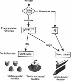
[image:27.568.45.440.70.313.2]of how to use the teeth, and therefore what chewing trajectory to use can be seen in
Figure 2-1 OError! Reference source not found .. It shows that in the first step of
deciding on how to use the teeth, the particle shape is detected and if the particles are
thin sheets or rods the teeth are used as blades to cut up the food. If however they are
thick blocks, then the texture is examined in the mouth. Lucas describes the texture as
being (R/E)°-5
, where R is the food toughness and E is Young's modulus of elasticity. If
(RIE)°-5 is low, the teeth use their cusps to fracture the food. If (R/E)0
·5 is high, then the
teeth once again use their sharp edges as blades to cut up the food. The application of
this model implies foods that require fracturing include peanuts and biscuits as they are
not tough and have a relatively high modulus of elasticity and therefore can be chewed
with a vertical chewing motion. While foods that require cutting include meats and
vegetables and therefore need to be chewed with a lateral chewing motion.
Fragmentation Criterion
Mastication
thid< blocks
low
+
Dental features
I
Blunt cusps••
••
'Multiple pestle' 'Pestle and mortar'
dentition dentition 'Double-bladed' dentition
Figure 2-10 The decision of what teeth function to use (adapted from Lucas 2004c)
Due to the fact that chewing is performed on the post canines, the chewing device must
follow the trajectories of the post canine teeth. However no data was found on the
trajectories of the post canine teeth during chewing. This is most likely due to the fact
-Literature review
that there has been limited research done on this as it is very difficult to accurately
measure the trajectories of the post canine teeth while chewing. A method to do this
would involve placing a sensor onto these teeth in order to measure the trajectories.
However it would not feel natural to the test subject to have such a sensor on the post
canine teeth while chewing. Therefore the chewing trajectories measured could in fact
be quite different due to the fact that test subject may alter there chewing to
compensate for the sensor in their mouth. There was however data available for incisor
trajectories. Therefore the relationship between incisor and molar trajectories was
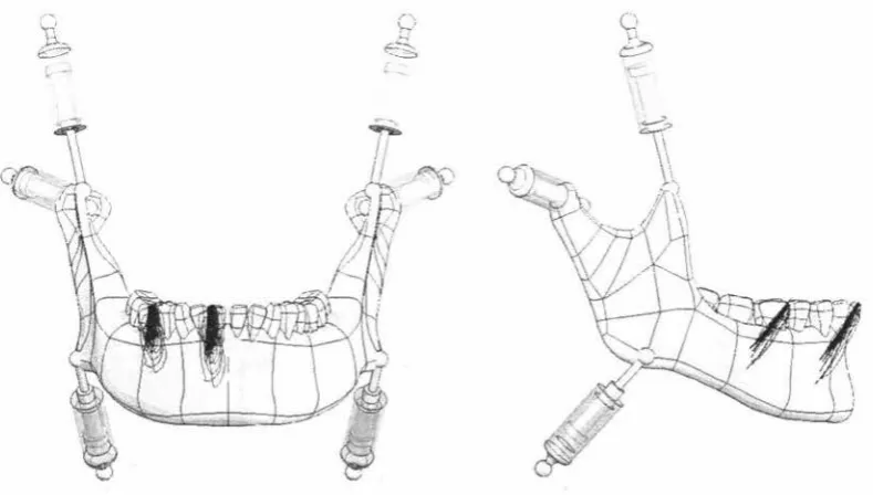
investigated. This was done by using a SolidWorks model (J.-S.Pap 2005) of the
human mandible and making it move by specifying a known incisor trajectory. This
model cen be seen in Figure 2-11. The trajectory of the first molar was then measured
and compared with the incisor trajectory. It was found that the trajectory of the first
molar where vertically compressed versions of the incisor trajectories. But the entry and
exit angle to and from occlusion were not greatly different. A comparison of a single
incisor and molar trajectory can be seen in Figure 2-12 Therefore data on the occlusal
[image:29.568.57.452.407.631.2]angles for incisors was used.
e
.§. C: " E " > 0 E ~ c " >• 5 .55 .45
1 st molar versus central incisor trajectories
.35 ·25 ·15 .5
·10
·20
·30 - lst molar trajectory
- Central incisor trajecto
Q
0
050.
Horizontal movement (mm)
Figure 2-12 Comparison between first molar and incisor chewing trajectories
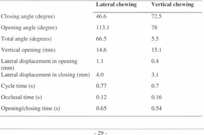
The angles that the teeth occlude at in the frontal plane can be seen in Table 1
(adapted from Ogawa et al. 2001 ). The data has divided the test subjects into vertical
and lateral chewing groups and also includes data on cycle time and velocities.
Table 1 Movement variables for vertical and horizontal chewing motions (adapted from Ogawa et al. 2001)
Lateral chewing Vertical chewing
Closin° an°1e (de0ree)
.:, .:, .:, 46.6 72.5
Opening angle (degree) 113.1 78
Total angle (degrees) 66.5 5.5
Vertical opening (mm) 14.6 15.1
Lateral displacement in opening I. I 0.4
(mm)
Lateral displacement in closing (mm) 4.0 3.1
Cycle time (s) 0.77 0.7
Occlusal time (s) 0.12 0.16
Opening/closing time (s) 0.65 0.54
[image:30.568.93.504.107.340.2] [image:30.568.95.499.486.754.2]-Literature review
Table 1 also shows some times for the opening, closing and occlusal phases of the chewing cycle. The time to complete a chewing cycle remains approximately the same for chewing foods with different properties (Anderson et al, 2002). This is due to the fact that the cycle time is controlled by the brain by neural circuitry called "central pattern generators" (Lund 1991 ). However everything else in the chewing cycle is very variable. Because the trajectory changes for different foods the chewing device being developed
in this work must be able to be adjusted to achieve both lateral (grinding) and vertical
(crunching) trajectories. The device should allow some flexibility in cycle time, the number of chewing cycles and occlusal time in order to be able to accurately reproduce
human chewing
2.3 Conclusion
From the research on the human chewing cycle it has been determined that the human
masticatory system is very complex. Therefore the parameters for the chewing device must closely match those of a human in order to reproduce food bolus preparation in the mouth. Therefore the chewing device is required to perform the following:
Trajectories
• The frontal trajectories for chewing different food types are to be approximated by the entry and exit angles at occlusion of lateral and vertical chewing motions
Table 2 Frontal trajectory properties (adapted from Ogawa et al 2001)
Lateral chewing Vertical chewing
Closing angle (degree) 46.6 72.5
Opening angle (degree) 113.1 78
Total angle (degrees) 66.5 5.5
Vertical opening (mm) 14.6 15.1
Lateral displacement in opening
I.
I 0.4(mm)
Lateral displacement in closing (mm) 4.0 3.1
• The trajectories in the sagittal plane can be approximated to a straight line. This line needs to be able to have a 30 degree adjustment from vertical to match the common sagittal trajectories found in humans.
• Perform the opening and closing phases of the chewing cycle in 0.65 of a second and perform the occlusal phase in 0.12 of a second.
Teeth
• Only the pre-molars and molars of one side of the jaw need to be included as mastication is only performed by these teeth and chewing only occurs on one side of the jaw at a time.
• Anatomically correct teeth must be used to chew the food. This is due to the fact that the teeth are complex in shape and it is unlikely that there function can be simulated without accurate representations of the occlusal surfaces.
• The location of the teeth in relation to other teeth must also be anatomically correct to ensure that they function correctly and that there is minimal wear on the teeth.
Other
• Be able to apply up to 150N of force during chewing.
• Reposition food between occlusal phases to ensure that the teeth are used in a fashion that is close to what a human does. This will help closely approximate the correct particle size distribution after mastication.
-Literature review
• Use a system to retain the food sample on the teeth and therefore simulate the retention function of the tongue and cheek.
3 Possible design approaches
3.1 Introduction
To achieve the specifications outlined in chapter two there are many possible robotic
systems that can provide a solution. Some of these systems are as follows:
• Four-bar linkage
• Cam system
• Two-axis system
• Platform robot
3.2 The four-bar linkage
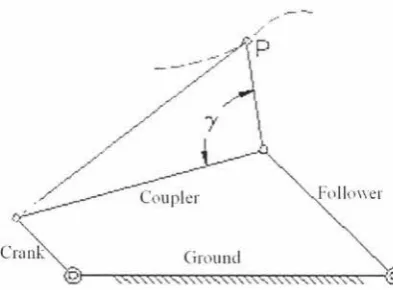
The four-bar linkage is a relatively simple mechanical mechanism and consists of four
links or 'bars' as the name suggests. The links are the crank, coupler, follower and
ground and they are connected as shown in Figure 3-1.
[image:34.566.192.389.418.563.2]Fl,llom:r
Figure 3-1 The four-bar linkage (adapted from Thompson 1999a)
The crank is the link that is driven and therefore produces the motion of the other links.
The crank has the ability to rotate a complete 360 degrees. The ground link is a link that
is fixed and does not move and has the task of locating the crank and follower a set
distance apart. The follower connects to the ground and coupler. This link has to be
large enough to stop itself from being able to make a complete turn when the crank is
driven. This is necessary as if the follower was able to turn 360 degrees the trajectories
of the coupler would be unpredictable and also could cause the mechanism to jam up
-Literature review
on itself. The coupler is connected to the crank and the follower and therefore has two
floating points. This means that the trajectory of the coupler is influenced by the crank
and follower. The point 'P' is used to achieve many different trajectories and is fixed in
relation to the coupler. The trajectory of this point depends on the lengths of all the links
as well as the position of the point 'P' in relation to the coupler. This system can provide
can provide consistently repeatable trajectories but can only approximate the
trajectories required. However this system is simple to control (Norton 2004).
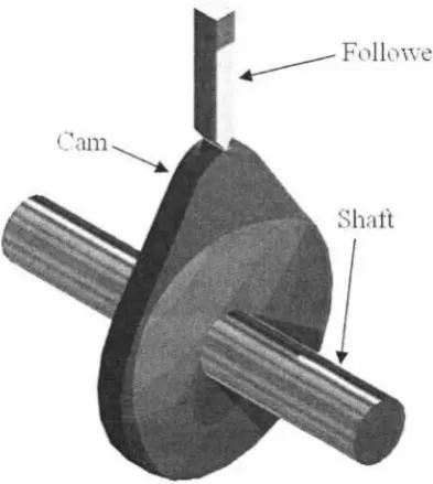
3.3 Cam trajectory system
Cams can be used to achieve different trajectories very easily. A cam system involves a
cam that is rotated on a shaft, and a cam follower that moves on the profile of the cam.
This can be seen in Figure 3-2.
Figure 3-2 The cam follower system (adapted from University of Limerick)
Systems like this are commonly found in combustion engines like your everyday car. In
this system the cam is used to open a valve to let a fuel/air mixture into the combustion
chamber or let exhaust gasses out. The valves move in a linear one-dimensional
motion where the motion is specified by the cam profile. However to achieve an
approximate chewing motion a trajectory is required in at least two-dimensions. This
then means that two cams would be required to actuate a follower making the system
[image:35.566.151.348.344.564.2]motion different cams would be required. This then means that the machine would either have to be disassembled to insert new cams or the cam system would have to
dynamically change cams. A system that dynamically changes cams can be found in Honda VTEC combustion engines in many Honda cars. This system has two different
cam profiles for each valve, one for low revs and one for high revs. The cam profile that
is used by the follower changes on command. This system has two cam followers that
follow the two different cams. One of these followers moves freely and does not effect
the movement of the valves. This can be seen in Figure 3-3.
Figure 3-3 VTEC system at low revs (taken from Honda marine)
To activate the other cam profile the cam followers are locked together by a pin and
then the valves are actuated by the larger cam. This can be seen in Figure 3-4.
Figure 3-4 VTEC system at high revs (taken from Honda marine)
-Literature review
However a system such as this gets complicated very quickly if adapted for a two-dimensional trajectory system. It also only allows a few set trajectories and can not produce intermediate trajectories.
3.4 Two-axis trajectory system
Two-axis trajectory systems are widely used in systems such as scanners, printers and microscope tables. This system involves using two actuators positioned perpendicular to each other to move an actuating point. A system like this is mechanically simple and is also simple from a manufacturing point of view. This is due to the fact that the actuators can be purchased leaving only the mounting systems that need to be constructed. However the two actuators need to move at the same time. This then means that the control system to control the actuators is relatively complex. But due to the fact that this system uses a controller to make the actuators perform the desired trajectory means that the chewing trajectory can be changed by reprogramming the controller rather than making a new mechanism. It also means that the chewing trajectory can be dynamically changed from chewing cycle to chewing cycle. This however would require complex trajectory planning.
3.5 Platform robot
Figure 3-5 A hexapod platform robot (taken from Physic Instrumente 1996-2005)
This system would ideally suit a robot that simulates the human chewing behaviour.
This is due to the fact that the human jaw can be thought of a two parallel plates where
the mandible corresponds to the actuated plate and the skull corresponds to the fixed
plate. A hexapod system such as this is also simple from a manufacturing stand point
as only the two plates need to be constructed if the actuators are purchased. Although
this would be an ideal solution the control of the system is very complex. This is due to
the fact that there are six actuators that are required to move at the same time.
Therefore trajectory planning becomes very difficult.
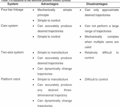
3.6 Robotic system evaluation
The robotic systems mentioned all have the ability to produce trajectories for chewing. Each of the
systems has advantages and disadvantages and can be seen in
Table 3.
-Possible design approaches
Table 3 Evaluation of the different possible robotic systems
System Advantages
Four-bar linkage
Cam system
Two-axis system
Platform robot
• Mechanically
principle
• Simple to control
simple
• Can accurately produce
desired trajectories
• Simple to control
• Simple to manufacture
• Can accurately produce
desired trajectories
• Can dynamically change
trajectories
• Simple to manufacture
• Can accurately produce
any desired
three-dimensional trajectory
• Can dynamically change
trajectories
Disadvantages
• Can only approximate
desired trajectories
• Can not perform a large
range of trajectories
• Mechanically complex
when multiple cams are
used
• Relatively difficult to
control
• Difficult to control
As a prototype device is required in a relatively short time frame, a simple robotic
system must be used. Therefore the four-bar linkage system was chosen. This will
closely approximate the chewing trajectories and can be made robust due to its simple
4 Four-bar linkage mechanism design
4.1 Introduction
The design of the four-bar linkage must facilitate the chewing of a variety of different foods. Due to the fact that humans chew foods with different properties differently, the four-bar linkage must be able to be adjusted to achieve the required motions for these food types.
4
.
2 Specifications
For the device to achieve an appropriate chewing motion of the human masticatory cycle, it must achieve the following parameters:
• It must apply up to a maximum force of 150 Newtons to the food sample.
• It must achieve a range of set trajectories in the frontal plane with the occlusion entry and exit angles being very close to the desired angles. These angles can
be seen in section 2.3.
• The time taken for the opening, closing and occlusion phases must be very close to that of the human chewing cycle. These times can be seen in Table 2.
4.3 Linkage design
4.3.1 Constraints
The four-bar linkage is limited by the fact that it is difficult to design it to perform a desired trajectory. It will however constantly perform a set trajectory making it highly
repeatable. As the four-bar linkage can only perform one set trajectory in its standard
form means that it is limited in its adaptability. Some adaptability can be added by
designing links that adjustable length. This is difficult to implement on all links except the ground link. The reason for this is that all the links move apart from the ground link.
Therefore in this case where some adaptability is required to reproduce a range of
trajectories, the ground link must incorporate some adjustability to approximate different
chewing trajectories for different food types.
-Four-bar linkage mechanism design
4.3.2 Design approaches
There are two common design approaches to ensure that the trajectory that the mechanism achieves is close to that desired. They are:
• The four-bar atlas approach, and
• The genetic algorithm approach
The four-bar atlas approach involves selecting a trajectory that is close to the desired trajectory from an atlas that has many different trajectories plotted in it. The link lengths and the position of the trajectory generating point in relation to the coupler are the determined by the use of a look-up table that specifies the parameters to the desired trajectory.
The genetic algorithm approach involves writing a genetic algorithm that takes the desired trajectory and makes a trajectory that closely matches it by changing the parameters of the linkage. This is a numeric solution that evaluates the trajectory produced by a set of linkage parameters. It then changes the linkage parameters and evaluates the new trajectory. This is done for many iterations and returns the parameters of the linkage that produces the trajectory with the least amount of error (Charbonneau et al, 2004).
Due to the fact that the genetic algorithm method requires a genetic algorithm program to be developed, it is rather time consuming and is not ideally suited for this application where only one set of link parameters is required to be found. It would however be very useful if different four-bar linkage parameters needed to be found on a number of different occasions. Therefore the four-bar atlas was chosen to be used, as it can provide the specifications for the four-bar linkage from a look-up table where the trajectories can be firstly visually evaluated to get a set of preliminary link specifications. From here further trajectory analysis can be used to determine the most suitable trajectory and therefore the most suitable link specifications.
Limit and dead positions of a four-bar linkage occur when the crank and coupler form a
straight line. This is due to the fact that the coupler transfers the force applied from
either the crank or the follower in the direction of the coupler. As the crank and coupler
form a straight line twice per cycle there are either two limit or two dead positions per
cycle. These can be seen in Figure 4-1. A dead position is when the follower can not
make the crank rotate when a torque is applied to it; therefore it has no mechanical
advantage. A limit position on the other hand is where the crank can be used to apply
an infinite mechanical advantage to the follower. Dead positions also occur if the
follower and coupler form a straight line when driven by the crank. This means that the
sum of the lengths of the coupler and the follower must be larger than the sum of the
ground and crank lengths.
·'
I '
\ '\ \ \
\ \ I \
I \
1 \
I \ I I I l I \ I \ I I
I I
J I I J ' I \
\
\ \
'
Figure 4-1 Limit and dead configurations of a four-bar linkage (taken from Stanisic)
The transmission angle is the angle between the follower and coupler. This angle varies
as the mechanism is driven and serves as an indicator of how well the linkage can
transmit torque from the crank to the follower. The maximum transmission angle µmax and the minimum transmission angle µmin can be seen in Figure 4-2. The general rule
for the transmission angle is to never allow it to be less than 30 degrees or greater than
150 degrees (Erdman et al, 2001 ). If the minimum transmission angle was zero degrees
or the maximum transmission angle was 180 degrees the mechanism would then have
the coupler and the crank forming a straight line and would therefore be in a dead
position. In practice this could cause the mechanism to fold over on itself as the coupler
has two possible directions in which to travel. This means that the coupler could change
its operating side resulting in irregular operation.
-Four-bar linkage mechanism design
input
fil_
--
--
---
-
---
~
,l'/f?/ Z"/,(''
Figure 4-2 The maximum and minimum transmission angles (taken from Stanisic)
4.3.3 The four-bar design
The four-bar linkage was designed using the traditional four-bar atlas approach rather than genetic algorithms which had been used during a preliminary stage of this research [Charbonneau et al, 2004]. This was due to the fact that the results from this genetic algorithm were not as good as expected and it was more time efficient to use a four-bar atlas to look up a desired trajectory and link specifications rather than redesigning the genetic algorithm program.
The Cedarville engineering four-bar web atlas (Thompson 1999b) was used to find a number of suitable trajectories that had entry and exit angles that closely matched a lateral chewing cycle described in section 2.3. Trajectories where searched for by adjusting the parameters of a four-bar linkage shown in Figure 4-3 where link 'a' is the crank, link 'b' is the coupler, link 'c' is the follower and link 'd' is the ground. The point 'P'
is the trajectory generating point that is located at and angle of 'y' from the coupler length 'b' and a distance 'BP' from point 'B'.
A
When a trajectory was found that looked close to matching the desired occlusal angles
of a lateral chewing motion it was marked down as a possible solution. However vertical
chewing motions are also required when the ground link length is changed. Therefore
the derivatives of these possible solutions where examined by changing the ground link
length and observing how the trajectory responded. The link parameters that made trajectories that seemed close to both vertical and lateral chewing trajectories were
noted. Some sample trajectories can be seen in Figure 4-4 and Figure 4-5. Figure 4-4 shows the final choice of the lateral chewing trajectory. The link parameters are shown at the top and the figure while the 'BP' length is read off the graph from the zero point to
the point that falls on the desired trajectory (3 in this case). Figure 4-5 shows a
derivative of the chosen lateral trajectory. It can be seen that the ground link length 'd'
has been reduced from 5 to 4 to achieve a vertical chewing trajectory.
5 4 3 2 1 C
E
"iii 0 0 0... >--1 -2 -3 -4 -5-5
. ._ --...__ , I I I ' I I J I I I I ,..
Four-bar Coupler Curves and Centrodes
a=1 b=3 501 c=3 002 d=5.0025 ·.,=60°
\
\ \
\
I., ...
,
,
' ...__
~
' /V
,,
~
-
\ ,; , ,I '
-s__ . ~ ,
.
\,
,.
,.
-
, ,.
"1
x
/ .
I I \ ' ' ' ' t I I ' I
' , ' I ,'"i.,
'-A
I / I '
' I I \ , I '
I
I I
\ I
I
' I ," \ ,' r\
' I \ I I ' / ' 1
1, \ I I I , I I (
.·
"
V
~
' ' ,\
, J / ' .. -· ......
} I
I
I,' I
/
tl I t.." ,
"
,,
' \
"~-'V
~'
·
I. I
I ' , I
\
/
"'---·
-
.
\
\
-= I I r-...\
-4 -3 -2 -1 0 1 2 3 4
X Position
[image:44.565.123.459.347.714.2]5
Figure 4-4 Candidate trajectories of the four-bar linkage (adapted from Thompson 1999b)
-Four-bar linkage mechanism design
5
4
'-3 2 1 C
.
_g
(/) 0 0 Q.r
I
-
Jf
Four-bar Coupler Curves and Centrodes
a=1 b=3.501 c=3.002 d=4.0025 ·.·=60°
·,,
'
' '• ' ' ' ~ I ·, ,. \:'~
•,. ''
....
J-;, '' f \
I I I I J I
r,,,
=
-~ I-.:....r.
V:I
' ...._
--.;
,-
\
-
,
~
\ I:
I
.' I I
--
V\ \ ,1 \ I ' .
,
J:
i-/
' '
.
t - - - '-1
I\
,\ ' IV]
•._--.
-2
-3
-4
J f
' I ' r \
i\:
' I , IG·'
I f I
u
'. Ir I I ,
I
.
I I f ,
_
/
·v ,JI I \. , ' : v" ,,
I '. : ' .. _,,// ' ' ' \ ' \ ·'
.
.
/ ' v 'I
I
\
--5 I
-5 -4 -3 -2 -1 0 2 3 4 5
X Position
Figure 4-5 Candidate trajectories when the ground length is reduced (adapted from Thom1>son
1999b)
These trajectories were then examined further to determine the exact occlusal angle. It
was determined that the trajectories shown in Figure 4-4 and Figure 4-5 were in fact the
best solution that were found. The final values can be seen below. However these
values are only ratios and the links can be any length as long as the ratios are obeyed.
The final ratios of the four-bar linkage are:
Crank (link 'a') = 1
Follower (link 'c') = 3
Ground (link 'd') = 3.8 - 5 to achieve horizontal and vertical chewing motions
Coupler (link 'b') = 3.5
[image:45.564.78.421.105.481.2]Coupler (angle 'y') =60 degrees
A simple model was constructed in SolidWorks to evaluate different link lengths as seen
in Figure 4-6. The factor that limits how small the linkage can be made is the crank as it has the smallest dimensions and has to be able to incorporate shafts strong enough to
securely connect the individual links of the linkage. For this reason it was decided to
make the crank length 10mm. This also allows the linkage to be as compact as
possible. The entire mechanism also had to be rotated 65 degrees to orientate the trajectory produced by the four bar linkage. This was required so that the teeth could be
[image:46.564.191.376.281.456.2]mounted vertically.
Figure 4-6 Simple model to evaluate different link lengths
The final four-bar linkage parameters were:
Crank (link 'a') = 10mm
Follower (link 'c') = 30mm
Ground (link 'd') = 38mm - 50mm
Coupler (link 'b') = 35mm
Coupler (distance 'BP')= 30mm
Coupler (angle 'y') =60 degrees
65 degrees
These sets of results were then evaluated by comparing the entry and exit angles at
occlusion with the data obtained in chapter two that shows lateral and vertical chewing motion. It can be seen from the data in Table 4 that using the four-bar linkage
mechanism proposed, the vertical opening distances as well as the lateral
-Four-bar linkage mechanism design
displacements are larger than those observed in the experimental data reported by
Ogawa et al (2004). This is acceptable as these aspects of the chewing trajectory do
not impact on the food breakdown process as long as they are sufficient to clear the
food between chewing cycles. The motor can be speed up during this part of the cycle
to ensure representative masticatory behaviour can be simulated. The chosen design is
optimised to achieve a close match with the lateral chewing trajectory while still
achieving reasonable trajectories for the vertical chewing process.
Table 4 Comparison between the designed four-bar linkage and the experimental data (adapted from Ogawa et al, 2004)
Closing angle (degree)
Opening angle (degree)
Total angle (degrees)
Vertical opening (mm)
Lateral displacement in opening (mm)
Lateral displacement in
closing (mm)
\"erllcal
.. 1penmg
Lateral chewing From data Four-bar
46.6 45
113.1 112
66.5 67
14.6 23
I. I .., .)
4.0
9
\
Opemng nn!tle\ [image:47.564.35.452.267.494.2]\
·
.
.
.
...
.
.
·
·
...
I.,
Vertical chewing
From data Four-bar
72.5
99
78 105
5.5 6
15.1 34
0.4 3
3.1 0
Closu1?: ..u11-de
L11ternl ope11U1p; chsplacement Lnteral closinµ. dL,plncement
Some sample trajectories that the four-bar linkage can perform can be seen in Figure
4-8. It shows different trajectories when adjusting the ground-link. It also shows that
other parameters change when the ground link dimension is adjusted. It can be seen
that the occlusal position moves as well as the vertical opening distance increasing as
the ground link dimension decreases. This is due to the nature of the four-bar linkage
and can not be helped. This however means that the chewing device needs some way
of adjusting the occlusal position of the teeth.
Chewing trajectories achieved when adjusting the groln1d link
30
20
15
1(1
5
-100 .cl,)
\f
-70 -60 . 0-5
• 10
[image:48.564.79.505.259.484.2]Distance (mm)
Figure 4-8 Sample trajectories that the four-bar linkage can achieve
-40
-+-5umm ground
44mm ground
... Jemm ground
The vertical and horizontal trajectories can be viewed as a function of the crank angle
as shown in Figure 4-9 and Figure 4-10. Figure 4-9 shows that the actuating point on
the coupler reaches maximum displacement at approximately 150 degrees when the
ground link is 50mm. While Figure 4-10 shows that there is a maximum horizontal
movement of approximately 11 mm when the ground link is 50mm. This gives a good
indication of how the mechanism responds in both the vertical and horizontal directions
when the crank is driven.