THE BUCKLING OF STRUCTURES
WITH PARTICULAR REFERENCE TO
STRUCTURES CONTAINING BOLTED ANGLE-SECTION MEMBERS AND
LIGHTWEIGHT STRUCTURES
By M. Gregory
A Thesis submitted for the degree of Doctor of Philosophy in the
Faculty of Engineering of the
University of Tasmania.
Civil Engineering Department, The University of Tasmania.
-PREFACE-
Ths work described in this thesis has been carried out in the Civil Engineering Department of the University of Tasmania during the period July, 1956 to
February, 1960. The research has been directed at obtaining some fundamental understanding of problems of instability of structures rather than the production of empirical information necessary for design purposes, though it is believed that the groundwork has been laid for the determination of valuable empirical data on certain types of problems. The treatment is restricted in the main to elastic buckling of non-redundant frames, •though the problems met with in inelastic behaviour or with redundant frames are mentioned, and have been kept in mind throughout.
Chapter One begins with a detailed analysis of an unstable mechanism. This study forms an interesting
introduction to problems of instability of structures without introducing the complication of the elastic beam equation.
Various methods of analysis of structures have their counterpart, by analogy, in the treatment of the behaviour of this mechanism, and the treatment is rather detailed. The remainder of the chapter is devoted to standard methods of calculation of elastic critical loads. Because of the apparent confusion
in some recent papers as to the meaning of various critical
loads as determined by the moment distribution convergence criterion and other methods, the treatment is again rather full, and contains some very simple examples. More difficult problems are worked as illustrations and also because their results are used later.
Chapter Two is concerned with pin-ended struts and gives an introduction to the use of the Southwell Plot and the information that can be obtained from it. The Southwell Plot on deflections is first discussed. Particular emphasis is then laid on the power of the Southwell Plot on strain measurements. It is believed that the strain plot may have been used to ensure centrality of loading of a column for testing, but otherwise the treatment is new. It is intended that the discussion of single columns should furnish a basis for the arguments developed in Chapter Three,
In Chapter Three the Southwell Plot on strains is applied to a number of simple model frames and model or full-size structures. A design
method for certain types of
structures liable
to instability is advanced, based on the
equation of the Southwell Plot on measured strains.
This
work is new. The Southwell Plot on deflections has been used previously to confirm calculated values of critical loads of structures, but the equation of any Southwell Plot, and in particular the plot on strains, can be used to take account of imperfections and to relate the performance of
the
actual structure to the critical load of the perfect structure.
The investigation has followed the method
of first establishing criteria analytically in the case of anumber of simple frames, followed by experimental verification.
More
complicated frames were then treated.
been previously noticed. The behaviour is reported here, as there is probably a considerable effect on the torsion buckling of angle-section and similar members. (The general analysis of the bending and shortening effect of pure torque has since been carried out, but is not included in this thesis. See Aust. J. Appl. Science, Vol. 11, No.
3
(1960.) The remainder of the chapter contains the results of studies on model structures containing bolted angle members. A method of attack on the problem of obtaining design data is suggested.It is thought that complementary energy methods will furnish the main means of tackling the problems of
redundant frames. In view of the importance of energy
methods in structural analysis, Chapter Five contains a brief outline of their application. The treatment is
rather short and may be considered as a simple introduction to the problems of redundant frames. A pin-jointed redundant frame is solved by complementary energy, the crookedness of members being taken into account. However, any analysis of the behaviour of even the simplest rigid-jointed redundant frames is a problem of considerable complexity, and the
determination of its strength is still more difficult.
Nevertheless, it is the author's opinion that energy methods of analysis backed by the empirical information obtainable from Southwell Plots on strains will ultimately give a solution.
Experimental work connected with this investigation has involved the testing of over twenty full-size girders and
trusses, a model lattice girder, model Warren trusses,
eleven
triangulated model frames containing
bolted angle members ) and
numerous triangular frames and single members.
Since considerable
information could often be obtained without causing permanent deformation, many of the frames or members tested wereused
over and over again.
The method followed in this research has been firstly to study simple problems such as single members or triangular frames, techniques and ideas being worked out
analytically and experimentally on
theseproblems as far as
possible. Information gained in this way was then extended,often by analogy, to more difficult problems, then
supported
by experimental means and, where possible, analytically.
The
advantage of the prior study of simple problems for theclarification of ideas, the evaluation of the accuracy of any method, and for perfection of technique, is not always realised.
It is the intention of this thesis to propose the use of the Southwell Plot on strains or related plots as a basis for the determination of design formulae in problems of instability. It is considered that sufficient indication of the value of the method is given here to warrant the undertaking of research and testing on a large scale in order to determine the necessary empirical data for all types of structures.
r-k
Acknowledgements :
The author has published a number of papers and communications dealing with this research, and a considerable quantity of this material is embodied in this thesis. A list is appended after Chapter Five, where acknowledgement is given to the periodicals and journals concerned. Where relevant, the author wishes to thank the editors for their permission to use
material they have published.
Some of the argument and discussion in this thesis is drawn from various books and papers. References are given in the text, and an additional bibliograpuy, with accompanying notes is given after each chapter. The author apologizes for any omissions. Where
acknowledgement is not given in this way, the work is that of the author.
In conclusion the author wishes to thank the following persons:
Professor A. R. Oliver, the Professor of Civil Engineering in the University of Tasmania and supervisor of research;
Sir Richard Southwell, Trumpington, Cambridge, for his
continued patience and kindness in giving helpful advice and encouragement by correspondence;
Professor dr. ir . C. B. Biezeno, Technische Hogeschool, Delft, Holland; Professor J. A. L. Matheson, formerly of the University of Manchester, now of Monash University, Melbourne, Victoria; and T. M. Charlton, University of Cambridge, for their comments and replies to questions on various aspects of the work.
THE BUCKLING OF STRUCTURES
CONTENTS
CHAPTER ONE:
THEORY OF BUCKLING: The Buckling of a Simple Mechanism, Elements of Structures, and Plane Triangulated
Frames .. Page 1.
CHAPTER TWO:
THE LOAD CARRYING CAPACITY OF PIN-
ENDED STRUTS .. Page 39.
CHAPTER THREE:
THE USE OF THE SOUTHWELL PLOT ON STRAINS TO ESTIMATE THE LOAD
CARRYING CAPACITY OF STRUCTURES
LIABLE TO INSTABILITY .. Page 54.
CHAPTER FOUR:
BOLTED ANGLE STRUTS (With particular reference to the design of transmission
towers . ) .. Page 91.
CHAPTER FIVE:
_REDUNDANT STRUCTURES 0. Page 114.
'71e
CHAPTER 1.
THEORY OF BUCKLES G.
THE BUCKLING OF A SIMPLE MECHANISM, ELEMENTS OF STRUCTURES, AND PLANE TRIANGULATED FRAMES.
1. Introduction
In this chapter, the notion of unstable equilibrium of a structure'is introduced by an analysis of the behaviour of a simple rod and spring mechanism. In this simple way, without the necessity of handling the equations of bending of a beam, the idea of a critical load at which the structure is in neutral equilibrium against static digturbancesis presented. By this means it is possible to examine buckling divorced from the complication of the beam equation. The various energy and zero stiffness .principles are worked out on this model, and also the related behaviour of the slightly imperfect structure.
• 'The classical methods of calculation of buckling loads of single members and structures are then given, energy pri,hciplee being very briefly reviewed. Various recent methods of handling the relevant equations for framed structures are illustrated with worked examples, the common
mathematical foundation for all the methods being kept in mind
throughout.
The way in which the behaviour of the practical structure under load may depart from the simple neutral equilibrium theory is briefly
outlined. 2. Notation . ,
The general notation used is as follows: Compressive force.
T. . Tensile force. Bending moment. of
e.
Rotation of. end L o t Length of a member. U • Energy.'F, W
FordeS, loads.
Displacement, deflection.
Young*modulus..
El
FleXural rigidity.
Other.symbols are•explained_in . the.teprt.
nifulguitlarigiulLAsagapuitimuLtaiLkati_
elastically restrained
at
one end.
•
,The.simple mechanism treated here is taken from an
article. by.N..J..
Hoff,"Dynamic Criteria of Buckling". - Research,
Engineering Structures.$upplement,
.(1949)
p. 121 (ButterwOrth) in which the, dynamic bucklingis analysed,..Various.types of damping being' discussed.
In this thesisp -however, the meChanism is used to
illustrate the principle of Unstable.equilibrium and
'methods of calculation of
:critical
loads whichare. later used in relation tO.the buckling
of structures. The analysis of
the undampened vibration ii:_taken fibm Hoff's paper, but the remainder is
the work of the author. • •
Fig. 1 Fi
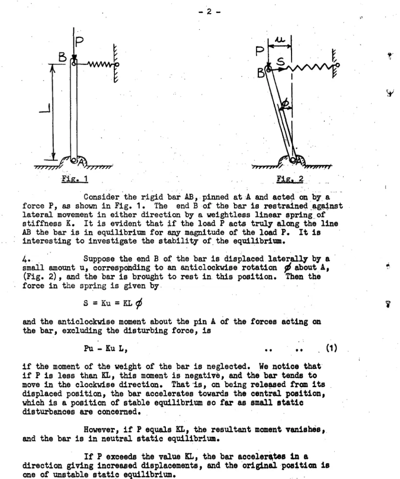
Consider the rigid bar AB, pinned at A and acted on by a force PI as shown in Fig. 1. The end B of the bar is restrained against lateral movement in either direction by a weightless linear spring of stiffness K. It is evident that if the load P acts truly along the line AB the bar is in equilibrium for any magnitude of the load P. It is interesting to investigate the stability of the equilibrium.
4.• Suppose the end B of the bar is displaced laterally by a
small amount u, corresponding to an anticlockwise rotation Ofabout A, (Fig. 2), and the bar is brought to rest in. this position. Then the force in the spring is given by
S = Ku = XL
and the anticlockwise moment about the pin A of the forces acting on the bar, excluding the disturbing force, is
Pu - Ku L, (1)
if the moment of the weight of the bar is neglected. He notice that' if P is less than KL, this moment is negative, and the bar tends to move in the clockwise direction. That .is, on being released from its . displaced position, the bar accelerates towards the central position, which is a position of stable equilibrium so far as small static disturbances are concerned.
However, if P equals XL, the resultant moment vanishes,. and the bar is in neutral static equilibrium.
If P exceeds the value KL, the
bar accelerates in a
direction giving increased displacements, and the 'original position is
one of unstable static equilibrium.
5. It can be seen that the stability of the. 'equilibrium
position depends on the relation between the magnitude of the acting
force P and the stiffness: of the restraining spring. If-we consider
the behaviour of the system as P is increased from zero, small static
disturbances of the type described being given from time to time, then
for values of P less than 4L the effect of a disturbance is.-to set tip
a small oscillation about the equilibrium position. If P equals
XL,when'the
baris displaced it does not return. A very slight increase
In load is then sufficient to
cause large deflections. after a slight disturbance.' It is interesting to note that the argument, and in particular the value of the critical load at which instability occurs, is independent of the magnitude of the displacement provided the displacement is small, since the condition for instability is-I
Pu - KuL > 0 •• • • (2) which yieldsP > KL, whatever the magnitude of u.
6. The effect of a dynamic disturbance can also be investigated. If the mass moment of inertia of the bar about the hinge A is I, and at some instant the bar is in the position shown in Fig. 2, then the
equation of motion is
I d2 y6/dt2 + KL2 56 - PL
=
This givesd20. /dt,2 + L (KL = 0 0 0 (3) Putting
1
(KL - P)L/I( = k 2 , the solution of this equation is = •A sin (kt + B) provided KL;PP, Case 1. )or d 0/dt = constant if KL =P 1 Case 2. ) (4) or 0 = A sinh (kt + B) if KL<P, Case 3. )
A and B being arbitrary constants.
As a boundary condition, put
d0/dt = v/i, when t = o and ci3 =
That is, consider the motion when the end B of the bar is given an initial, velocity v at the equilibrium position. Equations (4) then reduce to
. 5=.. (vAL) sin kt if P < KL, Case 1. ) )
or = vt/L . if P = KL, Case 2. ) .. (5) )
Or 0 = v/kL sinh kt if P>. KL, Case 3• )
If P is less than KL, Case 1 gives the equation of a vibration about. the equilibrium position of amplitude 0 = v/kL and frequency k/211 . If P equals KL,
0
assumes values Which increase steadily with time. If P is greater than KL, the acceleration away from the position of equilibrium is very rapid. The study of a dynamic disturbance leads to results which agree physically with the conclusions drawn from the analysis of a static disturbance. It should be remembered that the argument is restricted to small displacements._
8. Consider the energy changes involved in a small dynamic displacement of the bar from its equilibrium position, as shown in Fig. 2. At any instant, they may be listed as follows the equilibrium position being considered as a datum.
U1 '= the work done by the load P
= PL ( 1 - cos
0)
= 2PL sin 2 ( 0/2) = PI; 4t2/2 for small , = the energy stored in the spring= KL2 2 r 62
-
u3 the energy introduced into the system from outside, in
order to cause the disturbance, called the perturbation energy.
U4 = the kinetic energy of the rod = I(dy6/dt) 2
The spring is considered weightless. Then, we have U
1 + U3 -= U2 +J4
assuming conservation of energy. It can be seen that when P = KL, U1 = U. The effect of a perturbation, of energy U3, may now be summarised.
(1) When P<KL, U 1 <U21 and hence U l > 17,. Part of the perturbation energy is required to deform tge
saing,
and the remainder is converted into kinetic energy.(2) When P = KL, U 1 = U 2 , and hence U3 = U4. The perturbation energy is converted into kinetic energy.
(3) When P > KL, U1 > U2, and hence U3 <U,. More kinetic energy is available than provided by the disturbance, as the work available from the load P exceeds the work required to deform the spring. Hence a vanishingly small perturbation energy is sufficient to upset the equilibrium. The system is dynamically unstable.
•
The argument is simplified by putting U3 = 0, when the
criterion for neutral or unstable equilibrium under. static displacements . becomes
U1
7
u2
• •_ (6)
_ . This principle is very powerful in the determination of the critical loads of structures.
9.
It has been shown (Equations (5), Case 1) that, on displacement and release, the rod executes harmonic vibrations about its equilibrium position if P is less than KL. We have=
(v/kL) sin kt.Assume for the moment that the frequency of vibration (and hence k) is unknown, though the motion is known to be harmonic. Put
The kinetic energy at 0 = o is I(d0/dt) 2/2 = IA 2 44)2/2.
When 0 reaches its maximum value, #= A, the kinetic energy, is zero. Conservation of energy then gives that the kinetic energy at 0= 0 . plus the energy given up by the load in the motion out to 0= A equals
the energy stored in the spring at 0= A. Hence c-f
IA 2 64)/2
cos.Atax)
.- 2Therefore IL202
PLA =
2 A2 and 44) 2 = (XL - P) LAIKL2 2niax 2 .
and the result is independent of the amplitude A of the vibration, provided
A
is small. The value of 4A) is in agreement with the value of k obtained from equation (3). Use of the energy principle furnishes an easy. means of obtaining the frequency of harmonic vibrations of - astable system about its equilibrium position. It should be noticed that as P approaches the value KI4 m) tends to
zero, and the frequency of 'the
vibration tends to zero.10. Consider the stiffness of the rod and spring system against
a
disturbing force F applied at B in the direction normal to P. (Fig. 3).
J3on
Then for ,equilibrium, we have
Pu - KuL + FL =0.
The stiffness of the system against the force F is F/U and equals
(KL - P)/L. It is' positive for P<KL and becomes zero for P = KL
and negative for P>KL: If P is considered as increasing from zero,
small disturbing forces being applied from time to time, then as P
approaches the value XL, F/U tends to zero, and a vanishingly small
disturbing force causes large displacements. This principle is of
use in determining the loads at which instability occurs in structures.
. It should also be noted that for a given value of P, F/U is
constant,,and the work done by the disturbing force is Fu/2 and equals
(KL - P)e/2L, which is positive so long at KO. P.
It can also be seen that as P approaches the value KL large
'forceisrS =-Ku are calledinto play in the spring to resist the' action
— 6 —
11. The practical implications of the liability of certain
structures to instability are very wide. The rod and spring mechanism
has served to illustrate certain concepts, but, in practice, many more complications are introduced. Problems which are relevant to the study of the rod and spring system, each of which has its counterpart in the study of the instability of structures, are the effect of a non-linear spring, the effect of damping or friction, the effect of large displacements,' or the effect of a change in the load P as the system displaces'. 'It may occur that P is not constant, but a function
of the distance through which it acts, or a function of the rate Of displacement. The relation between P and'u may be affected by-the. inertia of the bar and Of the loading apparatus, as this' will affect the speed with which the load can "follow" the movement of the bar. The qualitative effects of such variations from the simple problem discussed may sometimes be evident, but
the quantitive effects are
also important in practice:
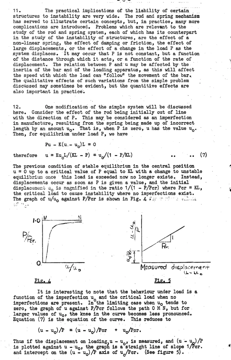
12. One modification of the simple system will be discussed here. Consider the effect of
the rod
being initially out of line with the direction of P. This may be considered as an imperfection in manufacture, resulting from the spring being made up of incorrect length by an amount to. That is, when P is zero, u had the value to. Then, for equilibrium under loadP,
we haveFu - K(u_- uo)L =0
therefore u = KuoL/(KL - P) = u0/(1 - PAL) (7) The previous condition of stable equilibrium in the
central position
u =
0 up to a critical value of P equal to KLwith a change to unstable
equilibrium once this load is exceeded now no longer exists.
Instead,
displacements occur as soon as P is given a value, and the initial
displacement ao is magnified in the ratio 1A1 - P/Pcr) where Per = KL, the critical load to cause instability where no imperfections exist. The graph of u/to against P/Pcr is shown in Fig.
4
er
Mcosureci ol.sp!acerf
■e
nr,
Fig.
4
Fig. 5It is interesting to note that the behaviour under load is a
function of the imperfection 12
0
and the critical load when no
imperfections are present. In the limiting case when ti
c
, tends to
zero, the graph of u against P/Por follows the path
0 MN, but for,
, larger values of u
s:)
, the knee in the curve becomes less pronounced.
Equation (7) is the equation of the' curve This reduces to
(u - u
o
=
Oa —u
o
Oor + u
0
/cr.
Thus if thedisplacement on loading ,u - 12
0
-is measured, and (u - u
n
)/P
Is plotted 'against u
.1.10 ,the graph
isa straight line of
slope 1/Per.and intercept on the (u - u
0
)/ axis of u
0
/Por. (See' figure5).
This plot forms a convenient means of relating the measured behaviour of an imperfect system to the magnitude of its imperfections and the critical load of the perfect system.
13. Under load, the behaviour of structures liable to instability is usually similar to that of the rod and spring model possessing
imperfections, (Fig. 4), rather than the case where no imperfections are present. The latter behaviour is a limiting case of the former, and difficult to obtain in practice. Both types of behaviour are often referred to as buckling. There is a close relation between the two. In practice, buckling usually means the occurrence of large deformations with a smAll change in load (and there is often no true instability.) This occurs on the upper parts of the curves in Fig.
4.
We are often interested in the load carrying capacity of structures, and wherebuckling occurs such problems can be tackled by a study of the behaviour of idealized structures, followed by analysis and empirical correlation of the effects of imperfections.
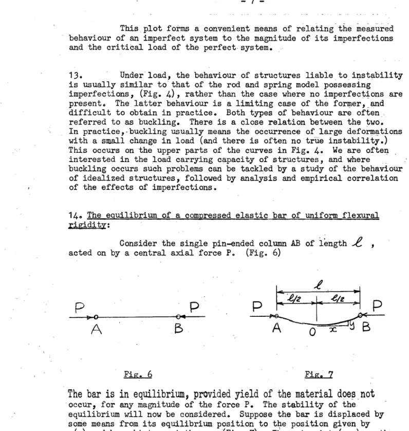
14. The equilibrium of a compressed elastic bar of uniform flexural rigidity:
Consider the single pin-ended column AB of length
,e
acted on by a central axial force P. (Fig. 6)P
A
_-
Fig ._6
Fig. 7The bar is in equilibrium, provided yield of the material does not
occur, for any magnitude of the force P. The stability of the
equilibrium will now be considered. Suppose the bar is displaced by some means from its equilibrium position to the position given by y(x) and brought to rest there. (Fig. 7). Then at point (x,y) on the displaced bar, the bending moment is
M = P(a y) = El d2y/ax2
(where El is the flexural rigidity of the bar), if the bar is in equilibrium in its displaced position.
Therefore d2y/dx2 + k2y = PA/BI where k = 152Ei
8
If the displaced curve is symmetrical about the line x = o, the boundary conditions
x = o, y = o, dy/dx = o give the solution
y = a(1 - cos kx) • •
Substituting the condition that y = a when x = 42 yields the equation a = a - a cos ki/2
This equation, which holds provided a is small, (otherwise the moment curvature relation is in error), is independent of the magnitude of a. It gives
ki/2 = 77/2, 317/2, 517/2, •
or P = 2E1/ 44.2 , 917 2E1/ 4? 2 , 25 172E1/4e 2 ,
If the displaced form is assumed to be antisymmetrical about o, (when x = o, y = o and d2y/dx2 = o and hence a = o), we obtain
y = A sin kx
Substituting the condition that y = o when x = 8/2 yields
ki/2
=.7i, 217, 317, ....or P = 41T2EI/E2, 161T2EI/12,
and the solution is independent of the value of A. We have therefore, for equilibrium of the bar in the displaced state,
P = n2)7 2EI/e 2 .. (10)
where n = 1, 2, 3, -
The bar is in equilibrium in the corresponding bent form as well as in the straight form when any of these loads are acting, and the magnitude of the displacement is unimportant, provided it is small. . The shape of the displacement curve is determined by equation (8) or
-9-
15. Critical loads and characteristic modes of distortion of a column of uniform flexural rigidity:
(See R. V. Southwell nTheory of Elasticity p. 424).
Consider the initially straight pin-ended strut shown in Fig. 8.
Ae
p
FiZe 8The strut is assumed to be displaced into some curve y(x). For equilibrium in this position, as well as in the initial straight configuration, the bending moment curvature relation yields
El d2 y/dx2 + Py = 0 • • (i1)
This is satisfied by y = A n in nirx/i, which gives, on substitution,
P = n2 II- 2EI/E 2 .. (12)
Pn.is the nth critical load at which neutral static equilibrium exists, and the associated mode of distortion is y = A n sin niTxa l
where the value of An is unrestricted. This value of y defines the nth characteriqic mode of distortion. The smallest value of
p
n
isp
1
11-2EI/e4, when the strut assumes the form y = Al sin Trxa.This value of P is called the first Euler load of the strut. At values of P n higher than P 11 the strut is in neutral equilibrium when displaced into its corresponding mode, but it is in unstable
. equilibrium when displaced into any other shape. Hence to achieve values of P higher than P1 1 restraint o1 some form is necessary.
16. The uniform strut from the standpoint of energy.
As in the case of the rod and spring mechanism
previously discussed, energy methods can be used to determine
the critical loads of the uniform strut.We have, (equation 11), El d2y/dx2 4' Py = 0.
i
Hence 2 /6[2)2 dx = .4 P .r y (d2y/dx2) dx.
o
1
oi
= i Pl(dy/dx)2 dx -
i
PET
dy/dxjo o
on integrating by parts. So long as either y or dy/dx vanish at o and
t
, we have Ai
rt
, 2 f-A-J
o
Ei(d
2
y/dx
4
) dx = i
P io (dy/dx)
2
dx .. (13) The term on the left is recognizable as the strain energy of
bending, and that on the right as the work done by the load when the bar assumes the bent position y(x).-
Hence J iEI(d2y/dx2) 2 dx P = N(dy/dx) 2 dx
-10-
where y represents the characteristic mode of distortion. In practice, closely approximate values of P can be found by assuming values of y which fit the given boundary conditions, and the energy method becomes a powerful means of obtaining approximate values of the critical load. The above is known as Rayleigh's . method.
If equation (11) is multiplied through by(y/EI)dx and integrated we obtain
ti
J Y(d2 yx x - /d 2)d 2d /EI - -P Yx 0
ri
-J
y(d2y/dx2 ) dx therefore P = 0.1
y2 dx/ 00 (15)This equation can be given a complementary energy interpretation. It is derived by Westergaard using the methods of complementary
energy, and he shows that it is also valuable in determining approximate critical loads using assumed forms for y(x).
Since d2y/dx:2 = -Py/EI, equation (13) can be rewritten as
El (Py/EI) 2 dx = P (dy/dx) 2 dx
r.
or
P = (dy/dx) 2 dxf
°17
3r2dx/EiFor approximate calculations this is better to handle than equation (14). Equation (16) can be reduced to equation
(15)
on integration by parts, provided either y or dy/dx vanish at o andWhen using such approximate methods for the evaluation of critical loads, it is best to consider those having relevance in terms of strain or complementary energy as particular cases of a family of methods which can be obtained by manipulation of equation (11).
For a treatment of Rayleigh's principle, see R. V. Southwell "Theory of Elasticity" pp. 442 - 455. In Southwell's book Rayleigh's method of calculation of critical loads or vibration frequencies is presented without prior reference to the principle of conservation of energy. The mathematics of the member behaviour is carried out first, and then given an energy interpretation provided certain boundary conditions hold; and these conditions fit the energy picture. The method is due to Lord Rayleigh (Theory of Sound Vol. I) and is
clearly presented in Temple G. and Bickley W.G. "Rayleigh's Principle" 0.11 P. (1933). Here again the principle of conservation of energy is not used. In the case of a harmonic vibration it is shown that the average kinetic energy equals the average potential energy, whereas conservation of energy equates the corresponding maximum values. The final equations are, of course, the same. The energy discussion in Art. 8 is drawn from this book.
• • . • ( 1 6)
The complementary energy approximate method of calculation of critical loads given above, is drawn from H. M. Westergaard "On the Method of Complementary Energy", Proc. A.S.C.E. Vol. 67, No. 2, p.199 1 Feb. 1941. The same equation is derived by Westergaard using complementary energy conceptions, but in this thesis it is derived mathematically from the column equation, and can be given Westergaard's complementary energy interpretation if desired. It should be noted that equation (16) is reducible to equation (15) only if the given boundary conditions hold. These are not mentioned in Westergaard's paper, and this omission may cause confusion. In
certain cases Westergaard has shown that equation (15) gives a closer approximation to the critical load than equations (16) or
(14).
Other useful approximate methods are given in S. Timoshenko "Theory of Elastic Stability" (1935) McGraw Hill p.81 1 but Rayleigh's method has been widely used: an interesting example is the calculation of the critical load of an unbraced arch rib when buckling out of its plane occurs: "The Lateral Buckling of Tied Arches", W. G. Godden, Proc. I.C.E., Aug. 1954, Vol. 3 1 No. 2, p. 496. The power of Rayleigh's method is also illustrated in a discussion by the author on a paper by
R. Frisch Fay "The Buckling of Struts of Varying Cross-Sections" Journal I.E. Aust. Vol. 31 No.
3
Mar.1959 p. 81.
In the original paper Bessel functions are used to solve the problems, but the author has shown that the approximate solution obtained very simply by Rayleigh's method is very close. This gives a guide to theaccuracy of Rayleighls method where no standard solution
is available for comparison. See M. Gregory, discussion on the above paper, Journal I.E. Aust. Vol. 32 1 No. 9, Sept. 1959, p.231.17. The vibrations of a compressed bar:
Assume
the bar is of massf per unit length and vibrates in the formy = a sin(firx/4?) sin cot;' (See Fig,: 9)
Fin. 9
Then, applying the same method as was used in the case of the rod
and spring mechanism, the value of ot.) can be calculated. The total
kinetic energy when 'y = o is/2 dx
a) 2
a2 sin2(Tr 20! )
0
=
*00
2
ria
2.When y reaches its extremum, the energy given up by the load is
P
f y/ax)2 dx= P 1T 2a2 P / 4 ‘o )
Fig. 10 OC
If the centre line of the strut under load P is given by y(x), the bending,moment at x is
- 12 -
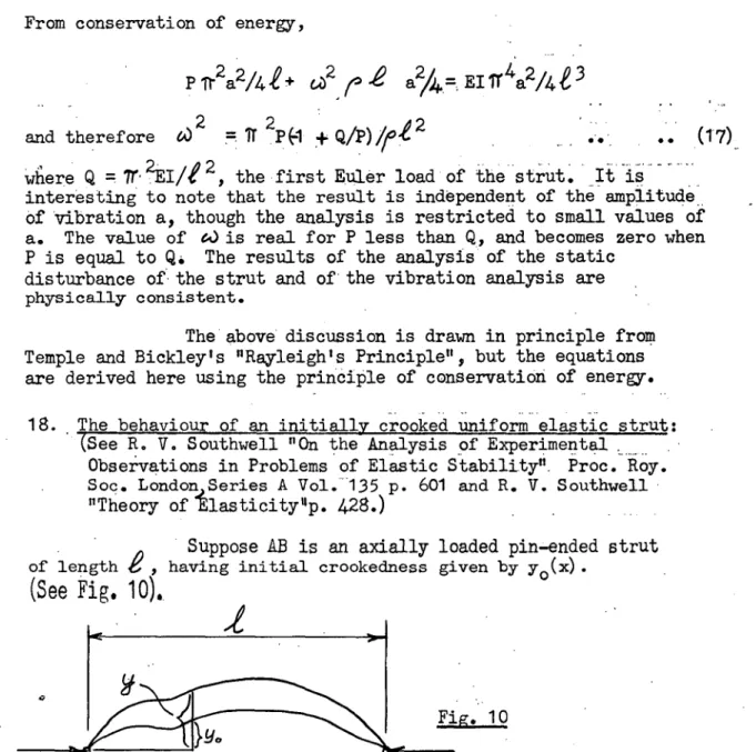
From conservation of energy,
2 2, 2 2 / ir
4 2/
t3
P Tr a /4 + 64) a /4=. El a 42 2 , \
and therefore 64) = PO ±Q/pur-
wfiere Q = 77' 2:EI/i 2 , the first Euler load of the strut. It is
interesting to note that the result is independent of the amplitude_ Of Vibration a, though the analysis is restricted to small values of a. The value of A) is real for P less than Q., and becomes zero when P is equal to Q. The results of the analysis of the static
disturbance of the strut and of the vibration analysis are physically consistent.
The above discussion is drawn in principle from Temple and Bickley's "Rayleigh's Principle", but the equations are derived here using the principle of conservation of energy.
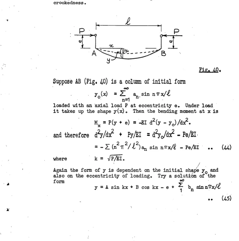
18. The behaviour of an initially crooked uniform elastic strut:
(See R. V. Southwell "On the Analysis of Experimental Observations in Problems of Elastic Stability". Proc. Roy.
Soc. London Series A Vol. 135 p. 601 and R. V. Southwell
"Theory ofIlasticityup. 428.)
• Suppose AB is an axially loaded pin-ended strut
of length having initial crookedness given by y o (x).
(See Fig. 10).
M = Py:
and we have Py = -El d2 (y-Y0)/dx = -El d2y /dx El d2y0/dx2 . therefore d2y/ax2 omK41 d2y0/dx2 .. (18) The form of y(x) is thus dependent on the form of yo(x).
zoo
=1i an sin n IT
agsuming yo to have any form between A and B and provided yo and eyo/dx4 both vanish at x = o, £.
Equation (1 8) is satisfied by
y = b sin nil x/i 1 n
and substitution gives
[ 2 - n in2
1 nit k2b ] sin nil' xie
5 - n2 1r an/e sin niix/4? 1
'Put
7
.#
- 13 - where k = 1
5,7EF
This applies for all x. Therefore
Now
(bn
_
an) n
2
T;
2
/
e 2 =
k
2
bn
bn
= a
n
/(i _
k
q2
/n
2
Tr
2
)
Tr 2EI/e = Q, the first Euler load of the strut
.. (19)
and therefore bn/an = (1 - P/n2Q) -1 , giving the ratio in which the the initial shape
an sin nicx/e is magnified by the end thrust. Now as P approaches C4 - b1 /a.1 = (1 - .0
..
(20)and a1 is greatly magnified, since
lim
(1 _pA)
-l =
00.
P = Q
1\ -1
Also b2/a2 =
(1 -
47 = 4/3
)
9
when P = b3/a3 = (1 - 1/9) -1 = 9/8 when P = Q . The central deflection of the strut isb = bl - b3 + b5 - b7 +
and as P approaches Q, the terms after b1 can be neglected. Hence b = b1 = a
1
/(1 - P/4)
provided equation (18) is applicable, that is the curvature is small and yield does not occur. The behaviour is thus similar to that of the
initially out.of line rod and spring mechanism. Deflection of
the strut occurs as soon as P has a value, and becomes very large asP
approaches first critical load Q =Tr
2
E14
2
19. The measured central deflection is = b - (the central value of Yo)
a1
= _
pA) -
al
This reduces to
= + •• .. (21)
Now &A
1
is constant for a given strut ) so the graph
6/F
against
is
astraight
line of slope 1A and intercept on the 8/1 )
axis of
a1 /4. (Fig. 11)
- 14 -
I0
P
/Q
S/
p
0
Fig. 11. The behaviour of the initially crooked strut is thus a function of its
initial crookedness and of the critical load of the perfectly straight
member. The linear plot, (equation,21 and Fig. 11) is a valuable means of empirically relating the behaviour of the member possessing practical imperfections to that of the perfect member, and is due to Southwell. The plot is often called the Southwell Plot on deflections. It was introduced in the first place as a means of inferring the first Euler load of a strut from measurements of deflections taken during loading, but the implications are much more far reaching.
20. The behaviour of .a column subject to compression P and bending
moments at its ends:
Columns in structures are never
pinned at their ends, but
fixed in some way to other members of the
structure.
Often the .joints are quite rigid. Rotation of the end of a column is therefoi-erestrained by the other members framing into the joint, and any _ rotation c.D111.s into play end moments. To discuss the buckling of frames consisting of an assemblage of members, it is convenient to analyse first
the behaviour of a single column subject to end
moments.21. Consider the initially straight bar AB acted on by an axial load P and end moments MA and MB, anticlockwise moments and slopes being considered positive. (Fig. 12).
Fig. 12 At the point x, the bending moment is
M = MA - (MA 4' MB) X/.€ + Py = -El d 2y/dx2 , which gives the differential equation
d2y/dx2
PY/EI =
41
A (1 - x/e)/P + MB
x/EI)?
Putting P/EI = k
2
, the solulion can be written
-y.
=- A
sin"Q kx + B abb'kx - MA (1 - 0:)/I+ MB x/PAe
Substituting the boundary conditions
x =
y = o and x =,e 1 y = o l
we have
B = MA/P and A = -(MA/P)cot 0
2
,-(14B/P) cosec
k,e
-15 -
Now dy/dx = Ak cos kx - Bk sin kx + (MA -1- MB)/Pi. Putting x = o, the slope at A is given by
EIq =
,,,,Ae(3/3 _ mB ic0,6
.. • •
(22) where 04 = (6/k2 2 ) (la cosec 14- 1) ))and = (3/k2 ,e 2 ) (1 - kicot 14) ) •• (23) and k = FTE1 .
The treatment given here is similar to that given in Niles and Newell "Airplane Structures" Vol. 2 (Wiley) but is believed to be simpler. In this book the oe and (3 functions are derived in connection with the three moment equation for two adjacent struts. Equation (22) is simpler.
22. Bending of a bar subject to tension T and bending moments applied at its ends.
In this case we have
El
O
A
= MA I(V3 - N4eocA • . .. (24)where owe =
(6/4
,e
?) (1 _ kl icosech
k -4? ) )1 1 )
) °. .. (25) (., = (3/14 4? 2) (ki6oth klAe - 1 ) )
and k
1
=417E .
The functions oe =di.; for axial compression and
-e
and fi for 1 1 axial tension are tabulated on pages 72 and 107 of Niles and Newell"Airplane Structures" Vol. II, 3rd ed., 1948, (Wiley).
23. The behaviour of a column fixed at one end.
Consider the column AB which is fixed at A and pinned at B (Fig. 13)0
and
Fig. 13
Suppose a bending moment MB is applied at B. This causes a
deflection of the column as shown in the figure, and a bending moment MA at A. arises. Then we have
El 0A = M .A 1 /3 MB 4?0(
/6,
and EI OB = MB i(3 ./3 - id /6.
A
Mo
OBD Fig. 15
eez
-16 -
Now since = o, we have
MA = (G.e/2( ) MB.
and thevare MB/ 61/3 4 (3 Eii,e (4/52 .... e4 2)
mo9
B
represents the stiffness of the end B against The graph of MA/d9B against ke is shown in Fig. 14. for values ofke up
to 4.495, becoming zero at this corresponds toP = k2EI = 20.2 EI/e.
0 0 .. ( 26) an applied moment.
It is positive value, which
When MB/aR becomes zero, a vanishingly small applied moment causes a large rotaIion, and this gives the buckling load of the member.
NAB/efs
Fig. 14
24. The procedure can be given an energy interpretation. The work done by the applied moment is MOB since MB andaB are linearly related for any given values of P (Equation 26).
The strut has not become unstable provided positive energy is required to deform it. The condition for stability is thus 'v. MOB is positive. At neutral equilibrium - MBOB is zero, and the expression becomes
negative when the equilibrium is unstable. These criteria are consistent with those for stiffness given above, as they reduce to MBA positive zero or negative.
25. The buckling of a simple frame.
Consider the simple plane frame shown
in Fig. 15. The
joint B is assumed to be rigid and the members have the same
length
and flexural rigidity.P)
P)
To find the load P to cause buckling in the plane of the frame, a distorted form such as that shown is assumed. To cause the
- 17 -
9
•EIOB = EIi9BA = MBA40/3 • = EI
=
MBD e/3= EI OBc = MBC1(4 /3
Also MBA MBD. MBC = Mo, ,where MBA is the moment that arises at B in the member
BA,
etc.Therefore . (3EI/i)
PBA43 6)
Bp 6BC/(5
1 - whidlgives 14044 = 3(2/(5 + 1).The stiffness is therefore zero when (3= -2, and this occurs at k =
3.5
or P = 12.3 EI/-e2.26.
Principles useful in the calculation of the buckling loads of more complicated frames can be illustrated by reference to the frame shown in Fig. 16.Fig. 16
ik‘
P
The members are of equal length and flexural rigidity and the end D is fixed.
We have EI0B=EIOBA = MBA
'P/
3
,
= EI °BD = MBD
"873
- MDB=EIOBc=Mgcle/3
Also El
ODB=
MDBE13
- MB 1/6 = 0 .. (28)and MpA MBD MBC = Mo • • .. (29)
if an external moment Mo is applied at the joint B. Clockwise
moments and rotations are considered positive.
Equation (28) gives MDB = MBD•
Hence equations (27) and (29) give
- 18 -
The stiffness of the joint is zero when
m
o
/e9B = 0,
or = -3/2. This is the buckling condition, and yields k = 3.6, or P = 13.0 El/I2.
27. Alternatively, we may treat the behaviour as an eigenvalue problem. We have, putting M o equal to zero,
MBA MBD MBC = °
BA - -BC 0
MBA - 3MBD/4= 0
These three equations, being linear and homogeneous in the three unknowns MBA , MBD and NBC, have in general only the zero
solutions MBA= MBD = MBC as = 0 (in which case all the end rotations are zero and the structure has not altered shape), unless the determinant of the coefficients is zero. In this case the equations are not independent and there is insufficient
information to solve for the unknowns, which are therefore undefined.
Putting
1 1 1
1 0 —1
0
we obtain
p= -6/4
which is the
same condition as given above. The interpretation is
that when the moments are undefined, then the linearly related end slopes are undefined and the system has buckled.
For a discussion of eigenvalue problems see Biezeno and Grammel "Engineering Dynamics" Vol. 1 (Blackie) p. 183, also Courant and Hilbert "Methods of Mathematical Physics" Vol. 1
(Interscience Publishers).
28. It will also be shown that at the buckling load the ratio of some internal bending moment to an externally applied disturbing moment M o becomes infinite.
We have MBA MHD NBC = Mo. • MBA - MBC
PmBA — 3M
BD/4 These give 2MBA MBD = Mo=0 .
= 0 .
Therefore (6/4 I) MBD = -1 and
MB
D
4q
o
'='(6/4( 1) The ratio becomes infinite when= -3/2, which is the same condition as
4
- 19 -
29. We have therefore three conditions or methods for obtaining the buckling load of the frame in the mode
considered. They are
(i) the stiffness of a joint to an applied disturbing moment becomes zero ( or the energy required to rotate the joint becomes zero.)
(ii) the determinant of the coefficients in the equations in the bending moments is zero. (Similar equations in the deformations of the system, e.g. the end slopes of the members, can be handled in the same way.)
(iii) an applied disturbing moment causes an infinite interRal moment in some member of the frame.
It is to be noted that the methods are
mathematically equivalent once the desired buckling mode has been decided on. Various techniques are available for solving the equations, which become numerous and lengthy where a frame contains more than a few members even if these all lie in one plane. These techniques will be illustrated by referring to the buckling of a triangular frame.
30. The Buckling of an Equilateral Triangular Frame in its Plane. One of the simplest frames is a triangle, and the buckling of an equilateral triangular frame having initially straight equal members will be considered. It is assumed that the frame is made up without any internal stresses being set up.
Buckling in the plane of the frame without tension of the members can be ensured by placing the minor axis. of inertia of the cross- section of the members so that it lies in the direction perpendicular to the plane of the frame.
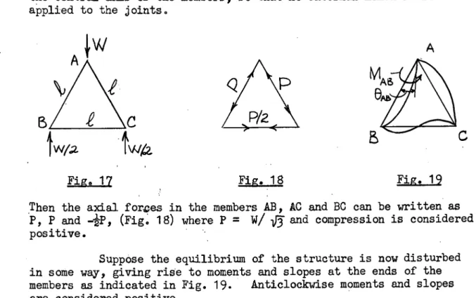
Suppose the frame ABC is loaded in its plane as in Fig. 17, the applied forces passing through the intersections of the central axes of the members, so that no external moments are applied to the joints.
Fige 17 Fig. 18 Fig. 19
Then the axial forces in the members AB, AC and BC can be written as P, P and (Fig. 18) where P = W/ -if5 and compression is considered positive.
Then we have
and
-20-
))
Me
Ab_
=
MAB 3 /6El
O
BA
= NBA /fi/3 2°( /6 )) ElO
Bc
= MBc4/3
_ McB-E.(
/6 )) EI cB = NCB/P - NBC"
1
/6 )EIOCA =
McAifi/3
MAC 4( )) EI eAc MAC 4/3MCA
"e°( /6 )• • .. (30)
where eeand
P.
refer t9 members of length ihaving axial compressive load PI andc4i and r:31 refer to a member of length I. having axialtension P/2. For continuity at the corners,
°
AB =q110' °BA = 8B0P and ° GB =6ICA°
Also, since there are no external moments at the jointsN
AB + NAC = 0, MBA mBC = MCB + MCA = °.mAB = Ni =
NAL
N
BC = MB = MBAMCA =
= - mul
q mit + ot mB +01, mc
=0
+ 2((3 +(1 .1 ) mB Got =0
4,14A +comB r&I ) = 0
At the buckling load, MA, MB, and Mc are undefined. e4 c4 2 (6 + ) I
2(( + (13') This determinant, on expanding and factorising, gives
(213 + 2(3 1 -
04') [2((2( + 2( + o(1 ) -ce]
= o
(3,)
There are two modes of buckling. The symmetrical mode, (Fig. 20a) is obtained by putting the second factor equal to zero, and gives
ki =5.0 or P = 25 EIg2.
The unsymmetrical mode, (Fig. 20b), which occurs at a lower load is obtained by putting the first factor equal to zero, and gives
= 4.0 or P = 16 EIM9.2.
at
should be remembered that if k =15
)
7E, then113/TEI
equals k/i/I. 0.4! and(3
are thus functions of kiP „ for axial compression whiledi,' and r
si
are functions of ki/a for axial tension). Hence, puttingwe
have
Therefore
= 0
.- 21 -
Fig. 20
In the above analysis for the triangular frame, all the equations have been written down. From considerations of symmetry or
antisymmetry, this is in this case (and usually) unnecessary. The full treatment is given here because in certain cases,
notably when dealing with problems of buckling out of the plane, the simplifications available from symmetry considerations are often rather difficult to handle.
31. It is interesting to note that the solution for the unsymmetrical mode of buckling can be obtained by applying a small external moment at one of the joints. Consider the triangle ABC loaded as in Fig. 21. A small moment M o is applied to the joint A so as to bend the frame into the shape shown.
If\14
t
W/2 W/2etc., Suppose the moments set up at the ends of the members are NAB,
and the corresponding end slopes (9a, etc. Then equations (30) still hold. However, in this case
NAB + MAC =M0.
M
BA NBC =0. andM
OB + MCA = 0.Fig. 21
Also, from the antisymmetry of the distorted shape,
e
BA = 8B0=
°
CB 61 CA/ and e AB e ACInspection of equations (30). then gives
M
BA = MCA =_
NBC = MOBand PIAB = 1110 = •
•
•. (32)
e
BA
= a BC and the second and fourth equations of (30) then giveMDA/M0 = (c ( /2)/( 2 f5 - 0( 1 ) .. (33) The frame buckles when a small applied moment M o produces an internal moment which tends to infinity, or MBA/4Q tends to infinity. Hence, at the buckling load,
applted moment
M = 100 AB AC
EA SC 25
-O 50 - (4.
22
which is the same condition as we obtained previously.
The solution is unaltered by putting Mo equal to zero in the equations (32).
This gives MAB = MAC = ° We then have, from
0
0BA = BC 1
MBA (2
(3+ 2r 1 - 0( 1 ) =0, If 2r; + 2(5 1 - = 0,MBA is undefined, and a vanishingly small disturbance has resulted in buckling.
32. The unsymmetrical buckling mode can also be solved by using the moment distribution convergence criterion. This method is valuable in determining the critical loads of more complicated frames. The solution of this problem is carried out here as an illustration. The method is merely the solution of equation (33) by moment distribution. So long as the process converges, MBA/M, is finite. At or above the buckling load, MLiA/M0 is infinite and the Process of moment distribution diverges.
For a discussion of the moment distribution
convergence criterion, see N. J. Hoff "The Analysis of Structures" (Wiley) pp. 294 - 318. The unified treatment given in this thesis of the calculation of critical loads by all methods is, however,
believed to be original.
33. Consider first the frame ABC with no external forces acting, so that the axial forces in the members are zero. A small moment of 100 units is applied at A. In this case, all
carry over and distribution factors are equal to 0.5 and the moment distribution is as follows .
+3 +-
Fig. 22.
The final bending moment diagram is $0,
-23-
Fig. 23
This can be checked, since
El 8BA = MBA 2
/3
- NAB /61
= EII9Bc = MBC -E/6 . -4g/3 MCB
But M
BA
NBC = 0 and MK = MOB Therefore M =MAB /3 BAIf N
AB
= 502 MBA =Where there is an axial force in a member, the carry over and distribution factors must be adjusted accordingly.
Consider a bar AB subject to axial force P and bending moments MA and MB .
Then
ê
A = MA M6/3EI - MB -goe/6EI and6113
=N
B
ip/3EI _
NA /6E1. If rotation is not allowed at ByO
B
= 0
and MB = MAo4/2(3
For an applied moment MA at A, the carry over to B, if rotation is not allowed there, is oirMk/2(3. The rotation at A is given by
El
OA
=M
IL iV3 - MA 0( 2/12(3=
MA(E/3) (-0( 2/
4
)
=
NA (64) (4P 2
-0( 2)/3(3 .
Consider a number 5 members 1, 2,
3,
etc., meeting at
a
joint, (Fig. 24), their far endsaevented from rotating. Suppose
a moment
M applied to thejoint causes rotation
0.
If
the moments induced in the individual members are M etc., then2 2 =(4EI1/11)(3-1 )/(4(31 -0(1
0.385
1.223 1223
(b)
0•2
G
0.74 074 (c)
0•385 0.26
24
Fig. 24
Therefore
and
o
- a 2" (IM)
3/(40.0(2)=
M (Iitei)[3(;1/(4 2.1 -0(12)(1/e)
3p
/(11132 -(42)These stiffnesses and carry-over factors are tabulated on pages 122 and 125 of Niles and Newell "Airplane Structures", Vol. ii, for both axial compression and axial tension.
The moment distribution for the triangle loaded as in Fig. 25 can now be proceeded with.
0.365
0.386 0-S Ao5Fia. 25
Put
(ci) .0 =
3.8; that is P = (3.8)
2
EI/i
2
Then the G and (3 functions, and the carry over stiffness factors
are as in the table:
Member Thrust k -e a( 01/2/3 4 •
5r3
,k2
AB P 3.8 -2.9961 -0.8128 1.843 0.3850 AC P 3.8 -2.9961 -0.8128 1.843 0.3850 BC —P/2 2.7
0.533
0.716 0.3685
1.223Stiffness and distribution factors are shown in Figs. 25b and 25c. The distribution of an external moment of 100 units applied at joint A is carried out in Fig. 26. Only half the calculation is shown, as the distribution is symmetrical. Fig. 27 shows the resulting bending moment diagram. Comparison with Fig. 23 showS that large bending moments are induced in the frame as the buckling load is approached.
+2-
ABI AC
100 50 50 -44 4-
SO SO
Fig. 26
M4A
summed BA 92
68 - 68
81 -2 0•26
B
c
,
0
.
e CIN, -vs -39 0-741 0-37
1-44 1%3 - -Z1
+24 - 9
203 - 4 - 11
+.13 -4 -2 -
22e
222.
+222 +222
214
BC
The accuracy of the distribution may be checked by substitution in equation (33). •
We have
mBilmo =
(d/2)/(2p- ct )
= 2.21 fora =
3.8In this case Mo = 100
therefore MBA= 221. This agrees with Fig. 26. In this case, the distribution has converged, and the buckling condition is therefore(02)AB ,>3.8. However, induced moments are large, and the buckling load is being approached.
Put (k/)AB = 4.0
Then the carry-over and stiffness factors for the members are:
Member
a
.1/2
3132' ,.2
11.(1
- aAB 4. 0 2.56 • 0.293
Ac 4.9 2.56 0.293
BC - 2.81 0.362 1.238
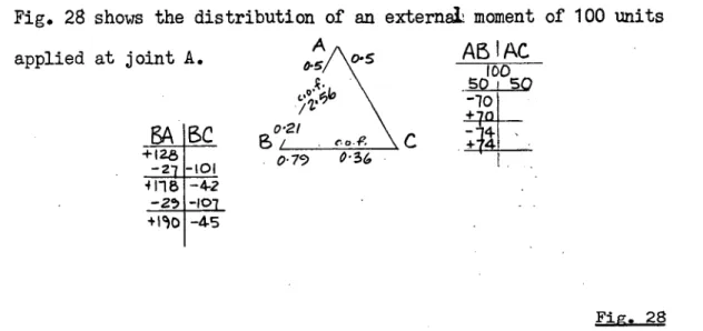
applied at joint A.
ABC
0.21
-21 -101 0.79 0 36 4118 -4-2
-29 -101 +190 -4-5
A
as
ABIAC
100SO SQ
"10
- 26 -
Fig. 28 shows the distribution of an
external
moment of 100 unitsFig, 28
This distribution is diverging, so the buckling load has been reached (or passed) at k.e = 4.0.
The two solutions to equation (31) for the two buckling modes were checked by experiments with a model made of flexible strip, and resulted in good agreement. It is also possible to calculate the higher critical load for the symmetrical buckling mode by the determinant method as in Art. 30 or by imposing the required distortion pattern as in Art.
31" .
The application of suitable disturbing moments consisting of equal moments of opposite sign at B and C I also permits solution by the moment distribution convergence method. However, it appears that in the case of more complicated frames, unless some sort of symmetry or anti-symmetry can be preserved, considerble care is required in the calculation by the moment distribution method of higher critical loads for buckling modes other than the fundamental. Even if a suitable disturbance is given, slight errors in distribution might well cause divergence at the first critical load.
It should be noted that the calculation of higher critical loads is not always merely an academic problem. The pattern of imperfections throughout a structure may be such that at failure it deflects in a mode which does not correspond to the fundamental mode of the corresponding perfect structure.
34.
When the moment distribution method is used to find the first critical load for more complicated frames, it often becomes difficult to ascertain whether the process is convergingor diverging. The zero stiffness method proposed by H.G. Allen overcomes this difficulty in certain cases. Allen has contributed two valuable papers on the calculation of critical loads using the zero stiffness conception: "The Estimation of the Critical
Load
of a braced Framework" Proc. Roy. Soc. London Series
AVol. 231
(1955) p. 25, and "The Estimation of the Critical Loads of Certain
Frameworks" The Struct. Engnr. Vol.35,
No. 4, April,1957,
p. 135. In his first paper Allen uses the conception of positive energy being required to displace a stable structure. In the second paper the emphasis is placed on stiffness, and it is also shown that his procedure of successive reduction of triangular frames to single members of equivalent stiffness is mathematically equivalent to reducing the determinant.- 27 -
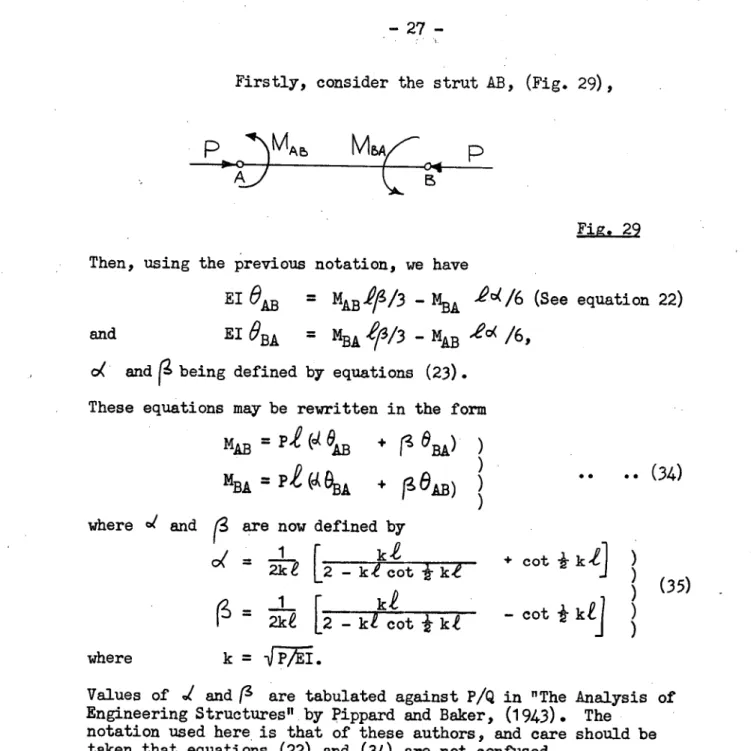
Firstly, consider the strut AB, (Fig. 29),
p DMAE,
MBAC p
Fig. 29 Then, using the previous notation, we have
El eAB = MABIP/3 - MBA 40(/6 (See equation 22)
and
El
61T1 A DA=
M
BA
1
/3/3
MAD '62( /6,o( and ig being defined by equations (23). These equations may be rewritten in the form
MAD = Pi °AB
eBA) )
)mBA
= ge
i
BA
rAkB)
.. (34
)A
where d and (3 are now defined by
1 k
= 2ke [2 — ke cot
r
ki
= 2kt L2 - kt cot k
kt
k = PAL
where
+ cot )
) (35) .
— cot k
Values of ./ and (3 are tabulated against P/Q in "The Analysis of Engineering Structures" by Pippard and Baker, (1943). The
notation used here is that of these authors, and care should be taken that equations (22) and (34) are not confused.
Equations (34) can be rewritten
MAD
AB
AB ABe
AB BA ).v
/-) )
M = U
+ V
r)
BA BA
e
BA BA AB (
..
(36)
where
AB = U
BA
= P
)
2 0(
V =
AB VBA = P /erg
)
)
) • •
(3
7)Consider the triangle ABC loaded in its plant (Fig. 30) 0
where the members are subjected to axial loads.
- V2.* + U )
AC CA
CB
-
42AC
AU
CA
+ UCB )
)
)
)
)
). (39)
)
where Ul = U. +U.
AB
AC
= U
BA
+ U
BC
BA
I..7 1. 4.7 P/Q-
I•4-7 1.47
4.")*)
Fig. 31 (b)
(a)
a
Vs1/2
-.28-
Now suppose disturbing moments MA and MB are applied at the joints A and B. We then have
MA = MAB MAC.
MB = MBA MBC °
MCA NCB = 0 7
Now NAB = UAB
e
AB •
+ VAB 913AMAC = UAC AC + vAC 9 CA
and
9AB
= 61AC
= t9A•Similar equations apply at the other joints. Elimination of Oc throughout gives
MA = 111ABA + V'ABOB )
and MB = UIBA B VIBA A ) ) e
(3
8)and V'
AB = V'BA = VAB - VAC VCB AUCA UCB)
The modified slope deflection equations (38) give the relationships between the moments MA and
MB
applied to the triangle ABC and the rotations ofthe
joints,OA
and
eB .
The triangle ABC can therefore be replaced by a hypothetical member A'B' of equal stiffness with respect to disturbing moments. Neutral equilibrium exists when MA /r0A is zero for zero MB. The condition for stability is that MITA-
is positive. From equations (38), ifM
B
is zero, we haveMAP9A = (UI AB VI AB V IBA)/11 IBA
The criterion for stability is therefore
UIAB IP BA Vt AB VIBA ° (40)
35. If the triangle ABC is loaded as shown in Fig. 31a,
the values of U and V are as in the table, if PA for the struts
- 2
9 -
Member Al.
ie
pA 0( (3 U=Pid 11%..-Pir3 AB strut 1 10 1.5 .098 .194 1.47 2.91AC strut 1 10 1.5 .098 .194 1.47 2.91 BC tie 1 10 0.75 .665 .244 4.99 1.83
The values of U and V for each member are shown in Fig. 31b, U values being written near the ends of the members and V values near the centres. The triangle ABC may now be replaced by a member A'B' of equal stiffness so far as disturbing moments are concerned. We have, using equations (39),
U'
AB = 1.47 utBA = 1.47
VIAB = VI BA = 2.91 - (2.91 + 1.83)&1.47 4. 4.99) = 2.09
The expression of the left of equation (40) has the value (1.62 x 5.94) - (2.09) 2 = 4.25.
This expression may be called the stability criterion. In this case it
is positive, and the frame is stable.
When P/Q has the value 1.6, the calculation is as follows
Member PA (3 U V
AB 1.6 .078 .189 1.24 3.02
AC 1.6 .078 .189 1.24 3.02
BC 0.8 .628 .227 5.00 1.82
/,
- (3.02)2 A1.24 + 5.00) = 1.02 - (1.82)2/(1.24 4. 5.00) = 5.71
VIAB = VIBA
= 3.02 - (3.02. x 1.82)7(1.24 5.00) = 2 , 14
Stability criterion = (1.02 x 5.71) - (2.14) 2 = 0.24. This is positive and the frame is stable.
For PA =.1.71 we have
Member PA 0( U v
AB =
AC
BC
167
0.85
.058
.599
.184
.213
0099
5.09
3.13
1.81 + 1.47 - (2.91) 2/(1.47 + 4.99) = 1.62 + 4.99 - (1.83)2/(1.47 + 4.99) = 5.94
UlAB
UI BA
=
=
1.24
1.24
Ul B = 0.99 + 0.99 - 0.13) / UlBA = 0.00 + 5.09 - (1.81) V'
AB = V'BA 3.13 - (3.13
Stability criterion
= (0.37 x 5.54) - (2.40) 2 ./ 2
/(0.99 + 5.09) 2
/(0.99 5.09) = 5.54 1.81)/(0.99 + 5.09) = 2.40 = 0.37
= - 3.7. This is negative
1'6
I. 7
P/Q
- 30 -and the critical load has been exceeded.
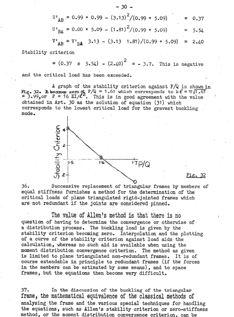
A graph of the stability criterion against P/Q is shown in
Fig. 32. Lbecanes zero ats = 1.61 which corresponds to ke = .61
= 3.99,or P = 16 EI/I'. This is in good agreement with the value obtained in Art. 30 as the solution of equation (31) which
corresponds to the lowest critical load for the gravest buckling mode.
Fig. 32 36. Successive replacement of triangular frames by members of equal stiffness furnishes a method for the determination of the . critical loads of plane triangulated rigid-jointed frames which are not redundant if the joints are considered pinned.
The value of Allen's method is that there is no
question of having to determine the convergence or otherwise of a distribution process. The buckling load is given by the
stability criterion becoming zero. Interpolation and the plotting of a curve of the stability criterion against load aids the
calculation, whereas no such aid is available when using the moment distribution convergence criterion. The method as given is limited to plane triangulated non-redundant frames. It is of course extendable in principle to redundant frames (if the forces in the members can be estimated by some means), and to space frames, but the equations then become very difficult.
37. In the discussion of the buckling of the triangular
frame, the mathematical equivalence of the classical methods of
analysing the frame and the various special techniques for handling the equations, such as Allen's stability criterion or zero-stiffness method, or the moment distribution convergence criterion, can be clearly seen. The methods all depend on the properties of linear equations where the coefficients are functions of the applied loading.
tt
-4
ue.
- 31 -
38. It is worth mentioning that when considering any structure, we are concerned with the stability or instability of the structure as a whole. Though compression members or elements must be present for buckling to occur, the critical load and the associated mode are dependent on the properties of the whole of the frame and its loading. This is still the case for practical frames under load. 39. The buckling of a Warren truss in its plane.
As an example of the application of various methods of calculation of critical loads of plane triangulated frames, the buckling of a Warren truss will be considered. The classical method will first be used to determine the buckling mode.
LW
A—(31,, Q
C
W I tV\I
Fig. 33The truss, when loaded as in Fig. 33, may buckle in various modes, but the critical load for the symmetrical mode shown will be
calculated. The forces in the members are given in the figure, and all members have equal length and flexural rigidity. On applying a distortion of this form, we have
9
_e
B 1
°
EOD
= 0 . AThen
O A
= B = MAB (3 ABPi3EI - MBA ti AB 4E'
and
8 B 0 BA
= MBA (3 BA ii3EI - M 04 AB AB 4?-/6E I . Hence MBA = " KAB
The other equations of symmetry are easily written down. We then have, denoting the members by the numerals in the figure,
6E1 = 14,11B ( 2
1.1 °4
1 )6E1 9Ad)/1 = M
m
). 2
/8 1 - MDA 2 ),6EI eAEd = MAE 2 3 -M 3 ) ) Also from
6)
EA
= 6 ED'
MEA' - MAE c4 3 = M
ED
' 46:
4 MDE 44"and from DE r.
ODA
0,
MDE 26. - 1\4ED 0( 4 :0-•
= m . 2p m
D 2 AD 2oe
(40)