ALGOL W
ON A
BURROUQIS B6700 COMPUTER
by
Henry D. Meeld.n
A thesis presented in partial fulfilment of the requirement for the degree of
Master of Science in Computer Science
at
Massey University
of ALGOL Won a Burroughs B6700 computer, and was written so that excerpts can be made to produce a user manual and a system documentation manual. The first part is a brief discussion of the language as implemented and discusses the main fea.tui~es of the language and the differences from ALGOL 60. The remainder of the thesis gives a detailed descriptio:1 of the compiler.
In presenting this thesis I would like to take this opportunity to express my thanks to the following people:
To my supervisor, Lloyd Thomas, whose guidance and encouragement helped at all times.
To Neil James for helping with those niggling program errors.
To the Computer Unit operators, especially Colin Read, for performing their job so well in helping me run my program.
Finally to my family and the group, for their persistence in prodding me to finish.
Massey University Harry Meekin
May 1976
Chapter 1
Chapter 2
Chapter 3
Chapter t~
Chapter 5
BRIEF DESCRIPTION OF THE LANGUAGE 1,1 Data Types
1. 2 1. 3 1.4 1.5 1.6 1. 7
Statement Sequencing Procedures and Parameters Data Structures
Block Expressions Assert Statement Input/Output
GENERAL ORGANIZATION PASS ONE
3,1 Internal Pass One Tables 3.2 Pass One Output String
Representing the Source Program 3.3 Pass One Table Output
PASS TWO
4.1 The Parsing Algorithm 4.2 Error Recovery
4.3 Storage Allocation 4.4 Value Stack
4.5 4.6 4.7
Interpretation Rules Pass Two Tables Pass Two Output PASS THREE
5.1 5.2 5.3 5.4 5.5 5.6 5.7
B6700 Architecture
Program Structure in Memory Stack Operation
Example of Simple Stack Operation Syllable Format and Types
Addressing
Block and Procedure Entry
Chapter 6 REFERENCES APPENDICES
5.10 Subscripted Variables
5.11 Passing Sub-Arrays as Parameters 5.12 Operands
5.13 Branching
5.14 Record and Field Designators 5.15 Further Examples of Pass Two Tree
Output as Received by Pass Three SUMMARY
A Simple Precedence Grammar for Extended ALGOL W
B Full Description of Extended ALGOL W
C Compile-time Options D Error Messages
v.
58 60 61 62 63
1 2 3 4 5
6 7 8 9 10 11
Reserved Tables Identifier Tables Pass One Output Codes
Example of BLOCKLIST and NAMETABLE Format of NAMETABLE and Field Contents After Pass Two
Pass Two Output Vocabulary
~6700 Word Formats with Tag Mnemonics Object Program in Memory
Stack Arrangement Stack Operation Syllable Types
vi.
13 14 14 17
Chapter 0
INTRODUCTION
The language ALGOL W was first described in a report drafted
by Niklaus Wirth (hence the 'W'), asked for by IFIP Working Group 2.1 at its May meeting at Princeton, 1965. The report was distributed to members of the group as a "Proposal for a Report on a Successor of ALGOL 60" (1). However, at its October meeting, 1965, at Grenoble, the group decided the report did not represent a significant advance on ALGOL 60 so it was dropped as an official Working Document of the Group. Wirth then collaborated
with C.A.R. Hoare and revised and supplemented the draft. This revised report can be found in Wirth and Hoare [2].
Why then was it felt to be of sufficient interest to implement ALGOL W? ALGOL Wis similar in many aspects to ALGOL 60 but some concepts have been simplified and some extensions have been
introduced, The most important extension is the introduction in the language of the concept of generalised data structures. To supplement the array concept, which is virtually unchanged from ALGOL 60, there is a new data structure, the record ([3) and
[
4]).
This makes ALGOL W a more powerful language than ALGOL 60 in its ability to handle data structures and therefore a more suitable language for use in the commercial field.The language_ described by Wirth and Hoare, with a few changes (5], was first implemented on an IBM 360 at Stanford University (6)
in 1968.
In 1971 further revisions were made to the language at Stanford [7] and an improved implementation was developed. ALGOL W has since
This thesis describes an implementation of ALGOL Was revised in
1971, with some further modifications to be described in
subsequent chapters, on a Burroughs B6700 computer. Chapter 1
gives a brief description of the language as implemented. Subsequent chapters describe the organization in detail of the
compiler.
This thesis has been written so that excerpts may be made to
Chapter 1
BRIEF DESCRIPTION OF THE LANGUAGE
As the name suggests, a large part of the language is taken directly from ALGOL 60 [8]. As ALGOL 60 has been in extensive use for some time and is therefore fairly well known, this chapter will only discuss the major changes to ALGOL 60. A full
description of the Extended ALGOL W implemented by the author may be found in Appendix B.
1.1 Data Types
As is the case in most modern languages there has been an
increase in the number of primitive data types from the three in ALGOL 60. The types included in the language are integer, real, long real (double precision real), complex, long complex (double precision complex), logical (equivalent to ALGOL 60's boolean), bi ts, string, and reference. The ALGOL 60 concept of own variables has been dropped as it doesn't add any power to the language and leads to semantic ambiguities in many cases.
The type complex is internally represented as two real words, one for the real part of the complex value, and one for the
imaginary part. The type long complex is internally represented as two long real words with the same meanings as in the case of complex.
The type bits is one word containing a sequence (i.e. an ordered number of elements) of binary digits. Operations defined for bit sequences include the logical operations-,, A (and), and
V ( ~ ) , and those of shifting left (shl) and shifting right (shr).
explicitly stated, e.g.
string (10) A
declares a variable A which represents a character sequence of up to 10 characters. The string type is internally represented in an analogous way to the Burroughs Extended ALGOL EBCDIC
arrays. Originally the operations for string sequences included the catenation operator cat, but with the addition of the concept of substrings the cat operation was found to be redundant and so was abandoned.
The type reference will be discussed in section 1.4.
An interesting ana very useful aspect of the design of the
language is that the type and length of the result of evaluating every expression or subexpression can be uniquely determined at compile-time, so no type testing, except possibly on procedure entry, is needed
at
run-time, thereby not wasting execution process time for non-compatible type testing.With the increase in the number of data types there is a greater number of possible type conversions. Automatic type conversion
(i.e. conversion performed by the compiler) is confined only to cases where no confusion about the required conversion is possible, i .e. from integer to long real, and real to co~plex, and from shorter to longer variants of the types. All other conversions must be programmed explicitly by the programmer with the use of standard functions. This is so the programmer knows exactly what type of result he is getting rather than relying on a default conversion which he may only have vague or even mistaken ideas about.
1.2 Statement Sequencing
expressions, integer labels, and label parameters have all been abolished.
The switch declaration and switch designator have been replaced by the case statement and case expression. These allow the selection and execution (or evaluation) of one of a list of statements (or expressions) due to the value of an integer expression. As the case construction is in use in a number of modern languages and is fairly well known, the reader is referred to Appendix B for more detail if required.
A goto statement can not lead from outside into any if statement, case statement, or iterative statement.
There are three types of iterative statements:
{i) for<id>:=<for list>do<statement>,
(ii) for<id>:=<i.nt.exp.>step<int.exp.>until<int.exp,>do<statement>,
(iii) while<log. exp. >do<statement>.
These are the simple and most common cases of iterative statements and more complex cases can be easily dealt with by explicit program instructions using labels. There are a few points to notice. The <for list> and step-until parts can no longer be mixed. The "step <int.exp.>" is optional and if missing a default step of 1 is used. The <id>, called the control identifier, is implicitly declared at the start of the for statement and is undefined
outside the scope of the for statement. No explicit assignments are allowed to be made to the control identifier.
1.3 Procedures and Parameters
There are a few changes towards clarification and efficiency of implementation, to the ALGOL 60 concept of procedures.
explained in terms of the "copy rule". In addition to the
"name parameter" and "value parameter" there has been added the
concept of a "result parameter". This formal parameter, like
the value parameter, can be thought of as a local variable.
Upon the termination of the procedure the actual parameter, which must always be a variable, is assigned the value of the pseudo
formal parameter.
Array parameters can only be called by name.
An actual parameter may be a statement (or expression) providing the corresponding formal is procedure (or <simple type> procedure).
This statement (expression) is considered as a proper procedure body (function procedure body) without parameters. This enables a procedure (function) to be specified in the actual place it is to be used rather than in the head of an embracing block.
As mentioned in 1. 2, the label parameter has been abolished.
This results in no loss of power because the result of the old
label parameter can be achieved by writing a goto statement in
an actual parameter position as outlined in the preceding paragraph.
In this implementation the concept of virtual parameters has
been included. A programmer may optionally specify parameters of formal procedures and thus enable compile-time formal procedure
parameter checking. In the cases that this facility is used, no
run-time parameter checking is needed on procedure entry. This
concept is used extensively in ALGOL 68.
The specification of all formal parameters (except parameters of
formal procedures) and the correct matching of actuals to formals has been made compulsory. The number of dimensions of an array
parameter must also be shown. The specifications are included
in the formal parameter list rather than in a separate specification part as in ALGOL 60. This is a much tidier form of specification
1.4 Data Structures
The only changes to the ALGOL 60 array concept are notational. The type of the array must always be specified and only arrays of the same type and dimension may be contained in the same array declaration.
There has been a major addition of another type of :Iata structure, the record (4]. Like the array, records consist of one or more elements (called fields)> but unlike the array the fields do
- -. -
-not have to be of the same simple type, so that each field may occupy a different amount of storage. Because of this to select a particular field a computed ordinal number cannot be used. Each particular field is given a name (identifier) which is used in the program whenever that field is referred to. f,lso,
unlike arrays, records are created dynam~c~~ly
?Y
§~~trme~~~ in the program rather than by declarations (?~e Appe~d~x ~? ~~ction 6.6).The normal data types (see 1.1) are sufficient to r~present the
. . . -. - . . . -properties of the fields of records, but a new type, ~ference, is required to represent relationships between the r~~ords. for example, if a record which represents a person has a field
named "father", then this is likely to be .used to contain a refer•ence to the record which represents that p~rS?!J. '~ fat her.
References are also used to provide programmers access to records. For this purpose, variables of type reference should be declared in the head of an embracing block, e.g.
reference(<record class list>)<id list>.
The <record class list> is a list of the record classes to which the identifiers in the <id list> may refer. Thus reference variables are somewhat analogous to a restricted form of pointer variables.
have the same names and types. Each record class is introduced
in a program by a record class declaration which associates a
name with the class and specifies the names and types of the fields
of that class.
So that any particular field of a particular record of a record
class can be referred to, a field designator must have associated
with it a reference expression which is a reference to the required
record (see Appendix B, section 6.8).
compatibility at compile-time.
This is checked for
Because a reference variable may refer to more than one record
class, it is sometimes necessary to know at a particular part of
a program to which class the reference is then referring. To
achieve this knowledge there is ·a logical expression,
~eference primary>is~ecord class identifier>,
which is true if the reference primary is referring to a record
of
that record class and false otherwise.There is also a null reference, null, which points to no record,
i.e. if a reference has the value null it is undefined.
1. 5 Block Expressions
There has been the introduction of a typed block which is a block
that has a value (see Appendix B, section 6). The block acts
like a function procedure body with no parameters and is a useful
notational convenience because like the statement parameter, it
allows the function to be specified actually in the place where
used, rather than disjointly in the head of an embracing block.
1.6 Assert Statement
Puring the running of many programs it is useful to terminate
This is achieved by the use of the assert statement, assert <logical expression>,
(see Appendix B, section 5.1) which will terminate the program if the <logical expression> is not true.
1. 7 Input/Output
In the original implementation of the language input/output was achieved by the use of primitive standard procedures READ, READON, READCARD, WRITE, WRITEON, and IOCONTROL (7]. These procedures did not allow for programmer formatting. In 1971, the University of Manitoba developed format-directed input/output facilities for ALGOL H (9]. Upon study of these facilities it was found that they were not as versatile as those employed by Burroughs Extended ALGOL [10 and 11]. Because of this and because of the desire to make the implementation compatible
with the existing system on the Burroughs B6700, a slightly
simplified version of the input/output facilities used by Burroughs Extended ALGOL [12] was adopted. These facilities include the file statement, read statement, write statement, space statement, rewind statement , seek statement, close statement, and lock
Chapter 2
GENERAL ORGANI7.ATION
In writing this /~LGOL W compiler it was decided to follow the
original implementation and have three passes with the syntax
being checked by the use of a simple precedence matrix. This
decision was made because of the following reasons:
1. It was felt that to be most useful to programmers using ALGOL W, better and clearer diagnostics were needed than those able to be given by a one-pass compiler using r•ecursi ve descent.
2. ALGOL W was designed c1s a precedence grammar (one of the effects of this being the use of a double colon in ar1~ay declarations
array A( 0:: 6 ,O: : 6) ) •
3. It is planned at a later time to add debugging aids similar to those developed by Satterthwaite
[13],
and the three pass organization is best suited for this.The compiler is written in Burroughs Extended ALGOL and each pass
is represented by an internal procedure.
Pass One is the scanner of the source program.
the following:
(i) Reads the source program
It performs
(ii) Converts the symbols to an internal code to be passed to Pass Two with blanks and comments deleted
(iii )
(iv)
(v)
Converts numeric constants to internal machine form
Builds a block-structured nametable
Pass Two does the syntactic analysis of the source program as passed to it from Pass One. In most cases the analysis is performed by means of a simple precedence analyzer thus allowing extensive error checking. However, in the case of file
declarations and read/write statements the analysis is performed by recursive descent. This was done since these features are extensions to the language, and the conversion of their syntax to a simple precedence form was found to be difficult when these extensions were embedded in an already simple precedence ALGOL W grammar (see Appendix A). For these statements a simple precedence form would not add any great error checking ability anyway. Pass Two also completes the nametable and forms a binary t1~ee representing the parts of the source program for which code needs to be generated.
Chapter 3
PASS ONE
f>ass One reads the source program in 80 character records. It assigns coordinate numbers beginning at 1 as follows . The coordinate number is incremented once for each";" (except end-of-comment), begin or else. This number is used in error messages to pinpoint the part of the program where the error occurred and is more useful than line or card numbers. The source program is listed if desired. The basic entities of the language are recognized and replaced, minus blanks and comn~ents, in an output string with byte ( 8 bit) internal codes. Constants are converted into internal machine form and a
number of tables are either initialized or filled for use in Pass Two and/or Pass Three.
3.1 Internal Pass One Tables
There are separate "reserved" tables, initialized at entry to Pass One, to hold the ALGOL W symbols (alphabetically) by length. RESERVED1 contains all of the legal symbols of length 1 such as
[,
<, (,
+, ~·~. RI:SERVED2 contains all of the legal symbols of length 2 such as do, go, if, and so on until RESERVED9 which contains all of the legal symbols of length 9 such as procedw~eTable RESERVED1
RESERVED2
RESERVED9
Figure 1 Reserved Tables
Entry (in hexadecimal)
4A87004BC0014CA1204D841B
C4D66DOOC7D66F02C9C6A300
D7D9D6C3C5C4E4D9C5A808
Symbols represented
[ .
<
(
do go ifprocedure
As the source program is scanned and a basic entity is recognized the reserved tables are scanned to see if this basic entity is
a reserved enti·ty. If found the output code is put into the
output string and any action needed to be taken is selected by a case clause using the last byte of the entry in the table. An index of hexadecimal 00 means no action needs to be taken. In figure 1, the first entry in RESERVED2 is the entry for do. The first 2 bytes contain the hexadecimal representation of do. The next byte, hexadecimal 6D, is the output code for do, and the last byte of the entry, hexadecimal 00, means no further action needs to be taken.
Two other tables are partially initialized at entry to Pass One and filled during the execution of the pass. They are available to Pass Two for use in error routines. They are the identifier
Figure 2
Identifier Tables
IDDIR: SQRTASEC IDLIST: (3) (0) (0) (4)
(2) (5)
IDDIRINDX = 8 IDLISTINDX = 3
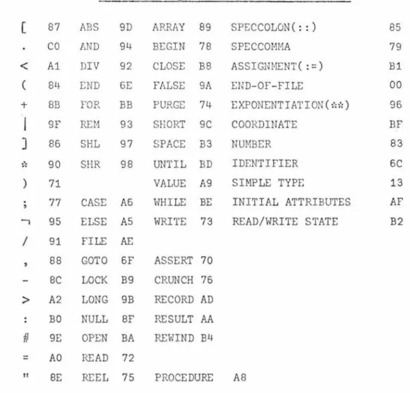
3.2 Pass One Output String Representing the Source Program
The source program minus blanks and comments, is passed to Pass Two in a coded form by way of a character array, BETWPASS. The codes correspond to the syntactic elements to be parsed in Pass Two, for example in Figure 3 if is represented by hexadecimal A3.
Figure 3
Pass One Output Codes (in hexadecimal)
( 87
co
<
A1( 84
+ BB
j
9F] 86
~·. 90 ) 71 77
1 95 / 91
88
ABS 9D
AND 94
DIV 92
END 6E
FOR BB
REM 93
SHL 97
SHR 98
CASE A6
ELSE AS FILE AE
GOTO 6F
ARRAY 89
BEGIN 78
CLOSE B8
FALSE 9A
PURGE 74
SHORT 9C
SPACE B3
UNTIL BD
VALUE A9
WHILE BE
WRITE 73
ASSERT 70 SC LOCK B9 CRUNCH 76
>
A2 LONG 9B RECORD ADBO NULL SF RESULT AA
#
9E OPEN BA REWIND B4=
SPEC COLON ( : : ) SPECCOMMA
ASSIGNMENT( : =) END-OF-FILE
EXPONENTIATION ( ~·.1.)
COORDINATE
NUMBER
IDENTIFIER
SIMPLE TYPE
INITIAL ATTRIBUTES
READ/WRITE STATE
"
AOSE
READ 72
REEL 75 PROCEDURE AS
DO 6D IF A3 IS 8A OF A7 OR 8D
SEEK STEP THEN TRUE
BS
BC
A4
99
REFERENCE 82
There are some special cases where a modification of the source program is required and these are the following:
1. The rese1~ved words and word pairs, integer, real, long real, complex, long complex, logical, bits, and string, receive the code for SIMPLE TYPE. 2. In a reference declaration, the left parenthesis
preceding the record class list specification part is omitted.
3. In a string declaration, if the length is explicitly specified, the entire length specification part is omitted.
4. A comma appearing in the identifier list of a
declaration or in the record class specification part of a reference declaration, receives the code for
SPECCOMMA.
5. Each identifier is replaced by a 3 byte code. The first byte is a code for IDENTIFIER. The following two bytes contain the unique identifier number
(starting from 0). In Figure 2, the identifier A has an identifier number of 1 corresponding to its
index in IDLIST.
6. Each number is represented by a 1 byte code for NUMBER, followed by a 1 byte indication of the type of the number, followed by the number (not split across word boundaries).
8, Each string sequence is represented by a 1 byte code for " followed by a 1 byte indication of the
length of the sequence minus 1, followed by tho
string sequence.
9. In a file declaration, if there are any attribut·es
ex~licitly declared, a code for INITIAL ATTRIBUTES
is inserted after the left parenthesis and before
any attributes.
10. In a read/write statement a code for READ/WRITE
STATE is inserted after the reserved words read
or write.
11. Each new coordinate is indicated in the output
string by a 3 byte code. The first byte specifies COORDINATE and the following 2 bytes give the
coordinate number.
12. The reserved word comment and all characters up
to and including the next semicolon are omitted.
13. An identifier following the reserved word end
is omitted.
3.3 Pass One Table Output
As well as the coded string of the source program, there are
three tables that Pass One partially fills to output to Pass Two.
They are the NAMETABLE, BLOCKLIST, and RCCLIST.
The BLOCKLIST table has a word entry for each block in the source
program in the order of block opening. Each program has a pre
-defined outer-block numbered O, containing predefined identifiers,
for example SQRT. Each full-word entry is divided into thirds
(i.e. 16 bit parts) . The first 16 bi ts contain the ·number of identifiers declared in that block. The second 16 bits contains a pointer (i.e. index) to the entry in NAMETABLE which contains
the first identifier declared in the block. If no identifiers
are declared these first two parts will contain zero. The
surrounding block of the current Dlock. In figure 4, the first BLOCKLIST entry points to LONGSQRT and takes in both LONGSQRT and SQRT which are both predefined. The second BLOCKLIST
entry points to i, and takes in i, j and L Hh.ich are declared in
the outer block of the source program and the third entry points to the control variable i .
Figure 4
Example of BLOCKLIST and NA!,JETABLE
2
3
1
BLOCKLIST
0 0
3 0
~
2 1begin
integer i, j ;
j: =O;
for i:=1 until 7 do j:=j+l;
L
:
end.
NAMETABLE
>
entry for LONGSQRTentry for SQRT
~
entry for. ientry for i
entry for j
entry for L
Blocks are entered and closed by the following rules: 1. Each begin is the entrance to a block and the
2. Each statement in a for statement is surrounded by a block in which the control variable is implicitly declared.
3. Each procedure body is surrounded by a block in which any formal parameters are declared.
The NAMETABLE has all entries of identifiers declared in a block grouped together. Thus permanent entries are not made until the block has been closed. For example in Figure 4 the entry for
the control variable is before the group of entries of the identifiers declared in the scope of the outer block.
The full layout and field contents of NA~IBTABLE are given in Figure 5 (see next chapter). Pass One only puts in enough information so that Pass Two can check for any semantic errors (for example type compatibility in expressions) in the source program. The information entered by Pass One consists of the follm-ling attributes appropriate to the variable
IDNO The number assigned to the
SIMPLETYPE
TYPE
TYPEINFO
identifier. This number is equal to the number of
the IDLIST entry. Virtual parameters have idno 0.
If a procedure (not formal
VR
or virtual) then the block
number of the formal parameters. If formal or virtual parameter
RCCLNUM
1 if value 2 if result
SIMTYPEINFO If string then length-1. If reference then pointer to RCCLIST
All predefined identifiers, for example SQRT, are entered
permanently into NAMETABLE with all fields filled, upon entering Pass One.
Each entry of RCCLIST is 1/3 word (i.e. 16 bits) and contains the IDNO of a record class (or classes) to which the reference is bound. A zero entry shows the end of a group. The
NAMETABLE entry for a reference contains a pointer (i.e. index) to the first entry of RCCLIST for that reference. For example,
reference (node1, node2)p
would cause the entry in NAMETABLE for p to have a pointer in SIMTYPEINFO to RCCLIST as follows:
J
pointer for p in from entry NAMET ABLE RCCL~~~::::: .~IL-_2_._6_.__o_._j_-_______ _Chapter 4
PASS TWO
Pass Two performs the following tasks:
1. A complete syntax analysis of the source program as
passed to it from Pass One.
2. A thorough error analysis.
3. Completes the NAMETABLE entries.
4. Builds constant tables.
5, Converts the program to an intermediate language
to be passed to Pass Three for the generation of code.
The syntax analysis is mainly done by means of a simple precedence
analyzer, but in the case of file declarations and read/write
statements the analysis is done by recursive descent.
The interpretation rules which are associated with the syntax
rules of the grammar specify the other actions of Pass Two.
4.1 The Parsing Algorithm
The parsing algorithm used in the compiler is a bottom up siwple precedence method. The ALGOL W grammar was rewritten in a
simple precedence form (see Appendix A) and a separate program
was developed to check the precedence relations ( [1lt] and (15])
of the rewritten grammar and that it was, in fact, simple
precedence. This program for checking for simple precedence
had a large process~time but after some manipulation a precedence
matrix was produced.
entry to Pass Two.
This matrix is already initialized on
The algorithm for using this matrix for the syntactic analysis
is, with a couple of modifications, that used by Wirth in
Euler (16]. When looking up to see if a string is the right
are checked before the matching is checked. This makes it easier to search through the production array. Also, the full precedence matrix is used as opposed to using precedence functions so that errors are detected sooner and thus providing for better error recovery. The third change is that the relations found when scanning to the right looking for ·> are stacked. This makes them easily retrieved when scanning to the left for<·
rather than having to be refetched from the precedence matrix.
The precedence matrix is packed four elements to a byte in order to save space, so a fetch from the matrix is slower than a
retrieval from a stack. However, every time a reduction is made , the relation of the new symbol to the symbol below it on the parsing stack has to be fetched from the precedence matrix and stacked. This gives a gain in efficiency with right parts of length greater than two, but no significant gain with right parts of length one or two.
Every syntax rule has a corresponding interpretation rule which is executed when the reduction is made. This interpretation
rule checks semantics, for example type compatibility in expressions.
Associated with the parsing stack is a parallel value stack
(see 4.4) which contains information used by the interpretation rules.
4.2 Error Recovery
There are two ways in which syntactic errors are detected when using simple precedence analysis:
1. A reducible string (i.e. one delimited by<· and ·>)
is not the right part of any production.
2. The top of the parsing stack has no relation(<·,~,·>)
to the incoming symbol.
To recover from the first case, the statement in which the error
<caseseq>, or <endfile>, and the input string is advanced to end "·" begin or <endfile> If end is deleted from the
__
,
' ,
___
,.
parsing stack, it becomes the next incoming symbol, else the
next symbol in the input string is taken. Special care is taken to keep the block numbers the same as those assigned in
Pass One, so if a nonterminal which affects the value of the block number is removed from the parsing stack, the block number is correspondingly adjusted.
In the second error case, a number of recovery actions are possible:
1. A symbol can be inserted.
2. The top of the parsing stack can be deleted. 3. Another symbol can replace the top of the parsing
stack.
4. The incoming symbol can simply be stacked on the parsing stack (this is done if the other three can
not be done) .
If a symbol is to be inserted, it must have a relation to the
incoming symbol, and the top of the parsing stack must have a
relation to it. If the inserted symbol is ·> the incoming symbol, the input string is backed up and the inserted symbol
becomes the incoming symbol, otherwise the inserted symbol is
stacked on the parsing stack.
If a symbol is to replace the top of the parsing stack it must have a relation to the incoming symbol, and the next-to-top of the parsing stack must have a relation to it. If the replacing symbol is
·>
the incoming symbol, then the top of the parsingstack is deleted, the input string is backed up and the replacing symbol becomes the incoming symbol, otherwise the replacing
symbol just replaces the top of the parsing stack.
<·
or - the incoming symbol.An inserted or replacing symbol can be the cause of other error
messages especially in type compatibility, for example an undefined identifier is always assumed to be of type integer.
Special care has to be taken so that the same action is not
attempted the next time through. For example, if the top of
the parsing stack is <block body> and it has no relation to the
incoming symbol, a ";" may be inserted. "<block body>;" reduces to <block body>, so if the error routine is called again before the input string has advanced, another ";" must not be inserted. This is achieved by the use of a flag which indicates the last symbol inserted.
4.3 Storage Allocation
Program segment numbers are assigned by Pass Two. Each program,
block with declarations, or procedure with a body that is a block with declarations, is a separate program segment and is assigned a unique segment number. SEGNO contains the current segment number. SEGINDX contains the largest segment number
currently assigned. SEGLIST is an array with entries indexed by SEGNO and SEGINDX and holds the immediate surrounding segment
number.
All addresses of variables, array descriptors, files, and other
data are also assigned by Pass Two and are indicated in NAMETABLE.
An address consists of the hierarchy number (i.e. the lexical
level) plus the address relative to the beginning of the data
segment (the displacement).
Fields of records are given addresses relative to the origin of
the record. The length in words of any record in a record class
The dimension of an array is inserted in NA~IBTABLE when the array declaration is encountered. This information is used to compute the descriptor and to check the number of dimensions
each time that array designator occurs.
Addresses are allocated in the program segment of a procedure for descriptors of its formal parameters. Descripto1~s of actual name parameters are assigned addresses relative to the beginning of the data segment of the procedure. Addresses are allocated in the data segment for values of the actual value and result parameters, since they are treated as local variables while control is within the procedure body.
4.4 Value Stack
The value or interpretation stack consists of 4 row by 2 byte elements, and works in parallel with the parsing stack.
V1 Row 0
V2
Row 1 V21 V22
V34
Row 2
V3 V4
vs
Row 3I
~ 1 6 bits----,I
V1 Simple type information (see SIMTYPEINFO field in NAMETABLE, Figure 5).
V21 Type
V22 Simple type
V34 O (used in certain special cases detailed in 4.5) VS Output pointer
When an identifier is looked up in NAMETABLE, a pointer (i.e. index) to its entry in NAMETABLE is put in V1 and V2 is filled. When any node is put in the output array TREE (see 4.7), the tree pointer (i.e. index to the TREE array for that node) is put in
vs
.
4.5 Interpretation Rules
For every syntax rule of the grammar there is a corresponding interpretation rule which performs the semantic actions for that syntactic construction. These interpretation rules are contained in a procedure INTERPRET and are accessed via a case statement
which is indexed by the production rule number. The interprc:tation rules use the value stack (see 4.4) for working storage.
The semantic actions and value stack layouts for the major syntactic constructions are:
1. Simple variable declaration
a. Value stack layout is standard.
b. Each identifier is found in NAMETABLE, checked for multiple declaration and allocated an address. No output is generated.
2. Array declaration a. Value stack layout
V1 Pointer to NAMETABLE entry of first identifier.
V2 0
V3 Number of identifiers V4 Dimension
b. Identifiers in the list are counted, the simple types of the bound pair expressions are checked, the bound pairs are counted, addresses for descriptors are allocated, the array dimension is inserted in NAl1ETABLE for all the identifiers , and output is generated.
3. Procedure declaration
a.1 Value stack layout for procedure head
Vl Simple type information (if typed procedure) V21 Type
V22 Simple type (if typed procedure)
V3 and V4 Used when scanning virtual parameters VS Output pointer
a.2 Value stack layout for procedure body
Vl Simple type information of expression (if typed procedure)
V2 0 V34 0
VS Output pointer
b. Addresses are allocated for the descriptors of the formal parameters, the simple types (for a typed procedure) are compared, output is generated. 4. Record class declaration.
a. Value Stack layout
Vl Pointer to NAMETABLE for current field V2 0
V34 0
VS Pointer to NAMETABLE entry of record class identifier
b. The identifiers are located in NAMETABLE and checked for multiple declaration, an address is allocated for the record class descriptor, relative addresses are assigned to the fields and the
5. File declaration
a.
b.
Value stack layout
V1 Pointer to NAMETABLE entry of first identifier
V2 0
V3 Number of identifiers
V4 0
vs
Output pointerThe identifieps are located in NAMETABLE and checked
for multiple declaration, addresses are allocated,
attributes checked, and output generated.
6. Substring designator
a. Value stack layout is standard
b. The simple types of the simple variable, the index
expression and the length are checked, the length
is checked against the length of the simple variable,
and output is generated.
7. Array designator
a. Value stack layout
V1 Simple type information
V21 Type
V22 Simple type
V3 Number of dimensions
V4 Number of dummy subscripts
VS Output pointer
b. The number of dimensions and simple type of subscripts
are checked, output is generated.
8. Field designator
a. Value stack layout is standard
b. Simple type of the expression is checked, output is
generated.
9. Procedure designator
a. Value stack layout
V1 Simple type information (if typed procedure)
V22 Simple type (if typed procedure)
V31+ Pointer to NAMETABLE entry for current parameter VS Output pointer
10. If expression
a. Value stack layout is standard
b. Simple types of then expression and else expression
are checked for type compatibility, simple type
of expression in if clause is checked, output is
generated.
11. Case expression
a. Value stack layout
V1 Simple type information
V21 Number of cases V22 Simple type
V34 0
vs
Output pointerb. The simple type of the expression in the case clause is checked, cases are counted, simple types are
checked fo:r. compatibility, and output is generated.
12. argument1 {=,
>=,
<,
<=,>, and, or, +, - ~:, / , shr, shl, div, rem, :'::':, is} argumen t2a. Value stack layout is standard
b. Simple types of arguments are checked for type
compatibility, output is generated. 13. {-, -, , long, short , abs} argument
a. Value stack layout is standard
b. S~mple type of argument is checked for type compatibility, output is generated.
14. Record designator
a. Value stack layout (replaced by standard layout after structure is parsed)
V1 Pointer to NAMETABLE entry for current field V21 Number of fields
V22 Record class number
V3 0
b. The number of fields is checked, the simple type of each field is checked for compatibility, output is generated.
15. Blackbody
a. Value stack layout V1 0
V2 0 if no declarations, ffiF if enclosing block of procedure body (with declarations), #FF otherwise
V34 0
VS Output pointe1'
b. At begin the block number and hierarchy number are stepped, V2 and displaceme~t are set. At end the displacement and hierarchy number are restored. Output is generated.
16. Label definition
a. Value stack layout is standard
b. The segment nurrber and hierarchy number are inserted in NAMETABLE, output is generated.
17. Assignment statement
a. Value stack layout is standard
b. Simple types are checked for type compatibility, output is generated.
18. Case statement
a. Value stack layout is the same as for case expression b. Cases are counted, output is generated.
19. For statement
a. Value stack layout is standard
b. Simple types of expressions are checked, an address is allocated for• the control identifier, output is generated.
20. While statement
a. Value stack layout is standard
21. Assert statement
a. Value stack layout is standard
b. The simple type of the expression is checked, output
is generated.
4,6 Pass Two Tables
Pass Two completes the NAMETABLE and creates a literal table. The information entered in NAMETABLE is that in Figure 5 that was not entered in Pass One. Note that the TYPE entry for a formal or virtual parameter is changed from its contents at the end of Pass One.
Figure 5
Format of NAMETABLE and Field Contents After Pass Two
idloc1 idloc2 simtypeinfo
hierarchy prog.seg.
typeinfo
dimen type simpletype idno
vr reel. number
<---16 bi ts
---~I~
16 bi ts --->"'l~--16 bitsRow 0
Field
IDLOC1
HIERARGiY PROGSEG IDLOC2
Kind of Entry simple variable label
array
file
record class identifier record field
control identifier standard function formal parameter procedure
procedure
simple variable array
file
label
Contents
hierarchy number program segment hierarchy number hierarchy number hierarchy number hierarchy number
number
hierarchy number
simtypeinfo of argument hierarchy number
hierarchy number
program segment number relative address
relative address of descriptor relative address
relative address in label t able record class identifier relative address
record field
control identifier procedure
address relative to start of record relative addx,ess
relative addr·ess formal parameter
SIMTYPEINFO string
relative address length-1
TYPEINFO
VR
reference pointer to RCCLIST record class identifier record length label
procedure (not formal or virtual)
hierarchy number
block number of formal parameters
standard function simpletype of parameter record class identifier number of fields
formal procedure virtual procedure standard procedure formal parameter
virtual parameter
number of virtual parameters number of virtual parameters vr for parameters
1 if value, 2 if result, 3 if value-result
DIMEN
RCCLNUM
TYPE
SIMPLETYPE
IDNO
array
formal procedure virtual procedure
dimension
1 if has virtual parameters 1 if has virtual parameters record class identifier record class number
record field identifier record class number standard function
simple variable label
array procedure
record class
record field
control identifier standard function file
standard procedure
formal parameter virtual parameter integer
real
long real complex long complex logical string bits reference
1 if inline
0 1 2 3 4 5 6 7 8 9
16 + TYPE
32 + TYPE
1 2 3 4 5 6 7 8 9
the unique identifier number
Two tables for literals are constructed by Pass Two. The literal table (LITTABLE) contains all literals (numbers, character
strings, and bit sequences). The literal pointer table (LITPOINT -TABLE) contains the simple type, the length (if a character
The tables PRODUCTIONS, PRODINDX, and MATRIX are used by the syntactic analyzer and are initialized upon entry to Pass Two.
MATRIX contains the simple precedence relations of the Extended ALGOL W (simple precedence) grammar (see Appendix A) . The entries are packed four/byte.
PRODUCTIONS .contain the productions of the simple precedence grammar grouped so that all productions having the same leftmost symbol of the right part are together. The format for a production is the following:
production L : := R(l) R(2) ... R(N) O
<
N < 6 representation in PRODUCTIONS (12 bits/entry)N-1 R(l) R(2)
R(N)
L
production number
The symbol #FFF indicates the end of a production group.
PRODINDX is an index to PRODUCTIONS. The entry for a given symbol indicates the beginning of the group of productions of which that symbol is the leftmost symbol of the right part.
4.7 Pass Two Output
I-E--14
b i t s ~ l ~ s bits--::>!FJ,.ag
-
-
Opcode Conv Row 0Pointer Row 1
- - - 24 bi ts
FLAG is on (i.e. 1) if the right subtree is to be compiled first
and off (i.e. 0) if the left subtree is compiled first. Conversion of arithmetic type is indicated in the source program implicitly, by mixed-type expressions, or explicitly, by long or short.
In either case, the simple type to which the expression is to be converted is given in CONV. For a terminal node POINTER points to NAMETABLE or the literal pointer table (LITPOINTTABLE). For a nonterminal node POINTER points to the last node of the first subtree. The first node in TREE only uses the POINTER field which points to the end of TREE.
Example from [2].
program fragment:F(B,5,C+D,GOTO X) -Fis a procedure
C is integer
tree:
Dis real
AP)
/ \
AP, GOTO
/ ~
\
AP, . + X
/ \
/
'
\
AP, 5 C D
/ \
F B
TREE:
FLAG OPCODE CONV POINTER
FUNCID points to NAMETABLE entry for F
1-E--VARID points to NAMETABLE entry for B
0 AP,
NUMBER points to literal table entry for 5
f,E---0 AP,
VARID 2 points to NAMETABLE entry for C ~
VARID points to NAMETABLE entry for D
0 +
0 AP,
l<E--LABELID points to NAMETABLE entry for X
GOTO
Figure 6
Pass Two Output Vocabulary
Operator Code Remarks
A:Binary Operators
+ 1
I
L:=
A:=
S:=
R:= STEPUNTIL DIV REM
<
<=>
>= = -, :: L:=2 A:=2 S:=2 R:=2 2 3 4 5 6 7 8 9 10 11 12 13 ill 15 16 17 18 19 20 21 22 exponentiation logical assignmentarithmetic assignment
string assignment - conversion field contains string length reference assignment
conversion bits indicate length for string comparisons
multiple assignment
(Conversion field may contain string length for string arguments) AP) 26 Indicates end of actual parameter
list. Conversion bits indicate
conversion of result of function call.
INDX 27 Indicates subscripting operation.
Conversion bits can occur only with
last such operator and indicate that
REFX IFEXP PCL SUBSTRING SHL SHR BB END AP, R, AR, AR) R) LOGOR BITOR LOGAND BITAND ITERST ITERST2 FORLIST FORCL 28 29 30 31 32 33 34 35 36 37 38 39 40 41 42 43 44 45 46 47 48 49
ENDFORLIST 50
Indicates computation of field
(first argument) of record reference (second argument)
Indicates that label should be issued for end of if expression and unconditional jump patched.
Conversion hits indicate that
resulting expression must be converted. Indicates end of procedure declaration
left shift right shift
Indicates end of declarations, beginning of blackbody
for actual parameters for record designators for array declarations
indicates end of array declaration indicates end of record designator OR of logicul arguments
OR of bit sequences AND of logical arguments AND of bit sequences
indicates generation of transfer to iteration test for simple for statement
indicates generation of transfer to iteration test for for statement with for list
UJIFEXP UJ CL IFST IS WHILEOP WHILEST
IFJ
SPACE SEEK CLOSE LOCK INIT) INIT, LIST, EDITSPECS FORMLIST FILEPT RWHEAD CARCONT
B:Unary Operators 51 52 53 54 55 56 57 58 59 60 61 62 63 64 65 66 67 68 69 70 71 72
UMINUS 73
ABS 74
indicates unconditional jump in if expression
indicates issue jump to end of case list or if statement to be patched
indicates label should be issued for end of case statement and jump
addresses patched
indicates label should be issued for end of if statement and addresses patched
array bounds colon
indicates NOOP (statement separator)
indicates issue jump on condition false to end of if expression or if statement
indicates end of initial attributes for file declarations
I/O list separator
LOG, BIT, GOTO STACKADDR ASSERT READ WRITE CLOSEST LOCKST OPEN REWINDST LISTPART COORD CASE SEG
C:Terminal Nodes BEGIN NUMBER VARID LABELID ARRAYID FUNCID RCCLID FIELDID CONID PROCDC 77 78 79 80 81 82 83 84 87 88 89 90 91 93 94 95 97 98 99 100 101 102 103 104 105 106
negation of logical value negation of bit sequence
label colon
For implicit subroutine. If block expression conversion bits indicate if value of block is to be converted
Pointer is the coordinate number. Unary operator for BEGIN, PROCDC, ARRA YDC , 11
, " , FI LE DC nodes
Conv field is the simple type if
expression.
of cases.
Pointer is the number
Indicates program segment. contains segment nunilier
Conv contains block number if begins data segment
Pointer>
Pointer points to literal pointer table
FILE ID ATTRIB ATTRIBMNEMON BIT STRING TRUE FALSE IF WHILE NULL NULLST ARRAYDC
FILEDC
PURGE REEL CRUNCH SPACEV LINE SKIP NO STFUNCID STPROCID 107 108 109 111 112 113 114 115 116 117 118 119 120 121 122 123 124 125 126 127 128 129 130
Pointer points to literal pointer table
Pointer points to literal pointer
table
indicates undefined reference
indicates empty statement
Array declaration.
to first identifier.
number of identifiers
Pointer points
Convis the
indicates dummy array subscript
File declaration.
first identifier.
of identifiers
Pointer points to
Convis the number
Chapter 5
PASS THREE
The essence of Pass Three is the algorithm for scanning the linearized tree, beginning at the root node. The flag with each binary node indicates which branch the scan should follow. The operator nodes are not otherwise examined at this stage.
Pointers to the nodes are stacked in STACK as they are encountered in the scan for easy retrieval. Code generation begins with the first terminal node encountered and the tree is traversed by the generating routines.
The code produced is Burroughs B6700 machine code [17) and is put into standard B6700 code files [18). Before a discussion on the code produced can be meaningful, some understanding of the operating system and the stack (not to be confused with the array STACK) operation is required. The first part of this chapter gives a brief insight to these features , and if a more detailed description is required the reader is referred to [17] and (19).
5.1 B6700 Architecture
The B6700 follows the design of the simulated machine of Randell and Russell [20], and has a typed memory (i.e. there are a few bits of each word which are used as a tag indicating what type of
information the word holds) consisting of 51 bit words. The bits 50, 49, 48 are the tag bits, bit 48 is a memory protection bit which if on indicates the word can not be written into by the normal store operators, and the remaining 48 bits (47 to 0)
Figure 7
B6700 Word Formats With Tag Mnemonics
DATA WORDS
!oooj EXPONENT
!010
I
EXPONENTjo10
I
EXPONENTI
I
I
I
I
MANTISSA
MANTISSA
MANTISSA
Single-precision operand
Double-precision operand
- 1st word
~6 bits~~39 bits-~ I
Double-precision operand
- 2nd word
DESCRIPTOR WORDS
I
LENGTHI
ADDRESS Data Descriptor (DD)I
LENGTHl
ADDRESS Segment Descriptor (SD)l~2obits~20 bits~
SPECIAL CONTROL WORDS
011 STACK DISPLACEMENT
NO.
I
111 ISTACK OPERATOR
NO. INDEX
I
_ OPERATOR INDEXLL
I
I
LL
I
I
l
I
DFI
ADDRESS COUPLEADDRESS
I
COUPLEMark Stack Control Word (MSCW)
Program Control Word (PCW)
I
oo,
I I
1
~g~~~:1
I
I I
I
-
~
[
_
o
_
o,
I I
s~~~K
DISPLACEMENiJ:LTA
I~10bits~E--16 b i t s ~ ~14 bits~
The memory is of the segmented virtual type.
Indirect Reference
Word (IRW)
Stuffed Indirect
Reference Word ( IRWS)
The user may use a
number of linear memory segments of varying lengths so there may
be more main memory required than is available. Although the
user assumes all his segments are in high speed memory, it is
likely some are being held on secondary storage such as a disk.
The Master Control Program (MCP) brings the required segment into
the main memory when it is needed. So that it can do this, each
segment is described by at least one tag 5 word (descriptor) and
any reference to a segment must be made through a descriptor. As
seen in Figure 7, descriptors contain the main memory or disk
address of the segment dE:scribed plus a presence bit which if on
indicates the segment is in main memory. If a segment is referred
to that is not in main memory, the MCP fetches it and changes
the descriptor to show that the segment is then in main memory.
If the MCP removes a segment from main memory it turns off the
presence bit in all descriptors of that segment, and replaces the
memory address by a disk address. Program segments are read-only
so they are not removed to disk, just removed from main memory.
A program segment has only one descriptor. A program (Burroughs
literature calls these processes) may have more than 1 segment
and all their descriptors are kept in a stack pointed to by the
level 1 display register. The stack proper for a process starts
Data segments are more complicated because as they are arrays there can be many references to them held in the stack. When a data segment is removed from main memory all stacks in the
system are searched for references into the data segment and all presence bits are turned off. One descriptor is chosen as the master descriptor and holds the disk address of the data segment and all the other descriptors are copies and contain the
stack address of the master. If a descriptor is a copy the copy bit (C in Figure 7) is turned on. When a reference is made to an absent data segment the MCP fetches it back from disk and all other references use the copies to obtain the main memory address from the master descriptor.
Two other methods for addressing data or program code is provided. They are the Indirect Reference Word (IRW) and the Stuffed
IndiPect Reference Word ( IRWS). These address data located
within the process's stack and their address fields both hold relative addresses. The IRW addresses information which is
global or local to the particular active procedure. The IRWS is used for addressing across stacks and for handling parameters where the actual parameters are not necessarily within the
addressing environment of the procedure to which they are passed
and can not be accessed by an IRW. The IRW has in its Address Couple field a Display Register number and a Displacement. The IRWS holds three bits of information: (a) a Stack Number,
(b) the start of the addressing space of the process within that
stack, and (c) the displacement of the information within that addressing space. An IRW can be changed to an IRWS by the use of the operator stuff environment-STFF .
•
5.2 Program Structure in Memory
A program in memory occupies separately allocated areas, i.e. each part of the program can be anywhere in memory with the
The separately allocated areas of a program are (see Figure 8):
1. Program Segments. These hold a sequence of instructions (syllables) which the processor
executes. The program segments hold no data and are never modified.
2.
3.
Segment Dictionary. This is a table containing the descriptors of the program segments.
Figure 8
Object Program in Memory
Object Object
D[4]~ program program
stack code
containing segment
D(3] variables (n+1)
and ' 7
dynamic status
D[2]-) Object
program
code
Object
l
segmentI
program I I (n)
I
segment ! ~
.,.
dictionary
S.D. prog. , _
S.D. prog.
Seg.Des.O.B. I - Object
D[1]--? program
code
MCP stack outer
and block
segment code
dictionary segment
5.3 Stack Operation
The stack arrangement (see Figure 9) has two top-of-stack registers (A and B) with associated validity bits. With each top-of-stack register there is a companion register (X and Y) which is used to hold the second half of a double-precision operand. When held in the memory stack a double-precision operand is held in two adjacent stack words. For simplicity
in this discussion it is assumed all operands are single-precision. The necessary changes for double-precision operands will be
fairly obvious , for example when an operand is moved from the stack into the top-of-stack register tl1e tag bits are checked and if a double-precision operand then two stack: words are moved into A and X which are then concatenated. The stack top is pointed to by the S register and the address-chain is given by the F register. The ma.chine also has a check to see that the stack bounds are not violated.
A
B
s
I
I
:r
7
Figure 9 Stack ArranF,;ement
y
X _f _ ~ _
!
I~
--
-
--
- - -
----
~
r--
-
---.,
I I
I I I I i
I
I
4
I I I I(top) (address-chain
(z::!_
II I I
~ I
I
I I
I
I
<f- (display)
F
D(4]
The stack operates as a last in, first out storage area. An operand is stored into register A with consequent push-downs into register Band into the memory location pointed at by register S. Extraction of data is from register A with consequent pop-ups from Band the location pointed at by S.
The contents of Sare incremented by 1 on a push-down and decremented on a pop-up. These actions are performed
automatically by the processor to the requirements of the operator currently being executed.
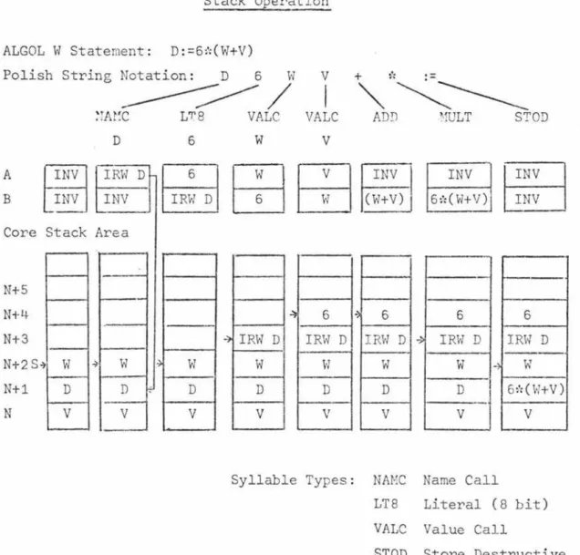
5.4 Example of Simple Stack Opel'ation
In the program segments the instructions are kept in the order of executing the source program in reverse Polish order. In this section, a simple example of the stack operation when
executing the statement D:=6*(W+V) will be discussed but the
Figure 10
Stack Operation
ALGOL W Statement: D:=6*(W+V)
Polish String Notation: D 6 W V
+"":':~~
A
B
Core Stack
N+S
N+4
N+3
N+2 S~
N+1
N
-w
D
V
_______----;-
~
/
I
~TAt~C L'T.'8 VALC VALC ADD ~ULT STOD
D 6
IRW D
I
IR:
DI
INVArea
~
w
~w
D D
V V
w
V0~~
~~~
INV
6:':(W+V)
~ 6 I"> 6 6 6
~ IRW D IRW D IRW D ~ IRW D IRW D
----w
w
w
w
~w
D D D D 6~:(W+V)
V V V V V
Syllable Types: NAMC Name Call
LT8 Literal (8 bit)
VALC Value Call
STOD Store Destructive
When D: =6:':(WtV) is changed to Polish notation the result is
( LTB) . Since Wand V are to be added, the variables are put
in the stack by Value Call syllables. The ADD operator adds
the two top operands and places the sum in the top of the
stack (in this case register B). The multiply operator (MULT)
then multiplies the two top stack operands and places the result
in the top of the stack. The store syllable (STOD) examines
the two top of stack operands looking for an IRW or Data
Descriptor. In this example it finds an IRW which addresses
the location where the computed result is to be stored and
stores it.
5.5 Syllable Format and Types
A machine language program is a string of syllables which are
usually executed sequentially. Each word in the memory contains
six 8-bit syllables with the first labelled syllable O and
is contained by bits 47 to 40 inclusive.
There are three types of syllables (see Figure 11) :
(a) Name Call , (b) Value Call, and (c) operators. The
two high-order bits (bits 7 and 6) determine which type ct syllable is.
(Bits 7 and 6)
Identification
00
01
1X
Figure 11
Syllable Table
Syllable No. of
Type syllables
Value Call 2
Name Call 2
Operators 1 to 7
Function
Brings an operand
into the stack
Brings an IRW into
the stack
Performs the