1
UNIVERSITI TEKNIKAL MALAYSIA MELAKA
APPLICATION OF
PROGRAMMABLE LOGIC CONTROLLER
(PLC)
ON THE LOW VOLTAGE DISTRIBUTION
AUTOMATION SYSTEM (DAS)
This report is submitted in accordance with the requirement of the Universiti Teknikal Malaysia Melaka (UTeM) for the Bachelor of Electrical Engineering Technology (Industrial
Power) with Honours.
by:
SITI SAKINAH BINTI MOHAMMED KHIR B071410776
920812-07-5342
2
DEDICATION
Dedicated to my beloved parents, MOHAMMED KHIR BIN OSMAN
4
DECLARATION
I hereby, declared this report entitle “APPLICATION OF PROGRAMMABLE LOGIC CONTROLLER (PLC) ON THE LOW VOLTAGE DISTRIBUTION
AUTOMATION SYSTEM (DAS) " is the result of my own research except as cited in the references.
Signature : ... Name : SITI SAKINAH BT MOHAMMED KHIR
5
APPROVAL
This report is submitted to the Faculty of Engineering Technology of UTeM as a partial fulfillment of the requirements for the degree of Bachelor of Electrical Engineering Technology (Industrial Power) with Honours. The member of the supervisory is as follows:
6 ACKNOWLEDGEMENT
First and above all, I would like to thank my beloved parent for prayers and blessings that kept me motivated throughout this journey. I tried my best and gave a full commitment to finish this project at the right time as required. I would like to express my deepest thanks to, Assoc. Prof. Mohd Ariff Bin Mat Hanafiah, my supervisor for the Final Year Degree Project at Faculty of Engineering Technology, for giving me many advices, ideas, guidance and motivations to complete this assignment. His flexibility gave me the opportunity to complete this task without any pressures and headache.
7 ABSTRACT
8 ABSTRAK
9 TABLE OF CONTENTS
CHAPTER TITLE PAGES
ACKNOWLEDGEMENT i
ABSTRACT ii
ABSTRAK iii
TABLE OF CONTENTS iv
LIST OF FIGURES vii
LIST OF TABLES ix
LIST OF SYMBOLS x
LIST OF ABBREVIATIONS xi
1 INTRODUCTION 1
1.1 Project Background 1
1.2 Problem Statement 2
1.3 Objectives 3
1.4 Project Scope 3
1.5 Contribution of Project 4
2 LITERATURE REVIEW 5
2.1 Overview 5
2.2 Distribution Automation System (DAS) 5 2.2.1 Benefits of Distribution Automation System (DAS) 6 2.3 Fault Location, Isolation, and Service Restoration (FLISR) 7 2.4 Human Machine Interface (HMI) 8 2.5 Programmable Logic Controller (PLC) 10
10
2.6 Communication Networks 13
CHAPTER TITLE PAGES
2.7 Low Voltage Distribution Substation Panel 14 2.8 Industrial or Business Review 16 2.9 Related Previous Works 18
2.9.1 Customized Fault Management System for Low Voltage (LV) Distribution Automation System
18
2.9.2 The Implementation of Fault Management in Distribution System Using Distribution Automation System (DAS) in Conjunction with SCADA
19
2.9.3 Development of Customized Distribution Automation System (DAS) for Secure Fault Isolation in Low Voltage Distribution System
19
2.9.4 A Low Cost Wireless Data Acquisition System for Distribution Automation System
20
2.9.5 Distribution Automation Case Study: Rapid Fault Detection, Isolation, and Power Restoration for Underground Distribution System
20
2.9.6 Communication System for Distribution Automation Using CDMA
21
3 METHODOLOGY 22
3.1 Overview of Project Flow 22 3.2 Progress of the Project 24
3.3 Software 27
3.4 Hardware 28
11
CHAPTER TITLE PAGES
3.4.5 Interfacing Device 32 3.5 Communication Network 33 3.6 Low Voltage Substation Prototype Panel Operation and
Testing
34
3.6.1 Overall Operation 34 3.6.2 Local Operation 35 3.6.3 Remote Operation 35 3.6.4 Cut Off and Restoration Process 36 3.6.5 Fault Detection from MK2200 Protection Relay 37
4 RESULT AND DISCUSSION 40
4.1 Overview 40
4.2 Human Machine Interface (HMI) 40
4.2.1 Main Screen 41
4.2.2 Grid Screen 42
4.2.3 Single Line Diagram Screen 43
4.2.4 Alarms Screen 45
4.2.5 Trend Screens 46
4.2.6 Events Screen 48
4.3 Town Model 49
4.4 Overall System Operation 52 4.4.1 Integrating with PLC KIT
5 CONCLUSION AND RECOMMENDATION 55
5.1 Conclusion 55
5.2 Recommendation 56
12 LIST OF FIGURES
Figure Title Page
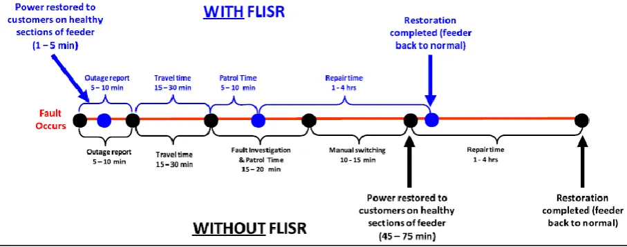
2.1 Architecture for Distribution Automation System 6 2.2 Difference between conventional restoration and FLISR
implementation
7 2.3 Illustration of a simple FLISR operation 8 2.4 Programmable Logic Controller (PLC) 12 2.5 Over Current and Earth Fault Detection Relay (MK2200) 15 2.6 Universal Measuring Device (UMG96S) 15 2.7 Overview of the electric relay structure 16 2.8 Typical financial loss per outage 18 3.1 Overall project architecture 23 3.2 Flow chart of the project development 26 3.3 Flow chart for the Human Machine Interface (HMI) development 27 3.4 The low voltage substation prototype 28 3.5 The overall substation system single line diagram 29 3.6 Single-line diagram of the control circuit 30 3.7 Typical MK2200 connection diagram 31 3.8 Connection diagram of UMG96S with RS232, RS485, and digital
outputs
32 3.9 PROGRAMMABLE LOGIC CONTROLLER (PLC) blocks
configuration
33 3.10 Comparison between RS-232 and RS-485 34 3.11 The relays placement in the substation prototype 39 4.1 The main screen of the HMI 41 4.2 The grid screen when the system is under normal condition 42 4.3 The grid screen when the system is in blackout condition 43 4.4 Single line diagram during normal condition 44 4.5 Single line diagram during blackout condition 44
4.6 The online alarm 45
4.7 The alarm history 46
13
4.11 The events screen 49
4.12 The schematic circuit of the town model 50
4.13 The town model 51
14 LIST OF TABLES
Table Title Page
2.1 Types of HMI 9
15 LIST OF SYMBOLS
I/O - Input/Output kΩ - kiloOhms kV - kiloVolt mV - milliVolt
16 LIST OF ABBREVIATIONS
ABB - ASIA Brown Boveri
CDMA - Code Division Multiple Access DAS - Distribution Automation System DNP - Distributed Network Protocol ELCB - Earth Leakage Circuit Breaker
FLISR - Fault Location, Isolation and Service Restoration GSM - Global System for Mobile Communication GUI - Graphical User Interface
HMI - Human Machine Interface
IEC - International Electrotechnical Commission IED - Intelligent Electronic Device
IEEE - Institute of Electrical and Electronics Engineers IWS - Indusoft Web Studio
KEPCO - Korea Electric Power Corporation LAN - Local Area Network
LV - Low Voltage
MODEM - Modulator/Demodulator NC - Normally Close
NO - Normally Open
OLDC - Operation Logic Down-Counter OLUC - Operation Logic Up-Counter PIC - Peripheral Interface Controller PLC - Power Line Carrier
PLC - Programmable Logic Controller RS - Recommend Standard
RTU - Remote Terminal Unit
SCADA - Supervisory Control and Data Acquisition SOE - Sequence of Events
17
UDAS - Underground Distribution Automation System UTeM - University Technical Malaysia Melaka
VB - Visual Basic
WAP - Wireless Application Protocol WLAN - Wireless Local Area Network
18
CHAPTER 1
INTRODUCTION
1.1 Project Background
Electricity has become one of the major needs in everyday life, especially with increasing demand for energy nowadays. Electric power system is divided into several parts such as generation, transmission, distribution and load (customers). The power grids transmit electricity at different voltage levels for each part, which are Extra High Voltage (above 230 kV), High Voltage (35 kV to 230kV), Medium Voltage (1 kV to 35 kV), and Low Voltage (up to 1 kV) [1]. Automation of the electric parts or components on distribution level is called Distribution Automation System (DAS), and it is in the Low Voltage level. According to IEEE, "DAS is a system that enables an electric utility to monitor, coordinate, and operate distribution components in a real-time mode from remote locations [2]."
19
In this project, a distribution substation model is build for the DAS application. The distribution substation consists of the incoming, outgoing, and the load. The controller circuit of this substation is based on input and output of PLC. Moreover, a HMI will be constructed and interfaced with this substation so that its functions can be monitored and controlled from remote locations. Developments will be made so that the distribution substation will be able to perform the FLISR operation.
1.2 Problem Statement
When a fault occurs in distribution power lines, the supply will be interrupted and there will be outage of power. This outage results in disturbances for consumers, especially for industries which wanted to reach a production target. The outages often cost industries a huge amount of money. This affects the reliability and efficiency of the electric utility in providing electric supply. The main challenge for any power distribution utility is to locate or identify the faulty section, isolate them and restore the non faulty sections as quickly as possible. This is impossible to be achieved with manual procedure in which the utility staffs have to patrol in the area for hours to locate the faulty section.
20 1.3 Objectives
The objectives of this project are:
1) To build a low voltage substation prototype with controls circuits for automation implementation.
2) To construct a Human Machine Interface (HMI) using Indusoft software for SCADA purposes.
3) To integrate with PLC and build a town model which is capable to execute the Fault Location, Isolation, and Service Restoration (FLISR) function.
1.4 Project Scope
The main objective of this project is to build complete components of the Distribution Automation System (DAS). The substation model will be built by installing the necessary equipments or components in the substation. Some of the devices that are installed in the substation for the automation purposes are Programmable Logic Circuit (PLC), Intelligent Electronic Device (IED), and communication protocols. The PLC used is OMRON PLC Training Kit (OPLC-TK-V3)while the IEDs used are MK2200 and UMG96S.
MK2200 is an over current and earth fault detection relay, while UMG96S is a universal measuring device used to measure the electric parameters. The communication protocols that are used include RS485, RS232, and IEC61850.These protocols are responsible for communication between the devices. What is more, a Human Machine Interface (HMI) will be constructed using Indusoft software and will be interfaced with the hardware for future development. Indusoft is a powerful and efficient HMI SCADA software platform that provides supervisory control and data acquisition applications [4]. Thus, the operating personals can monitor and control the operation of the substation using the HMI from remote locations.
21
FLISR system will locate the fault, isolate the fault and restore the supply to unaffected areas. Some algorithm will be developed in future and uploaded in the system. The algorithm programs are responsible to make the system to take decisions during fault conditions.
1.5 Contribution of Project
This project is anticipated to contribute to the modernization of electric distribution networks in our country. There are numerous benefits from the implementation of this project. Some of the benefits are to the operational, maintenance, financial, and customers. This project will improve the reliability by mitigating outage duration using auto restoration process. It also provides better fault detection and diagnostic analysis. Besides, it also minimizes man hour and man power in managing the utility.
22
CHAPTER 2
LITERATURE REVIEW
2.1 Overview
In this chapter, it will describe the theoretical information and methods that have been used in order to accomplish the objectives. Numerous studies have been carried out which comprises the hardware and software parts. Moreover, information from previous works also has been analyzed in this chapter. Thus, this chapter provides comprehensible information about the system.
2.2 Distribution Automation System (DAS)
As stated by the IEEE, DAS is a system that enables an electric power provider to monitor, coordinate, and operate distribution components or devices in a real-time mode from remote locations [2]. Distribution automation system utilizes the modern communication technologies in carrying out its interaction between devices. The rapid development of communication technologies, such as wireless devices contributes to the feasibility of constructing automation systems.
23
[image:23.595.119.521.156.448.2]operator displays and workstations for executing, monitoring, and controlling the program [5].
Figure 2.1: Architecture for Distribution Automation System [5].
2.2.1 Benefits of Distribution Automation System (DAS)
The significant benefits of automation are as follows:
a) Enhanced electric service efficiency, quality, and reliability. b) Mitigate manpower intervention and operating costs.
c) Power outage duration is minimized by the implementation of auto restoration process.
24
e) Improvised fault detection and behavior analysis. f) Quick regeneration contributes to revenue elevation.
g) Interruption cost is mitigated, especially for important customers such as industrial and commercial customers.
2.3 Fault Location, Isolation, and Service Restoration (FLISR)
[image:24.595.109.563.447.626.2]FLISR implementation has the objective of locating a fault on a distribution line, isolating the fault, and restoring service to the healthy sections in an automated fashion without or with slight personnel intervention. FLISR implementation increases reliability and reduces outage duration. It also contributes to the efficient use of personnel and resources such as vehicles. In fact, reliability is naturally increased since shorter time is required for locating and isolating the faulted areas, as well as for restoring consumers located on unaffected areas. Figure 2.2 below depicts the comparison of time taken to solve faulted section by FLISR and conventional restoration. On the other hand, Figure 2.3 illustrates a simple FLISR operation.
![Figure 2.1: Architecture for Distribution Automation System [5].](https://thumb-us.123doks.com/thumbv2/123dok_us/134157.12951/23.595.119.521.156.448/figure-architecture-for-distribution-automation-system.webp)