Abstract—The Smart Grid will enable a new era of electricity generation, transmission, distribution and consumption driven by efficiency, reliability, flexibility and environmental concerns. A key component of the Smart Grid is a communications infrastructure for data acquisition, monitoring, control and protection. In this paper, we evaluate the key performance aspects of an LTE Release 8 FDD network as the wide area communications network for Smart Grid applications. We develop analytical results for latency and channel utilization and discuss the implications for Smart Grid traffic sources, particularly the fact that system capacity is likely to be control channel limited. We also develop an OPNET based discrete event simulation model for a PMU based fault monitoring system using LTE FDD as its communication medium and use it to validate the analytical findings. In particular, we demonstrate how uplink data plane latencies of less than 10ms can only be achieved using small application layer packets. These findings can be used to understand how to best deploy an LTE FDD network in a Smart Grid environment and also in the development of new radio resource management algorithms that are tailored specifically to Smart Grid traffic sources.
Index Terms—LTE, Smart Grid Communication, Latency, Channel Utilization, Fault Monitoring, M2M
1 INTRODUCTION
he current generation electricity grids were developed several decades ago to deliver bulk supplied energy to homes and other premises in a semi-efficient manner by regulated and vertically integrated utility companies. More recently, factors such as market deregulation, the introduction of distributed generation based upon unpredictable renewable energy sources and new load types such as plug-in electric vehicles have emerged. Based upon these new trends, the Smart Grid concept has been developed to enable a new era of electricity generation, transmission, distribution and consumption driven by efficiency, reliability, flexibility and environmental concerns [1][2][3]. Potential Smart Grid applications include Advanced Metering Infrastructure (AMI) [4][5], Demand Response (DR) [4] and Wide Area Measurement System (WAMS) [6][7] among others. Some of these applications, particularly AMI which involves transferring Smart Meter readings to a central server, and WAMS which involves transferring phasor measurements from Phasor Measurement Units (PMUs) located in the field to a central server, involve much more uplink than downlink data.
The Smart Grid architecture is seen as the integration of power, communications, signal processing and control engineering techniques. The communication network within the Smart Grid structure acts as an enabling technology which allows information exchange among different entities of a grid for data acquisition, monitoring, control and protection purposes [8][9]. The design rules of a Smart Grid communication network are different to a typical communication network designed for consumer and enterprise use because we are mainly dealing with machine-to-machine (M2M) communication in which there are a relatively large number of devices sending relatively small size packets [10]. A Smart Grid may include a suite of wireless communications systems ranging from low range sensor networks based upon IEEE 802.15.4 and ZigBee [11], through medium range Field Area Networks (FANs) based upon IEEE 802.11 and Wi-Fi to wide area networks based upon 3GPP Long Term Evolution (LTE) or WiMAX [12].
LTE [13] has attracted considerable interest for deployment as the wide area communications network in a Smart Grid environment for several reasons: low cost due to the economies of scale associated with a global standard, wide area wireless support across a power transmission and/or distribution network, efficient use of radio resources due to packet switching, support for applications with different Quality-of-Service (QoS) requirements and built-in security functions. However, LTE was not designed with Smart Grid applications in mind, so there is some uncertainty concerning its applicability in this context. In this paper, we examine the suitability of a 3GPP Release 8 LTE Frequency Division Duplex (FDD) system to act as the communications network for a Smart Grid, in particular with respect to the key performance indices of end-to-end latency and channel utilization for uplink biased applications such as WAMS. Latency is a key issue for certain Smart Grid applications, and in particular those associated with monitoring and control, as the stability of the Smart Grid depends upon being able to detect and act on anomalies as quickly as possible. Channel utilization is important because it relates to how efficiently the system can
a Corresponding author. Tel.: +61 2 4921 5291; fax: +61 2 4921 6993.
Key Performance Aspects of an LTE FDD
Based Smart Grid Communications Network
Jason Brown
aand Jamil Y. Khan
School of Electrical Engineering and Computer Science,
The University of Newcastle, Callaghan, NSW 2308, AUSTRALIA
Email: {jbrown1, jamil.khan}@newcastle.edu.au
be operated, and in particular it facilitates an understanding of which channels are likely to become blocked or saturated first when considering typical Smart Grid traffic sources. Although the emphasis of this paper is on Smart Grid applications, the results and conclusions apply generically to M2M applications in which there is an uplink bias of traffic.
Only a modest amount of research has been conducted into the performance of an LTE system in a Smart Grid environment. In [14], a Smart Grid based 20MHz LTE Time Division Duplex (TDD) system is simulated and uplink error rate curves are presented, but there is no treatment of latency or channel utilization. In [15], the authors consider the performance of a 5MHz LTE TDD system using uplink/downlink allocation configuration 1 in serving a Smart Grid Distribution Automation (DA) application. It is demonstrated that the maximum uplink latency is 66ms (allowing for up to 3 packet re-transmissions), but the best case and mean latency are not addressed, nor is channel utilization.
The remainder of this paper is organised as follows. Section 2 provides an overview of LTE Radio Resource Management features, including dynamic scheduling, link adaptation and HARQ which are important for understanding the radio performance of an LTE network. Section 3 characterises the latency and channel utilization of an LTE network using analytical techniques. We develop a mathematical formulation for uplink latency based upon fixed and variable sources of delay, and use it to hypothesize that the minimum possible uplink latency is 6ms. We also develop a mathematical formulation for the available number of downlink control channels as a function of the channel bandwidth, and use it to speculate that the capacity of an LTE FDD system is likely to be downlink control channel limited in a Smart Grid environment. In Section 4, we introduce an example Smart Grid communications network that involves an array of synchronised PMUs sending measurements to a WAMS server periodically over an LTE network using standard dynamic (i.e. packet by packet) scheduling. A PMU is a device which takes periodic measurements of one or more local phasors and reports these measurements to a server. Typically multiple PMUs at different locations take measurements in a synchronised manner using GPS as the synchronisation method. The analysis of these synchronised phasor measurements from multiple PMUs at the server facilitates timely detection of any abnormalities. We use OPNET Modeler v17.1 to simulate this PMU network and validate the earlier analytical findings. Section 5 addresses recommendations relating to PMU traffic parameters to minimise latency, and Section 6 provides overall conclusions.
The principal contributions of this paper are as follows:
We demonstrate both through analysis and simulation the minimum uplink latency for typical Smart Grid traffic sources in an LTE FDD network. We also show how the latency varies with the number of traffic sources and packet size.
We show both through analysis and simulation that the capacity of an LTE FDD network is PDCCH control channel limited when there are many devices attempting to send or receive small packets as in a Smart Grid environment.
Based upon the analysis and simulation results, we provide recommendations relating to PMU traffic parameters to minimise latency in an LTE environment.
2 OVERVIEWOFLTERADIORESOURCEMANAGEMENT
Long Term Evolution (LTE) is a wide area wireless networking standard which is the successor to the Universal Mobile Telecommunications System (UMTS) (a 3G standard) and is aimed primarily at broadband wireless data applications. The standard was developed by 3GPP and the first version is known as “Release 8”. The requirements for 3GPP LTE Release 8 [13] detail several improvements over previous wireless cellular standards such as UMTS, including support for (a) higher data rates, up to 100Mbps peak on the downlink (network to device) and 50Mbps peak on the uplink (device to network), (b) lower latency, below 100ms for initial connection set up and thereafter less than 10ms for data transfer, (c) flexible spectrum usage with a range of channel bandwidths up to 20MHz, and (d) higher spectral efficiency and therefore lower cost.
The following features of LTE are instrumental in meeting these requirements. We comment on the applicability of these features in a Smart Grid environment where useful.
2.1 Flat Network Architecture
Fig. 1: EPS Network Architecture
2.2 Multiple Access Based Upon OFDM
The LTE radio interface is based upon Orthogonal Frequency Division Multiplexing (OFDM) [16], which involves transmitting data on a relatively large number of narrowband (15kHz in the case of LTE) subcarriers which are orthogonal to each other. OFDM scales well to any channel bandwidth simply by adjusting the number of subcarriers. It is also highly spectrally efficient due to its resistance to inter-symbol interference in the time domain and the orthogonality between subcarriers in the frequency domain. Furthermore, in principle, the system can allocate resources efficiently between multiple users by allocating only the required number of subcarriers to each user depending upon their data rate requirements. The LTE downlink employs Orthogonal Frequency Division Multiple Access (OFDMA). The LTE uplink employs Single Carrier Frequency Division Multiple Access (SC-FDMA) which is a specially pre-coded version of OFDMA designed to reduce the peak to average power ratio (PAPR) of transmissions in order to allow more efficient power amplifiers to be employed in devices.
2.3 Dynamic Scheduling
Scheduling is the process of allocating resources to users on a temporary, semi-permanent (i.e. for the lifetime of some event) or permanent basis. In LTE, the eNodeB generally performs the scheduling function every sub-frame and the user resource allocations are usually only valid for that sub-frame. This is known as dynamic scheduling. However, for voice traffic, resources can be reserved for the duration of a talk spurt using Semi-Persistent Scheduling (SPS) [17]. As voice traffic is not the primary concern for Smart Grids, SPS is not discussed further in this paper.
In LTE, both the downlink and uplink data channels are shared between all users i.e. users are not assigned dedicated resources. The layer 1 downlink data channel is known as the Physical Downlink Shared CHannel (PDSCH) and the layer 1 uplink data channel is known as the Physical Uplink Shared CHannel (PUSCH) [16].
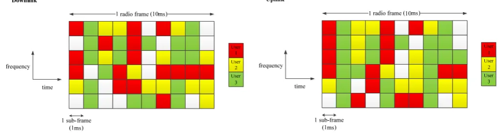
For each LTE sub-frame, the eNodeB must dynamically schedule the downlink (PDSCH) and uplink (PUSCH) resources in the frequency domain between the various users. Frequency domain resources are allocated on a block basis, where each block corresponds to 12 contiguous subcarriers (covering 180kHz). Individual users can be assigned zero, one or more blocks. On the downlink, if multiple blocks are assigned to a user, they can be contiguous or non-contiguous due to the use of OFDMA, but in the uplink, if multiple blocks are assigned to a user, they must be contiguous due to the use of SC-FDMA. Fig. 2 illustrates an example of such block resource assignment for the downlink and uplink.
The scheduling algorithm(s) are not specified in the LTE standards. eNodeB vendors design their own algorithms to differentiate themselves from their competitors. The scheduling algorithm must take multiple (sometimes competing) factors into account, such as system throughput, traffic profiles, fairness between users and the need to comply with contracted service level agreements (i.e. Quality-of-Service). A closely related concept is that of admission control in which the eNodeB decides whether to accept or reject a bearer request from a device at connection setup time based upon whether it believes it can comply with the requested QoS. The detailed design of the scheduling algorithm for a Smart Grid wireless network is likely to be different to that of a traditional wireless cellular network because of the unique traffic characteristics and QoS requirements. For example, voice traffic is unlikely to be very common in a Smart Grid wireless network, and most monitoring, control and protection traffic will have strict latency and QoS requirements.
LTE, like some previous wireless cellular systems, can exploit the time variability of a channel. For example, the eNodeB scheduler may schedule a user only in those sub-frames where the channel of the user is favorable. However, in addition, LTE can exploit the frequency variability of a channel. For example, the eNodeB scheduler may allocate a user one or more specific blocks in the frequency domain which correspond to a favorable channel for that user compared to other blocks. Furthermore, if multiple antenna technologies are in use for a particular user, the associated configuration can be dynamically changed. These scheduling options contribute to improved user and system performance at the expense of a more complex scheduling algorithm. This is true in a Smart Grid wireless system as well as a traditional wireless cellular system because the channels between the various devices and the eNodeB exhibit both time domain and frequency domain differences due in part to the fact that the devices have different locations each with unique environments from a radio perspective. The eNodeB needs to obtain appropriate channel state information from the device in a timely manner to make these enhanced scheduling decisions.
dow
nlin
k
The eNodeB indicates which users have downlink (PDSCH) or uplink (PUSCH) allocations on a downlink control channel known as the Physical Downlink Control CHannel (PDCCH) [16].
Fig. 2: Block Resource Assignment in Downlink and Uplink
2.4 Link Adaptation
Link adaptation refers to changing the modulation and coding rate for a particular user in sympathy with the instantaneous radio channel for that user [16]. It applies to both the downlink and uplink. For example, when the LTE radio channel is favorable, the eNodeB might schedule a user using 64QAM as the modulation so that 6 bits can be sent per symbol, whereas when the LTE radio channel is poor, the eNodeB might schedule a user using QPSK as the modulation for robustness against channel errors, but with the consequence that only 2 bits can be sent per symbol.
As with scheduling, the eNodeB needs to obtain appropriate channel state information from the device in a timely manner to adapt the link successfully. To support downlink link adaptation, the device sends Channel Quality Information (CQI) reports to the eNodeB periodically. To support uplink link adaptation, the device sends Sounding Reference Signals (SRS) to the eNodeB periodically.
Link adaptation is essential to optimizing user and system performance in a traditional LTE wireless system in which most devices are mobile and therefore possess time variant channels. It can be argued that it is less important in a Smart Grid wireless system because many devices are geographically fixed and therefore the time variability of their associated channels is less pronounced. One way to address this is to reduce the periodicity of the CQI reports and SRS signals for fixed devices via system configuration. Another method is to specify a threshold based reporting mechanism whereby the device only sends channel state information when the channel quality falls below a predefined threshold value. Both methods will reduce the signaling load on the network with little adverse impact for fixed devices.
2.5 Flexible Spectrum Usage
LTE supports both Frequency Division Duplex (FDD) and Time Division Duplex (TDD) modes of operation. With FDD, different spectrum allocations are used for the downlink and uplink so communication can occur on both simultaneously. With TDD, one spectrum allocation is used for the downlink and uplink so only one of the downlink and uplink can be active at any arbitrary time. FDD is typically used with paired spectrum allocations and TDD is typically used with unpaired spectrum allocations [18].
LTE also supports the following channel bandwidths: 1.4MHz, 3MHz, 5MHz, 10MHz, 15MHz and 20MHz to cater for spectrum allocations of different sizes in different bands and/or in different parts of the world [18]. It is expected that most Smart Grids will use channel bandwidths less than or equal to 10MHz and therefore our simulations focus on such typical bandwidths.
2.6 Transmission Time Interval (TTI) of 1ms
As illustrated in Fig. 2, blocks are allocated every frame in the time domain for both the downlink and uplink. One sub-frame corresponds to 1ms. This Transmission Time Interval (TTI) is smaller than earlier wireless systems (e.g. HSDPA uses a TTI of 2ms) and facilitates lower user plane data latency since data can be sent in a smaller transmission interval. Latency is a critical issue for some Smart Grid applications, particularly monitoring and control applications, so a short TTI is a key feature.
2.7 Hybrid ARQ (HARQ)
In LTE, both downlink and uplink data transmissions are acknowledged by the receiver at the physical layer. For example, for a downlink transmission from the eNodeB addressed to a specific device, the device will respond with either an ACK (if it decoded the packet correctly) or NACK (if it detected a residual error after decoding the packet) on the Physical Uplink Control Channel (PUCCH). If the device responds with a NACK, the eNodeB will retransmit the packet, as in traditional Adaptive Repeat reQuest (ARQ) that is used in many communication systems. The process continues until the device correctly decodes a retransmission (and in doing so returns an ACK to the eNodeB) or the maximum number of re-transmissions is reached.
correction. Furthermore, when the receiver detects a residual error in a packet after decoding it, it retains the packet for subsequent use in a combined decoding process with the re-transmissions. This procedure is known as Hybrid Adaptive Repeat reQuest (HARQ) [16] because it combines backward error correction (ARQ) with adaptive forward error correction.
In LTE, the HARQ Round Trip Time (RTT) is 8 sub-frames or 8ms. In the downlink, the HARQ process is asynchronous so a re-transmission can occur 8ms after the previous (re-)transmission, but it might take longer due to scheduling delays. In the uplink, the HARQ process is synchronous so a re-transmission always occurs exactly 8ms after the previous (re-)transmission.
HARQ is clearly important in a Smart Grid environment as it facilitates error free communication which is essential when communicating measurement data on the uplink and/or control commands on the downlink. However, it can result in significant additional delay due to re-transmissions of incorrectly decoded packets which is important for delay sensitive applications.
3 THEORETICAL ANALYSIS
In this section, we analyze the performance of a standard Release 8 LTE system used in a Smart Grid environment. We concentrate on two key areas: latency and channel utilization. The objective is to understand the strengths and weaknesses of standard LTE when applied to a typical Smart Grid monitoring scenario.
3.1 Latency
Latency is a key issue for Smart Grid monitoring and control as the stability of the Smart Grid depends upon being able to detect and act on anomalies as quickly as possible. As illustrated in Fig. 2, the LTE uplink and downlink both utilize a 10ms radio frame which is divided into ten 1ms sub-frames. The sub-frame is the minimum resource allocation unit in the time domain, so the minimum latency possible is 1ms. In practice, however, there are other sources of latency on the radio interface as illustrated in Fig. 3.
For the downlink, once data arrives for a specific device (or UE), the eNodeB must wait until the device wakes from its Discontinuous Reception (DRX) cycle in order to send the data to the device. DRX is a power saving feature in which the device listens to the eNodeB periodically during certain predefined intervals known to both the device and eNodeB, and sleeps in-between [16][17]. This improves the battery lifetime of the device at the expense of increased latency, since no downlink data can be sent while the device is asleep. The eNodeB knows the exact sub-frame when the device will wake up from its DRX cycle to receive buffered data, but depending upon chance, it might be in the very near future (even the next sub-frame) or almost a full DRX cycle into the future. Furthermore, the eNodeB may not send the data to the device on the PDSCH the first time it wakes up from its DRX cycle if there is congestion on the downlink and/or there is higher priority data to send to other devices. Therefore there can be an additional delay due to the eNodeB scheduling function.
For the uplink, once the device is ready to send data, it sends a Scheduling Request (SR) [17] on the PUCCH assuming it has not already been assigned an allocation on the PUSCH by the eNodeB. The SR is a flag that indicates to the eNodeB that this device has data ready to send, but it does not include any information on the volume or priority of data. As specified in [19], a device is only allowed to send an SR on the PUCCH at periodic intervals and is explicitly assigned an offset within the period for SR transmission purposes. The device of course knows the exact sub-frame corresponding to its next SR opportunity, but depending upon chance, it might be in the very near future (even the next sub-frame) or almost a full SR period into the future. On receiving the SR from the device, the eNodeB sends an uplink grant to the device on the PDCCH so that the device can send a data packet and/or indicate the volume and priority of data it has to send in the form of a Buffer Status Report (BSR) [17]. This may be subject to a scheduling delay at the eNodeB in cases of congestion. The fixed delay of 4 sub-frames from the device receiving its uplink grant from the eNodeB on the PDCCH to the device transmitting the uplink packet on the PUSCH is specified in [19].
There are other potential delays on both the downlink and uplink apart from the access delays just considered. For example, Fig. 3 assumes that the device has an active Radio Resource Control (RRC) connection i.e. it is in state RRC_CONNECTED as opposed to state RRC_IDLE [16][20]. A device which is in the RRC_IDLE state must first transition to the RRC_CONNECTED state before downlink or uplink data transmission can occur with a typical associated latency of 50-100ms. Another important source of delay occurs when a packet needs to be re-transmitted one or more times because it was not successfully decoded by the receiver (i.e. the device for a downlink packet and the eNodeB for an uplink packet). Finally, if the packet is sufficiently large that it needs to be split into one or more fragments which are sent in different sub-frames; this also creates an additional delay.
We concentrate on the LTE uplink in the following as a more detailed analysis is needed to support our simulation analysis later in the paper. In particular, when a re-transmission does occur on the LTE FDD uplink because the eNodeB could not successfully decode a packet, it adds a fixed delay of 8 sub-frames (8ms) to the end-to-end latency because the uplink Hybrid Adaptive Repeat reQuest (HARQ) process is synchronous with a fixed round trip time of 8ms [16][17][19]. Considering this and our previous analysis, a general equation for the LTE FDD uplink latency TUPLINK in sub-frames or milliseconds at the MAC
layer is as follows:
4 8 (1)
in which:
U1 is the number of sub-frames to the next Scheduling Request (SR) opportunity, and is a discrete random variable with a
discrete uniform distribution i.e. U1 ~ Un(1, SRPERIOD) where SRPERIOD is the configured Scheduling Request period and is one
of 5, 10, 20, 40 or 80 [19].
U2 is the number of sub-frames the eNodeB takes to respond to the Scheduling Request with an uplink grant on the PDCCH.
This depends upon a number of factors including instantaneous loading of the system and the eNodeB scheduler design. 4 is the fixed delay of 4 sub-frames from the device receiving its uplink grant to the device transmitting the uplink packet. 8 is the fixed delay of 8 sub-frames when a re-transmission occurs on the uplink.
is the number of HARQ re-transmissions required for the eNodeB to successfully decode the packet.
The equation (1) makes the following assumptions: a) the device is sending a relatively small packet which can be accommodated within the initial uplink grant, b) the device is in the RRC_CONNECTED state, and c) the device does not have a current PUSCH resource grant.
Note also that equation (1) relates to MAC layer latency. Therefore it does not account for higher layer re-transmissions that may occur, such as at the RLC layer when using Acknowledged Mode (AM) operation [21].
The best case uplink latency of 6ms occurs when U1 = 1 (by random chance), U2 = 1 (due to a lightly loaded system) and
0 (when the eNodeB can decode the original packet transmission successfully). If 1, the uplink latency increases to 6+8=14ms, if 2, the uplink latency increases to 14+8=22ms and so on. The default maximum number of re-transmissions is 4 by default (after which the packet is declared erroneous at the MAC layer and re-transmission must be handled through the RLC ARQ or higher layer functionality), although this can be changed through RRC signaling. In a mobile environment, we might expect the probability of 1 to be typically 0.1, and the probability of 2 to be typically 0.01 and so on. However, in a fixed application such as PMU measurement and reporting, the link budget can be more easily optimized by employing carefully positioned directional antennas for the PMUs with the result that the number of HARQ re-transmissions is reduced.
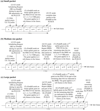
schedules a second uplink grant for the remaining data. However, both uplink grants are subject to the same fixed delay of 4 sub-frames (4ms) from the device receiving the grant on the PDCCH to the device transmitting the uplink packet on the PUSCH [19]. Therefore the best case uplink latency for a small packet is 6ms, but the best case uplink latency for a medium size packet (i.e. with a payload size of 40 bytes or larger for our example uplink scheduler) is 11ms as illustrated in Fig. 4(a) and (b) respectively. When the packet size increases further, there comes a point when more RB pairs are required to carry the packet. However, once the eNodeB is in possession of a BSR and therefore knows the total volume of data to be transmitted by the device, it can in principle make subsequent uplink grants in consecutive sub-frames as illustrated in Fig. 4(c), so the minimum delay only increases marginally to 12ms.
Fig. 4: Best Case Uplink Latency for Small, Medium and Large Packets
3.2 Channel Utilization
Many devices in a Smart Grid communications environment, such as sensors and control devices, will be sending and/or receiving small packets at infrequent intervals. LTE was not designed for these traffic patterns, rather it was designed to support voice and bursty data traffic in which individual users might send and/or receive relatively large packets (e.g. in connection with web browsing). Therefore there is a need to understand whether the LTE data and control channels can be utilized efficiently in a Smart Grid environment.
downlink and uplink data resources), the PDSCH downlink data channel and the PUSCH uplink data channel. First we calculate the number of users that can be scheduled on the PDCCH per sub-frame. As illustrated in Fig. 5, the PDCCH consumes all the Resource Elements (REs) in the first few OFDM symbols of each downlink sub-frame which are not otherwise allocated to the Physical Control Format Indicator Channel (PCFICH), Physical Hybrid ARQ Indicator Channel (PHICH) and cell specific reference signals. Note that the PDCCH and other downlink physical control channels are represented across the complete channel bandwidth i.e. across multiple Resource Block (RB) pairs, although this is not shown in Fig. 5.
Considering this, and using the same symbol terminology as the 3GPP LTE standards where appropriate [22], the number of REs available to the PDCCH within a downlink sub-frame, , is given by:
Fig. 5: PDCCH Resources
(2) in which:
is the number of OFDM sub-carriers per Resource Block (RB) and is fixed at 12 when using a normal cyclic prefix [22]. is the number of RB pairs available on the downlink, and is a function of the channel bandwidth [18].
is the number of OFDM symbols assigned to the PDCCH per sub‐frame, and is dynamically adjusted by the eNodeB in the range 2‐4 for a channel bandwidth of 1.4MHz and in the range 1‐3 for all larger channel bandwidths
22 .
is the number of Resource Elements REs assigned to the PCFICH within a downlink sub‐frame and is fixed at 16 22 .
is the number of REs assigned to the PHICH within a downlink sub‐frame. There are 12 REs allocated per PHICH group 22 , where the number of PHICH groups, , can be derived from a system parameter specified on the Physical Broadcast Channel PBCH 20 22 .
is the number of REs assigned to cell specific reference signals within the PDCCH region of each downlink sub‐ frame. This depends upon the transmission mode and in particular whether multiple transmit antennas are in use on the downlink 22 . For the single transmit antenna case, there are 2 reference symbols within the PDCCH region per RB
12
sub-carriers (180k
pair of each downlink sub‐frame, therefore 2 .
The maximum value of occurs when 3 (its maximum value) for any supported channel bandwidth larger than 1.4MHz. Considering the single transmit antenna case in the downlink, and substituting all constants and expressions from the explanation of Equation (2), we obtain:
max 36 16 12 2
34 16 12
(3) The eNodeB assigns uplink and downlink resources to individual devices using one or more PDCCH Control Channel Elements (CCEs), where each CCE corresponds to 36 Resource Elements [22]. Therefore the maximum number of CCEs, max , which also equals the maximum number of users that can be dynamically scheduled per sub-frame by the eNodeB, max , is given by:
max max 34 16 12
36
(4) It follows from (4) that:
max
(5) The significance of (5) is that if the eNodeB schedules the maximum number of users possible to each receive a small data packet which consumes 1 Resource Block pair per sub-frame on the downlink PDSCH, there will always be spare capacity remaining on the downlink PDSCH which the eNodeB cannot allocate because the PDCCH is saturated. In other words, the system capacity is control channel limited when users are sending/receiving small data packets, as is typical in a Smart Grid communications system.
If we consider both the uplink and downlink, the extent of the limitation on system capacity due to the PDCCH becomes even clearer when small data packets are involved. For example, for an LTE FDD configuration with a channel bandwidth of 5MHz,
25 [18], and assuming a typical figure of = 4 for this configuration, we obtain max 21 from (4). Therefore there are a maximum of 21 distinct users that can be scheduled per sub-frame. However, there are 25 available RB pairs in the downlink per sub-frame, and a typical figure of 21 available RB pairs in the uplink per sub-frame (assuming 4 RB pairs dedicated to the PUCCH), making a total of 46 RB pairs for data transfer. If each of the 21 users are sending/receiving small packets that only require 1 RB pair per sub-frame, only 21 of the available 46 RB pairs can be allocated with the remaining 25 RB pairs going unused due to PDCCH saturation. Even if each of the 21 users are sending/receiving larger packets that require 2 RB pairs per sub-frame, only 42 of the available 46 RB pairs can be allocated with the remaining 4 RB pairs going unused due to PDCCH saturation.
A distinct utilization issue in relation to small data packets is that the minimum resource allocation of 1 RB pair must still be employed to carry such packets even though only a fraction of the Resource Elements within the RB pair are actually occupied. In some cases, it may be beneficial to take advantage of this spare intra-RB capacity using more robust modulation and coding schemes for each device transmission than would otherwise be the case. There is also the possibility of devising new multiplexing and/or aggregation schemes to exploit this spare capacity for increasing system throughput.
4 SIMULATION
4.1 OPNET Simulation Environment
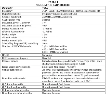
channel utilization measurement depends upon both uplink and downlink data usage. TABLE I lists the main parameters employed for the simulations.
TABLE I
SIMULATION PARAMETERS
Parameter Value
Frequency 3GPP Band I (1920MHz uplink, 2110MHz downlink) [18] Duplexing scheme Frequency Division Duplex (FDD)
Channel bandwidth 2x3MHz, 2x5MHz, 2x10MHz
Cyclic prefix type Normal
Maximum device Tx power 1W Maximum eNodeB Tx power 40W Device Rx sensitivity -110dBm eNodeB Rx sensitivity -123dBm
Device height 1.5m
eNodeB height 45m
Device antenna gain 4dBi
Scheduling Request (SR) periodicity 10ms
Number of PUCCH channels 2 (for 3MHz bandwidth) 4 (for 5MHz bandwidth) 8 (for 10MHz bandwidth)
HARQ Supported RRC measurement reports Disabled
Channel models Suburban fixed Erceg model with Terrain Type C [23] and a shadow fading standard deviation of 8.2dB.
Radio access network model Single cell, 5km radius (78.5km2)
Uplink traffic model An array of geographically fixed PMUs which are randomly placed in the cell and which simultaneously send UDP/IP packets with at a constant burst rate of 25 packets/second. Downlink traffic model UDP/IP packets with exponential inter-arrival times and a
mean burst rate of 5 packets/second to each PMU. QoS for uplink traffic Best effort on default bearer
QoS for downlink traffic Best effort on default bearer Uplink scheduler algorithm Dynamic fairness
Downlink scheduler algorithm Dynamic fairness
[image:10.595.174.420.546.586.2]Fig. 6 illustrates the uplink PMU packet structure which involves transmitting an IEEE C37.118 [24] packet over UDP/IP. The downlink control packet structure is identical except for the fact that an abstract control packet replaces the IEEE C37.118 packet for the payload.
Fig. 6: Uplink PMU Packet Structure When Transported over the LTE Air Interface
The PMU reporting rate of 25 packets/second is the highest mandatory such rate defined in IEEE C37.118 for a 50Hz electricity grid.
4.2 Performance as a Function of Load
Fig. 7 and Fig. 8 illustrate the mean end-to-end latency and mean PDCCH, PUSCH and PDSCH channel utilization respectively as a function of the number of synchronized PMUs and FDD channel bandwidth. Channel bandwidths of 2x3MHz, 2x5MHz and 2x10MHz are considered as these are likely to be the most relevant to an LTE network employed in a Smart Grid application. Since one of the primary objectives is to determine the best case uplink latency for the PMUs, a small IEEE C37.118 [24] payload of constant size 32 bytes was chosen to avoid fragmentation which might cause the fragments of a packet to be transmitted in different sub-frames, thereby increasing the measured delay. The size of the control payload for downlink packets was also set to a constant value of 32 bytes. We investigate the effect of packet size in the next section.
from our earlier theoretical analysis. As the channel bandwidth increases from 3MHz to 10MHz for a given load, there are more PDCCH resources on which to schedule PMU uplink transmissions and more PUSCH resources on which to carry PMU uplink transmissions per sub-frame, so the mean latency decreases. As the load increases from 20 to 200 PMUs for a given channel bandwidth, the transmissions of an increasing number of PMUs have to be delayed because there are limited and fixed PDCCH and PUSCH resources per sub-frame, therefore the mean latency increases in an approximately linear manner. The downlink latency remains almost constant at approximately 1.5ms for all bandwidths and loads; this is a reflection on the fact that the magnitude of the downlink traffic is relatively light in comparison to the magnitude of the uplink traffic. Note that our model did not implement DRX. This is because DRX is a feature which is primarily aimed at conserving power for battery powered devices at the expense of latency, while PMUs are unlikely to be battery powered (given the mission critical nature of the application) and minimal latency is a key application requirement.
Fig. 7: Mean Latency as a Function of Load (Payload Size = 32 bytes)
Fig. 8: Mean Channel Utilization as a Function of Load (Payload Size = 32 bytes)
The utilization figures in Fig. 8 represent the mean occupancy of the respective channels over all sub-frames. In the case of the PDCCH, the mean utilization is in respect of Control Channel Elements (CCEs), whereas in the case of the PDSCH and PUSCH, the mean utilization is in respect of uplink Resource Block (RB) pairs. The utilization figures represent the percentage of CCEs or RB pairs which are occupied, but do not indicate how efficiently each CCE or RB pair is being used. Note that the mean PDCCH utilization is higher than the mean PUSCH utilization for the same number of PMUs and same channel bandwidth. This implies that the PDCCH control channel becomes saturated before the PUSCH uplink data channel as we had earlier predicted in the theoretical discussion. This is significant because when the PDCCH is fully utilized during any arbitrary sub-frame so that the eNodeB cannot allocate any further resources on the PUSCH to waiting PMUs, the remaining available capacity on the PUSCH is wasted which results in additional delay to those waiting PMUs. We conclude that in a Smart Grid LTE FDD network in which there are a large number of devices transmitting small packets, the network performance is likely to be PDCCH limited rather than PUSCH limited.
[image:11.595.174.423.206.350.2]4.3 Performance as a Function of Payload Size
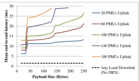
Fig. 9 and Fig. 10 illustrate the mean end-to-end latency and mean PDCCH, PUSCH and PDSCH channel utilization respectively as a function of IEEE C37.118 [24] payload size and the number of synchronized PMUs. The downlink control payload size is always identical to the uplink PMU payload size. These figures are for an LTE FDD system with a channel bandwidth of 2x5MHz. Recall from Fig. 6 that the IEEE C37.118 packet is transported over UDP/IP such that the total data volume carried by the LTE bearer is 28 bytes larger than illustrated.
0 2 4 6 8 10 12 14 16 18 20
0 50 100 150 200
Mean end-to-e
nd late
ncy
(m
s)
Number of PMUs
3MHz Uplink 5MHz Uplink 10MHz Uplink 3MHz, 5MHz and 10MHz Downlink (No DRX) 0 10 20 30 40 50 60 70
0 50 100 150 200
Mean c h an n el u ti lizat ion ( % )
Number of PMUs
Fig. 9: Mean Latency as a Function of Payload Size (Channel Bandwidth = 2x5MHz)
Fig. 10: Mean Channel Utilization as a Function of Payload Size (Channel Bandwidth = 2x5MHz)
It can be seen from Fig. 9 that there is a sharp jump in mean uplink latency of at least 5ms when the IEEE C37.118 packet size increases from 32 to 40 bytes. This is consistent with the analysis of Section 3.1 in moving from a small to a medium sized packet for our example eNodeB scheduler, because the eNodeB must perform two separate uplink grants for a payload size of 40 bytes, with the second uplink grant following the first by no less than 5ms.When the packet size increases to approximately 144 bytes, there is another jump in latency, although not as sharp. Again this is consistent with the analysis of Section 3.1 in moving from a medium to a large sized packet for our example eNodeB scheduler, because the eNodeB must perform three separate uplink grants for a payload size of 144 bytes, with the second uplink grant following the first by no less than 5ms and the third uplink grant following the second by at least 1ms.
In Fig. 10, we can see that the mean PDCCH utilization is higher than the mean PUSCH utilization for small packet sizes, but as the packet size increases, there is a crossover point after which the mean PUSCH utilization is higher than the mean PDCCH utilization. This is to be expected because as the packet size increases, the mean number of PUSCH RB pairs allocated by the eNodeB per uplink grant on the PDCCH increases, thereby increasing the mean PUSCH utilization relative to the mean PDCCH utilization. As discussed previously, many Smart Grid devices will send and receive small packets, so there is a strong potential for the system capacity to be PDCCH limited.
5 PMUPACKET PAYLOAD FORMAT AND SIZE
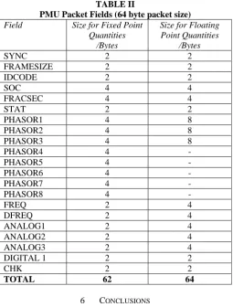
[image:12.595.176.421.81.224.2]With reference to the IEEE PMU standard C37.118 [24], a 64 byte payload size for PMU packets is sufficient to accommodate 3 phasor measurements in floating point representation or 8 phasor measurements in fixed point representation as illustrated in TABLE II. This assumes the inclusion of 3 ANALOG fields and 1 DIGITAL field in each packet.
As discussed in Section 4.3, an IEEE C37.118 packet of size 32 bytes carried over UDP/IP/LTE has a best case uplink latency of 6ms, whereas an IEEE C37.118 packet of size 64 bytes carried over UDP/IP/LTE has a best case uplink latency of 11ms. Therefore it may be important to use application layer compression or IP header compression in a real deployment to allow data on a sufficient number of phasors to be reported with the minimum latency.
0 5 10 15 20 25 30
0 50 100 150 200 250
M ea n en d-to -end la tency (ms)
Payload Size (Bytes)
20 PMUs Uplink 60 PMUs Uplink 100 PMUs Uplink 140 PMUs Uplink 180 PMUs Uplink Any Load Downlink (No DRX) 0 10 20 30 40 50 60 70 80 90 100
0 50 100 150 200 250
M ean ch ann el uti lizati o n (% )
PMU Packet Size (Bytes)
TABLE II
PMU Packet Fields (64 byte packet size)
Field Size for Fixed Point
Quantities /Bytes
Size for Floating Point Quantities
/Bytes
SYNC 2 2
FRAMESIZE 2 2
IDCODE 2 2
SOC 4 4
FRACSEC 4 4
STAT 2 2
PHASOR1 4 8
PHASOR2 4 8
PHASOR3 4 8
PHASOR4 4 -
PHASOR5 4 -
PHASOR6 4 -
PHASOR7 4 -
PHASOR8 4 -
FREQ 2 4 DFREQ 2 4
ANALOG1 2 4
ANALOG2 2 4
ANALOG3 2 4
DIGITAL 1 2 2
CHK 2 2
TOTAL 62 64
6 CONCLUSIONS
In this paper, we have analyzed the performance (and in particular the latency and channel utilization) of a standard Release 8 LTE FDD wide area communications system for use in a Smart Grid communications scenario. It was demonstrated both through analysis and simulation that the minimum possible uplink latency is 6ms for a small application packet (with a payload size of less than 40 bytes carried over UDP/IP for our example scheduler), and 11ms for a larger application packet (with a payload size of 40 bytes or more carried over UDP/IP for our example scheduler). This assumes the device is already in the RRC_CONNECTED state. However, there are various factors which might increase the actual delay experienced, including the instantaneous loading of the system, poor channel conditions resulting in packet re-transmissions, and the fact a device must wait for its assigned Scheduling Request opportunity to indicate to the eNodeB that it has data to send, which is a source of random delay and can be as high as 80ms depending upon the system configuration.
We also demonstrated both through analysis and simulation that the capacity of an LTE FDD network is PDCCH control channel limited when there are many devices attempting to send or receive small packets as in a Smart Grid environment. This is undesirable from an efficiency perspective because it results in some data channel capacity going unused even if there is traffic waiting to be sent, and because it increases mean packet delay.
Areas for further research include a) analyzing the effect of different types of Smart Grid traffic (with different QoS requirements) on the performance of the LTE network, b) designing new radio resource algorithms (particularly eNodeB scheduling algorithms) to reflect the unique nature of Smart Grid traffic types, c) examining the relationship between physical layer HARQ and RLC layer ARQ for typical Smart Grid applications with a view to determining whether both are required, and d) determining how the spare capacity of Resource Block pairs which are only partially used due to the transport of small application packets in Smart Grid applications can be efficiently exploited (e.g. via data aggregation or using more robust modulation and coding schemes).
ACKNOWLEDGEMENTS
This work has been supported by Ausgrid and the Australian Research Council (ARC). REFERENCES
[1] Xinghuo Yu, Carlo Cecati, Tharam Dillon and M. Godoy Simoes, “The New Frontier of Smart Grids – An Industrial Electronics Perspective”, IEEE Industrial Electronics Magazine, September 2011, pp. 49-63.
[3] Fangxing Li, Wei Qiao, Hongbin Sun, Hui Wan, Jianhui Wang, Yan Xia, Zhao Xu and Pei Zhang, “Smart Transmission Grid: Vision and Framework”, IEEE Transactions On Smart Grid, Vol. 1, No. 2, September 2010, pp. 168-177
[4] Amar Patel, Juan Aparicio, Nazif Tas, Michael Loiacono and Justinian Rosca, “Assessing Communications Technology Options for Smart Grid Applications”, Smart Grid Communications (SmartGridComm), 2011 IEEE International Conference on, 2011, pp. 126-131
[5] Jun Wang and Victor C. M. Leung., “A survey of technical requirements and consumer application standards for IP-based smart grid AMI network”, Information Networking (ICOIN), 2011 International Conference on, 2011, pp. 114 – 119. [6] Yingchen Zhang et al., “Wide-Area Frequency Monitoring Network (FNET) Architecture and Applications”, Smart Grid,
IEEE Transactions on, Volume: 1, Issue: 2, September 2010, pp. 159 – 167.
[7] Anjan Bose, “Smart Transmission Grid Applications and Their Supporting Infrastructure”, IEEE Transactions On Smart Grid, Vol. 1, No. 1, June 2010, pp. 11-19.
[8] Thilo Sauter and Maksim Lobashov, “End-to-End Communication Architecture for Smart Grids”, IEEE Transactions on Industrial Electronics, Vol. 58, No. 4, April 2011, pp.1218-1228.
[9] Wenye Wang,, Yi Xu and Mohit Khanna “A survey on the communication architectures in smart grid”, The International Journal of Computer and Telecommunications Networking, Volume 55, Issue 15, 27 October 2011, Pages 3604–3629. [10]Shao-Yu Lien, Kwang-Cheng Chen and Yonghua Lin, “Toward Ubiquitous Massive Accesses in 3GPP
Machine-to-Machine Communications”, IEEE Communications Magazine, April 2011.
[11]Vehbi C. Gungor and Gerhard P. Hancke, “Opportunities and Challenges of Wireless Sensor Networks in Smart Grid”, IEEE Transactions On Industrial Electronics, Vol. 57, No. 10, October 2010, pp. 3557-3564
[12]Palak P. Parikh, Mitalkumar. G. Kanabar, Tarlochan S. Sidhu., “Opportunities and challenges of wireless communication technologies for smart grid applications”, IEEE Power and Energy Society General Meeting, 2010.
[13]3GPP TR 25.913 V8.0.0 (2008-12), “Requirements for Evolved UTRA (E-UTRA) and Evolved UTRAN (E-UTRAN)", Release 8
[14]Zhao Feng, Liu Jianming, Hu Dan, Zhang Yuexia, “Study on the application of advanced broadband wireless mobile communication technology in smart grid”, Power System Technology (POWERCON), 2010 International Conference on, 2010.
[15]Peng Cheng, Li Wang, Bin Zhen, Shihua Wang, “Feasibility Study of Applying LTE to Smart Grid”, IEEE First International Workshop on Smart Grid Modeling and Simulation (SGMS) - IEEE SmartGridComm 2011
[16]3GPP TS 36.300 V8.12.0 (2010-03), “Evolved Universal Terrestrial Radio Access (E-UTRA) and Evolved Universal Terrestrial Radio Access Network (E-UTRAN); Overall description; Stage 2”, Release 8
[17]3GPP TS 36.321 V8.10.0 (2011-09), “Evolved Universal Terrestrial Radio Access (E-UTRA); Medium Access Control (MAC) protocol specification”, Release 8
[18]3GPP TS 36.101 V8.16.0 (2011-12), “Evolved Universal Terrestrial Radio Access (E-UTRA); User Equipment (UE) radio transmission and reception", Release 8
[19]3GPP TS 36.213 V8.8.0 (2009-09), “Evolved Universal Terrestrial Radio Access (E-UTRA); Physical layer procedures”, Release 8.
[20]3GPP TS 36.331 V8.15.0 (2011-09), “Evolved Universal Terrestrial Radio Access (E-UTRA); Radio Resource Control (RRC); Protocol specification”, Release 8.
[21]3GPP TS 36.322 V8.8.0 (2010-06), “Evolved Universal Terrestrial Radio Access (E-UTRA); Radio Link Control (RLC) protocol specification”, Release 8
[22]3GPP TS 36.211 V8.9.0 (2009-12), “Evolved Universal Terrestrial Radio Access (E-UTRA); Physical Channels and Modulation", Release 8
[23]V. Erceg et al., “An empirically based path loss model for wireless channels in suburban environments”, IEEE JSAC, vol.17, no.7, July 1999, pp. 1205-1222.
![Fig. 9 and Fig. 10 illustrate the mean end-to-end latency and mean PDCCH, PUSCH and PDSCH channel utilization respectively as a function of IEEE C37.118 [24] payload size and the number of synchronized PMUs](https://thumb-us.123doks.com/thumbv2/123dok_us/152808.29952/11.595.174.423.206.350/illustrate-latency-channel-utilization-respectively-function-payload-synchronized.webp)