i
“I hereby, declare that I have read this thesis and in my opinion this thesis is sufficient in terms of scope and quality for the award of degree of Bachelor of Electrical Engineering
(Power Electronics & Drives)
i
A MODIFICATION OF DIRECT TORQUE CONTROL FOR HIGH- EFFICIENCY AND QUICK RESPONSES INDUCTION MACHINE
DIEZA FAYYADHA BINTI KAMARUDIN
A project report submitted in partial fulfillment of the requirement for a ward of the degree of Bachelor of Electrical Engineering (Power Electronics & Drives)
Faculty of Electrical Engineering Universiti Teknikal Malaysia Melaka
ii
I declare that this thesis entitled “A Modification of Direct Torque Control for High- Efficiency and Quick Responses Induction Machine” is the result of my own research except
for works that have been cited in the reference. The thesis has not been accepted any degree and not concurrently submitted in candidature of any other degree.
iii
iv
ACKNOWLEDGEMENT
Alhamdulillah, I am grateful to Allah SWT on His blessing in completing this project. I would like to express my gratitude to honourable Dr. Auzani bin Jidin, my supervisor of Bachelor’s project. Under his supervision, many aspects regarding on this project has been explored, and with the knowledge, idea and support received from him, this thesis can be presented in the time frame given.
Finally, I would like to dedicate my gratitude to my parents, my family and friends especially my classmate Nurul Adibah, Nur Affiqah, Nur Aqeela and Che Wan Nur Athifah and who helped me directly or indirectly in the completion of this project. Their encouragement and guidance mean a lot to me. Their sharing and experience foster my belief in overcoming every obstacle encountered in this project.
Guidance, co-operation and encouragement from all people above are appreciated by me in sincere. Although I cannot repay the kindness from them, I would like to wish them to be well and happy always.
v
ABSTRAK
vi
ABSTRACT
vii
TABLE OF CONTENTS
CHAPTER SUBJECT PAGES
TITLE i
DECLARATION ii
DEDICATION iii
ACKNOWLEDGEMENT iv
ABSTRAK v
ABSTRACT vi
TABLE OF CONTENTS vii
LIST OF TABLES x
LIST OF FIGURES xi
LIST OF APPENDICES xiii
1 INTRODUCTION
1.1 Research Background 1
1.2 Problem Statement 2
1.3 Objective of Research 3
1.4 Scopes of Research 3
1.5 Research Methodology 4
1.5.1 Literature Review 6
1.5.2 Experimental Set-up 6
viii
2 LITERATURE REVIEW
2.1 Introduction 8
2.2 Direct Torque Control of Induction Machine based on
Circular Flux Control 8
2.3 Direct Torque Control of Induction Machine based on
Hexagonal Flux Control 11
2.3.1 Direct Self Control (DSC) 11
2.3.2 DTC with Dual-Mode Flux Control 14
2.4 Conclusion 15
3 METHODOLODY
3.1 Introduction 16
3.2 Development of the Basic DTC Control Algorithm 16 3.2.1 Calculation of d- and q- Axis Voltage Components 17 3.2.2 Calculation of d- and q- Axis Stator Currents 20 3.2.3 Estimation of Stator Flux and Electromagnetic
Torque 21
3.2.4 Detection of Sector 22
3.2.5 Torque Hysteresis Control 26
3.2.6 Flux Hysteresis Control 27
3.2.7 Voltage Vector Selection Table 28
3.3 Formulation of the Modified DTC 29
3.3.1 A New Sector Definition 29
3.3.2 Updated Sector 30
3.4 Verification via Experimentation 31
3.4.1 I/O Terminals for DSPACE1104 33
3.4.2 Level Shifter and Buffer Circuit 34
3.4.3 Hall Effect Current Sensor 35
ix
3.4.5 Induction Machine 36
3.5 Conclusion 38
4 RESULTS AND DISCUSSION
4.1 Introduction 39
4.2 Performance Analysis of Switching Frequency 40 4.3 Performance Analysis on Torque Control Capability 43
4.4 Analysis Sector Deviation 44
4.5 Ideal and Practice Cases 49
4.6 Conclusion 50
5 CONCLUSION 51
REFERENCES 53
x
LIST OF TABLES
TABLE
NUMBER TITLE PAGE
3.1 Description of torque selecting appropriate voltage vectors 26
3.2 Voltage vector selection table (LUT – DTC) 29
xi
LIST OF FIGURES
FIGURE
NUMBER TITLE PAGE
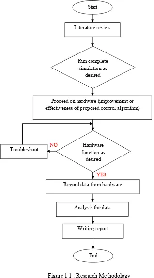
1.1 Research Methodology 5
2.1 Schematic of DTC based induction machine 9
2.2 A circular flux control with suitable voltage vector application 11
2.3 Schematic of DSC based induction machine 12
2.4 A hexagonal flux control with suitable voltage vector application 13
2.5 A structure of DTC with dual-mode flux control 14
3.1 An original DTC structure of induction machine 17
3.2 A three-phase voltage source inverter connected to 3-phase
induction machine 19
3.3 Voltage space vector of a 3-phase inverter with the corresponded
switching states 20
3.4 Definition of six sectors of the stator flux plane 22
3.5 Calculation of threshold for sector detection 23
3.6 Flow chart of sector detection 25
3.7 Control of torque using three-level hysteresis comparator 27 3.8 Control of flux using two-level hysteresis comparator 27
3.9 Basic structure of DTC 28
3.10 The new sector development 30
3.11 Updated sector block 31
3.12 Experimental set-up 32
3.13 Complete hardware of DTC drive system 32
xii
3.15 PCB board of I/O terminal of DSPACE1104 33
3.16 Level shifter and buffer circuit with FPGA hardware 34
3.17 Hall effect current sensor hardware 35
3.18 Gate driver and 3-phase inverter (VSI) 36
3.19 The coupling of induction machine(left) and DC machine(right) 37 3.20 Complete experimental platform of modified DTC drive system 37 4.1 d-q flux, torque estimator and phase voltage, Va (a) DTC (b)
Modified DTC
41
4.2 Magnified image of d-q flux, torque estimator and phase voltage, Va (a) Conventional DTC scheme (b) Modified DTC scheme
42
4.3 Flux locus (a) Circular shape by conventional DTC scheme (b) Hexagonal shape by modified DTC scheme
43
4.4 Torque control during modified DTC and conventional DTC operation
44
4.5 Selection of voltage vector 45
4.6 Deviation angle by proposed strategy (a) Low Speed (b) High Speed
46
4.7 Performance of speed in proposed strategy (a) Low Speed (b) High Speed
48
4.8 The motion of flux vector through (a) Ideally case (b) Practically case
49
4.9 The waveform of output torque by selection of two vector for (a) low speed (b) high speed
xiii
LIST OF APPENDICES
APPENDICES TITLE PAGES
A Gantt Chart 55
1
CHAPTER 1
INTRODUCTION
1.1 Research Background
Not until 1970s, the induction motor extensively employed a scalar control method to obtain desired motor speeds, by controlling the magnitude and frequency of AC voltage. The control of the magnitude and frequency of AC voltages is made such that the ratio of the magnitude to the frequency is constant, so that the rated flux can be produced in order to achieve higher torque capability. Despite its simplicity of control technique, the control of speed is only valid on steady state operations. The method results in poor dynamic control performances and unable to reject any disturbance (i.e. load torque application or variation on motor parameters) that degrades the control performances.
2
transformations, current controllers (or space voltage vector modulator) and speed sensor. Later, around middle of 1980’s, Takahashi introduced a simple technique which is called Direct Torque Control (DTC) [2][3] that is based on hysteresis controllers and switching voltage vectors table. After a few years later, a similar concept of control was proposed by Dapenbrock which is referred to as Direct Self Control (DSC) [4]; that operates the flux locus into hexagonal shape to obtain superior torque dynamic control.
Until now, further improvement of motor control performances still receives high attentions for fulfilling important requirements, e.g. high-efficiency and excellent dynamic control performances, especially in traction or electric vehicle applications. Some modifications on FOC or DTC were proposed with the use of multilevel inverters [5], more intelligent control approaches (e.g. fuzzy logic controller [6] and predictive control [7]) and other types of motor [8].
1.2 Problem Statement
Despite the DTC simplicity, it may produce high switching frequencies due to the excessive switching which might occur in the hysteresis controller. Note that, the switching frequency of inverter is influenced by the switching in torque and flux hysteresis controllers.
3
or decrease the flux becomes more often and significant as the duration of zero vector application to halt the flux is short.
It is emphasized that the switching frequency that exceeds beyond the limitation of switching devices will degrade the performance of switching, in terms of blocking/conducting capability and efficiency.
1.3 Objectives of Research
There are two objectives to accomplish this research which are as follows:
1. To minimize switching frequency and hence switching losses by modifying the DTC structure so that flux locus can be controlled to form a hexagonal shape.
2. To verify the operation of the modified DTC and its improvements via experimental results.
1.4 Scopes of Research
4
1.5 Research Methodology
5
Figure 1.1 : Research Methodology Start
Literature review
Run complete simulation as
desired
Proceed on hardware (improvement or effectiveness of proposed control algorithm)
Hardware function as
desired Troubleshoot
Record data from hardware
Analysis the data
Writing report
End
NO
6
1.5.1 Literature Review
For this section will review the summary and synthesize the idea of other publisher of journal or technical report related to DTC, but more concentrating on the switching frequency of direct torque control of induction machines. In order, to understand all the entire DTC algorithm.
1.5.2 Experimental Set-up
After the simulation design of DTC complete with a modification structure, now the hardware installation was proceed. The VHDL code of look-up table and blanking time generators will be developed for complied into FPGA. If there any problems with the hardware installation, process of troubleshoot on the hardware for solving the problem will conducted until the hardware is functional as desired.
1.6 Outline of Thesis
Below are the brief descriptions for the rest chapters:
7
Chapter 3 explains the method to realize the modified DTC algorithms which retain the most part of DTC conventional scheme. The related mathematical modelling will be discussed to clearly understanding of DTC algorithm. This chapter also explains the implementation of hardware which to verify the improvement or effectiveness of proposed control algorithm.
Chapter 4 will presents and analyzes the experimental results that tested under same conditions in terms of speed and load torque to get the ideal comparison. Thus, evaluation is done by experimental platform.
8
CHAPTER 2
LITERITURE REVIEW
2.1 Introduction
In this chapter, some previous works related to the research project will be reviewed to analyze and compare in terms of principle strategy and performance improvement. In general, the review emphasizes some DTC strategies that improve the power efficiency and torque dynamic control by selecting suitable voltage vectors for each control of flux; either performs the circular or hexagonal flux shape.
2.2 Direct Torque Control of Induction Machine based on Circular Flux Control
9
voltage vectors in the look-up table in restricting the errors within their respective hysteresis bandwidths.
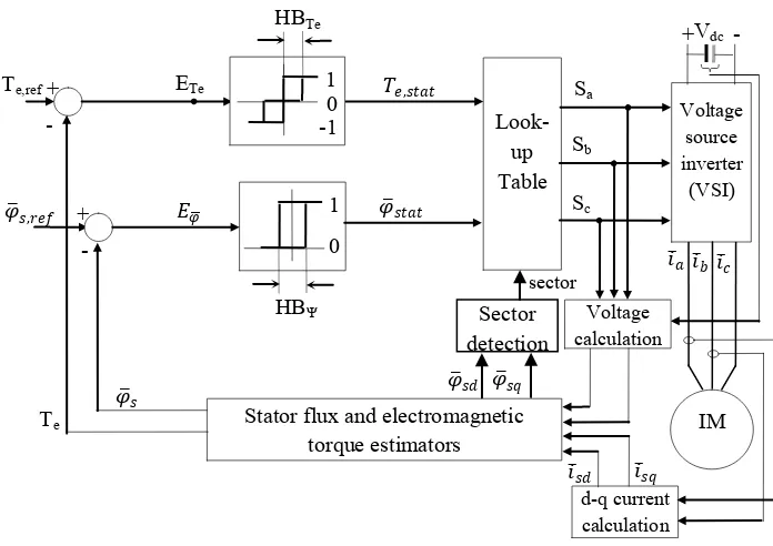
Figure 2.1 : Schematic of DTC based induction machine
In [2], the flux space vector is controlled such that its locus forms into a circular shape by selecting suitable active voltage vectors for every sector of flux. Taking into account that the change of flux vector (∆𝜑 ) is mainly influenced by applied voltage vectors (𝑣 𝑠𝑛) as the ohmic
drop voltage can be assumed to be neglected:
∆𝜑
= 𝑣 𝑠𝑛. ∆𝑡 (2.1)
As shown by Figure 2.2, a different set of two active voltage vectors is switched for every flux sector to form a circular flux locus, either in counter clockwise or clockwise rotation. For example, considering the flux vector has just entered into Sector II (i.e. from Sector I) and it has to move towards the Sector III; it can be noticed that the voltage vector 𝑣 𝑠3
is the most tangential component to flux locus at the boundary of Sector I and II, while the voltage vector 𝑣 𝑠4 is the most tangential component to flux locus at the boundary of Sector II
d-q current calculation
Te,ref
𝜑 𝑠,𝑟𝑒𝑓
Look-up Table Voltage source inverter (VSI) + IM Sa Sb Sc 𝜑 𝑠𝑑 Stator flux and electromagnetic
torque estimators -
+ -
Te 𝜑 𝑠
𝜑 𝑠𝑡𝑎𝑡 𝑇𝑒,𝑠𝑡𝑎𝑡
𝑖 𝑏𝑖 𝑐 Vdc
𝑖 𝑎
Voltage calculation 𝜑 + - 0 1 -1 HBTe 0 1 HBΨ 𝐸𝜑 ETe Sector detection sector
𝜑 𝑠𝑞
[image:23.612.144.492.113.359.2]10
and III. Note that, the voltage vector that has the most tangential to flux locus is the most effective voltage vector that produces the maximum amplitude as well as angular velocity of flux vector. This is why these two voltage vectors 𝑣 𝑠3and 𝑣 𝑠4 are identified and chosen as the
suitable voltage vectors when the flux vector is controlled in Sector II. In this sector, according to (2.1), the selection of 𝑣 𝑠3will increase the flux magnitude, otherwise the selection
of 𝑣 𝑠4 will decrease the flux magnitude.
The control of circular flux locus may cause high switching frequency since the switching of active vectors will become more often, especially at high speed operations. During high speeds, the angular velocity of flux vector needs to be increased to maintain the capability of torque [9] in which the number application of zero vector that ideally halt the flux has to be reduced. Thus, selection of active vectors would be dominated and switched more often as the motor speed increases.