VISION SYSTEM BASED HEIGHT MEASURING MACHINE
ROZEANA BINTI ABD RAHMAN
This report is submitted in partial fulfilment of the requirement for the award of Bachelor of Electronic Engineering (Industrial Electronic) With Honours
Faculty of Electronic and Computer Engineering University Technical Malaysia Melaka
UNIVERSTI TEKNIKAL MALAYSIA MELAKA
FAKULTI KEJURUTERAAN ELEKTRONIK DAN KEJURUTERAAN KOMPUTER
BORANG PENGESAHAN STATUS LAPORAN
PROJEK SARJANA MUDA II
Tajuk Projek : Vision System Based Height Measuring Machine
Sesi
Pengajian : 0 9 / 1 0
Saya ROZEANA BINTI ABD RAHMAN
(HURUF BESAR)
mengaku membenarkan Laporan Projek Sarjana Muda ini disimpan di Perpustakaan dengan syarat-syarat kegunaan seperti berikut:
1. Laporan adalah hakmilik Universiti Teknikal Malaysia Melaka.
2. Perpustakaan dibenarkan membuat salinan untuk tujuan pengajian sahaja.
3. Perpustakaan dibenarkan membuat salinan laporan ini sebagai bahan pertukaran antara institusi
pengajian tinggi.
4. Sila tandakan ( √ ) :
SULIT*
*(Mengandungi maklumat yang berdarjah keselamatan atau kepentingan Malaysia seperti yang termaktub di dalam AKTA RAHSIA RASMI 1972)
TERHAD** **(Mengandungi maklumat terhad yang telah ditentukan oleh organisasi/badan di mana penyelidikan dijalankan)
TIDAK TERHAD
Disahkan oleh:
__________________________ ___________________________________ (TANDATANGAN PENULIS) (COP DAN TANDATANGAN PENYELIA)
iii
“I hereby declare that this report is result of my own effort except for works that have been cited clearly in the references.”
Signature :
Name : ROZEANA BINTI ABD RAHMAN
iv
“I hereby declare that I have read this report and in my opinion this report is sufficient in terms of scope and quality for the award of Bachelor of Electronic
Engineering (Electronic Telecommunication) with Honours”
Signature : ……….
Supervisor’s Name : EN. KHAIRUL AZHA B. ABD. AZIZ
v
ACKNOWLEDGEMENTS
In the name of Allah, invocation and greetings to adoration of Nabi Muhammad (S.A.W.), thanks to God because giving me strength and patience in finishing. Final Year Project (Projek Sarjana Muda). Alhamdulillah.
In particular, I wish to express my sincere appreciation to my supervisor, Mr. En. Khairul Azha Bin A. Aziz, for encouragement, guidance, critics and friendship. My fellow friends under the same supervisor should also be recognized for their support and ideas.
I sincerely appreciated all of the efforts and precious time to be spent together in making this final year project educational, enjoyable and memorable. Not to be forgotten, my deepest thanks to my parents for all the support and blessings.
vi
ABSTRACT
vii
ABSTRAK
viii
CONTENT
CHAPTER TITLE PAGE
PROJECT TITLE i
VERIFICATION FORM STATUS REPORT ii
DECLARATION iii
SUPERVISOR VERIFICATION iv
ACKNOWLEDGEMENT v
ABSTRACT vi
ABSTRAK vii
CONTENTS viii
LIST OF FIGURE xii
LIST OF TABLE xiii
I INTRODUCTION 1.1 Introduction 1 1.2 Project Objective 2 1.3 Scope of Project 2
1.4 Problem Statement 3
ix
2.2 Machine Vision System 4
2.3 The advantages of Matlab 6
2.4 Image Processing 7
2.4.1 Image Processing in Matlab 7
2.4.1.1 Image conversion 8
2.4.1.2 Thresholding 9 2.4.1.3 Edge detector 11
2.4.1.4 Sobel edge detector 12
2.4.1.5 Mophological image processing 13
2.4.1.6 Arithmetic operation 14
2.4.1.7 Complement image 15 2.5 Height measuring method 16 2.5.1 Manual 16 2.5.2 Automatic 17 2.5.3 Comparison measuring in manual and automatic 19
III METHODOLOGY
3.1 Block diagram of the system 20
3.2 Flow chart of project 21
3.3 Design methodology 23
3.4 Software development 24
3.4.1 Command 24
3.4.2 Webcam interaction 24
3.4.3 Image acquisition 25
3.4.4 Image Conversion 26
3.4.5 Image Segmentation (Thresholding) 26
3.4.6 Edge detector 26
3.4.7 Mophological image processing 27
3.5 Measurement process 28
x
4.1 Experimentation analysis and result 30
4.1.1 Webcam interaction and image capturing 32 4.1.2 Wall size measurement in pixel value 33
4.1.3 Image processing and height measurement on the 34
bottles plastic. 4.1.3.1 Image processing on the bottles 34
4.1.3.2 Height measurement on the bottle s 37
4.1.4 Image Processing and Height Measurement on 39
Shoes Boxes 4.1.4.1 Image processing on the shoes box 39
4.14.2 Height measurement 41
4.1.5 Percentage error and percentage accuracy 43
4.2 Discussion 47
V CONCLUSION AND RECOMMENDATION 5.1 Conclusion of this project 49 5.2 Recommendation 50
REFERENCES 51
APPENDIX 53
xi
LIST OF FIGURE
NO TITLE PAGE
2.1 Machine vision systems 6
2.2 RGB image to gray scale image 9
2.3 RGB image to black and white image 10
2.4 Edge image 11
2.5 Sobel filter 12
2.6 Complement image 15
2.7 Measuring by using Caliper 16
2.8 Measuring by using Height Gauge 16
2.9 Measuring by using stainless ruler 17
2.10 Coordinates Measuring Machine (CMM) 18
2.11 Camera and touch probe use for measuring 18
3.1 Block diagram vision system based height measuring machine 20
3.2 Flow Chat of Project 22
3.3 Design Methodology of Project 23
3.4 Image in Figure 25
3.5 The wall image processing 28
3.6 The size of wall in pixel value 29
3.7 The size of product in pixel value 29
4.1 Webcam interaction 32
4.2 Capturing Image 32
xii
4.4 The wall size in pixel value 33
4.5 Image processing on Bottle A 34
4.6 Cropped the image (Bottle A) 35
4.7 Image processing on Bottle B 35
4.8 Cropped the image (Bottle B) 36
4.9 Image processing on Bottle C 36
4.10 The command for height measurement 37
4.11 The height value of Bottle A 37
4.12 The height value of Bottle B 38
4.13 The height value of Bottle C 38
4.14 The boxes image 39
4.15 Image processing in Matlab on Shoes Box A 39
4.16 Cropped the box image (Shoes box A) 40
4.17 Image processing in Matlab on Shoes Box B 40
4.18 Cropped the box image (Shoes box A) 41
4.19 The height value of Shoes Box A 41
xiii
LIST OF TABLE
NO TITLE PAGE
2.1 The image or graphics format 8
2.2 List rules for dilation and erosion 13
2.3 Arithmetic function 14
2.4 Comparison measuring in manual and automatic 19
4.1 List of the product 31
CHAPTER 1
INTRODUCTION
1.1 Introduction
2
1.2 Project Objective
The objective of this project is to develop a system that can measure the height of the product using vision based system. The system will detect acquire the image of the product and display the length value on the screen. This project is to design a system which can process the image of product to measure the length of the product. The system will be developed using Matlab. Besides that, this project also able to:
To apply Matlab programming for image processing.
To apply and improve the knowledge about image processing which are
widely used in so many analysis applications.
1.3 Scopes of Project
3
1.4 Problem Statement
In the market there is so much equipment to measure height, but to get the exact measurement is difficult. Many measurements have done manually by the operator. When the measurement is done manually, then there are the less accurate the reading. This is because there was an error operators take readings. Besides that the measurement have done manually causing wastage of time and energy to get a reading because the operator had to take accurate readings repeatedly. There are also operators who forget to criticize the readings taken. To make measurements automatically, there are also factories produce a large expense to buy the best machine to get accurate measurement readings. Vision System Based Height Measuring Machine is proposing to solve these problems. The system is friendly user and requires only webcam and Matlab software to drive the system.
1.5 Report Overview
The Vision System Based Height Measuring Machine report is a combination of 5 chapters that contains and elaborates specific topics such as the Introduction, Literature Review, Methodology, Results and Discussions, Conclusion and Further Development that can be applied in this project.
Chapter 1: Introduction of the project.
Chapter 2: Literature review for the development of the Vision System Based
Height Measuring Machine.
Chapter 3: Methodology of the project.
Chapter 4: The project finding such as progress result and analysis of the image
processing to measuring the height of product.
CHAPTER 2
LITERATURE REVIEW
2.1 Vision System
A vision system is capable of magnifying their vision multiple times and may catch imperfections and flaws indiscernible to the human eye. A vision system can inspect at a much higher rate than human eyes and are more precise and consistent than the human workforce they often replace. A vision system is an inexpensive replacement for manpower and can be run constantly, twenty-four hours a day, seven days a week. Infrared light can also be utilized to view the interiors of products to check for quality [13].
2.2 Machine vision systems
5
system designers are able to craft equipment that works 24 hours a day and seven days a week, with very little need for service or other downtime [13].
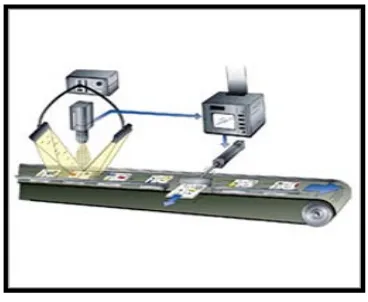
Since there is a wide range of technologies used in machine vision systems, the way they work also varies depending on the type of technology. At the most basic level, a camera or other image-capturing device monitors, records and reacts to a preset template of conditions given via a computer program. When the items that pass before the capture device deviate from the template and the preset measurements are recognized, the system or user is notified of the discrepancy. This is a key quality control feature in machine vision systems. Other machine vision systems are mostly used for visualization and image capture, which records a two dimensional image of an item within itself for later three dimensional virtual compositing. A typical machine vision system will consist of several among the following components:
1. One or more digital or analog camera (black-and-white or color) with suitable optics for acquiring images
2. Camera interface for digitizing images (widely known as a "frame grabber") 3. A processor (often a PC or embedded processor, such as a DSP)
4. (In some cases, the entire above are combined within a single device, called a smart camera).
5. Input/output hardware (e.g. digital I/O) or communication links (e.g. network connection or RS-232) to report results
6. Lenses to focus the desired field of view onto the image sensor.
7. Suitable, often very specialized, light sources (LED illuminators, fluorescent or halogen lamps etc.)
8. Program to process images and detect relevant features.
9. A synchronizing sensor for part detection (often an optical or magnetic sensor) to trigger image acquisition and processing.
6
Figure 2.1: Machine vision systems
2.3 The Advantages of MATLAB
MATLAB is a general purpose programming language. When it is used to process images one generally writes function files, or script files to perform the operations. These files form a formal record of the processing used and ensures that the final results can be tested and replicated by others should the need arise. MATLAB allows its users to accurately solve problems, produce graphics easily and produce code efficiently [18].
MATLAB provides many functions for image processing and other tasks. Most of these functions are written in the MATLAB language and are publicly readable as plain text files. Thus the implementation details of these functions are accessible and open to scrutiny. The defense can examine the processing used in complete detail, and any challenges raised can be responded to in an informed way by the prosecution [18].
7
MATLAB is a scientific programming language and provides strong mathematical and numerical support for the implementation of advanced algorithms. It is for this reason that MATLAB is widely used by the image processing and computer vision community. New algorithms are very likely to be implemented first in MATLAB; indeed they may only be available in MATLAB [18].
2.4 Image Processing
Image processing generally involves extraction of useful information from an image. This very useful information may be the dimensions of an engineering component, size of diagnosed tumor, or even a 3D view of an unborn baby. In Pakistan the main areas of application of image processing are bio-medical, engineering and quality control [15].
2.4.1 Image Processing in Matlab
8
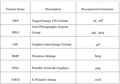
Format Name Description Recognized Extensions
TIFF Tagged Image File Format .tif, .tiff
JPEG
Joint Photographic Experts
Group .jpg, .jpeg
GIF Graphics Interchange Format .gif
BMP Windows Bitmap .bmp
PNG Portable Network Graphics .png
[image:21.612.126.528.63.344.2]XWD X Window Dump .xwd
Table 2.1: The image or graphics format
2.4.1.1 Image Conversion
9
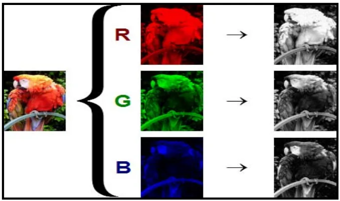
[image:22.612.165.506.136.338.2]I = rgb2gray(RGB) converts the truecolor image RGB to the grayscale intensity image I. rgb2gray converts RGB images to grayscale by eliminating the hue and saturation information while retaining the luminance [14].
Figure 2.2: RGB image to gray scale image
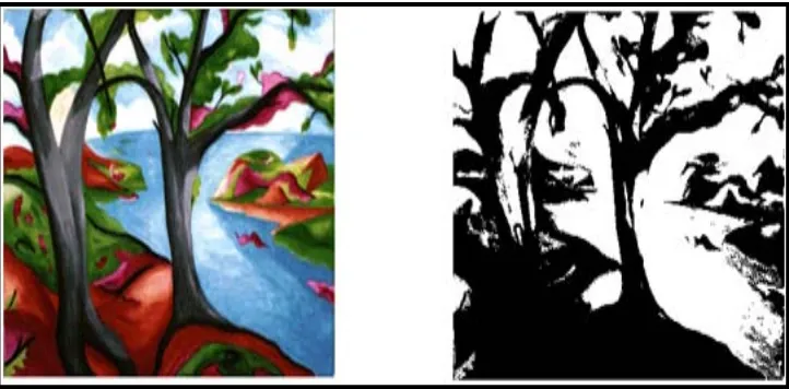
2.4.1.2 Thresholding
10
Categorizing Thresholding Methods are:
histogram shape based methods, where, for example, the peaks, valleys and
curvatures of the smoothed histogram are analyzed
Clustering based methods, where the gray-level samples are clustered in two
parts as background and foreground (object), or alternately are modeled as a mixture of two Gaussians
Entropy based methods result in algorithms that use the entropy of the
foreground and background regions, the cross-entropy between the original and binarized image, etc.
Object attribute-based methods search a measure of similarity between the
gray-level and the binaries images, such as fuzzy shape similarity, edge coincidence, etc.
[...] spatial methods [that] use higher-order probability distribution and/or
correlation between pixels
Local methods adapt the threshold value on each pixel to the local image
[image:23.612.154.515.407.585.2]characteristics."
11
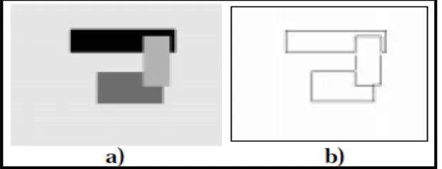
2.4.1.3 Edge Detection
Edges are considered to be most important image attributes that provide valuable information for human image perception. With the advent of artificial intelligence systems and forensic science the process of edge detection has achieved the most sought status. Edge detection is a very complex process affected by deterioration due to different level of noise. A number of operators are defined to solve the problem of edge detection. [1–6].
In early processes, the edge detection was mainly performed on software due to its large hardware requirement and also the application-specific integrated circuits have not gain much advancement. But present researches on programmable devices make it possible to implement edge detection algorithms on these devices whose design turn-around time varies from few hours to few days.[10]
Edge detection is the process of locating the edge pixels. Then an edge enhancement will increase the contrast between the edges and the background in such a way that edges become more visible [9]. Edge supports six different edge-finding methods which is Sobel, Prewitt, Roberts, Laplacian of Gaussian, Zero-cross and Canny method [2]. This edge function looks for places in the image where the intensity changes rapidly, using one of these two criteria:
Places where the first derivative of the intensity is larger in magnitude than
some threshold.
[image:24.612.152.462.567.686.2] Places where the second derivative of the intensity has a zero crossing. Example: