MOBILE ROBOT MULTIPLE SENSOR BEHAVIOUR FOR OBSTACLE AVOIDANCE
Abdul Razak bin Abdul Rahman
Bechelor of Electrical Engineering (Power Industry)
i
“ I hereby declare that I have read through this report entitle “Mobile Robot Multiple Sensor Behavior for Obstacle Avoidance” and found that it has comply the partial fulfillment for awarding the degree of Bachelor of Electrical Engineering (Industrial Power)”
ii
MOBILE ROBOT MULTIPLE SENSOR BEHAVIOR FOR OBSTACLE AVOIDANCE
ABDUL RAZAK BIN ABDUL RAHMAN
A report submitted in partial fulfillment of the requirements for the degree of Electrical Engineering (Industrial Power)
Faculty of Electrical Engineering
UNIVERSITI TEKNIKAL MALAYSIA MELAKA
iii
I declare that this report entitle “Mobile Robot Multiple Sensor Behavior for Obstacle Avoidance” is the result of my own research except as cited in the references. The report has not been accepted for any degree and is not concurrently submitted in candidature of any other degree.
Signature : ………
Name : ………
iv
ACKNOWLEDGMENT
Assalamualikum Warahmatullah Wabarakatuh.
Praise to Allah s.w.t, The All Mighty that give me the strength to finish and complete this report on time. Praise to Allah s.w.t for without His blessing this report would not have been completed.First of all would like to thank my parents who had been helping, motivating, and supporting me from the very beginning to the end in order to complete final project.
I also would like to thanks University Technical Malaysia, Melaka especially the Electrical Engineering faculty, for giving me the chance to be creative and innovation in our electrical component. With this opportunities, it’s give me more understanding with our electrical concept and learn how’s to thinking and build something new equipment that can give easier than before.
v
ABSTRACT
vi
ABSTRAK
vii
TABLE OF CONTENTS
CHAPTER TITLE PAGE
ACKNOWLEDGEMENT iv
ABSTRACT v
TABLE OF CONTENTS vii
LIST OF TABLES x
LIST OF FIGURES xi
LIST OF APPENDICES xiii
1 INTRODUCTION 1
1.1 Background 1
1.2 Problem statement 1
1.3 Objectives 3
1.4 Scope 3
2 LITERATURE REVIEW. 4
2.1 Mobile Robot 4
2.2 Sensor 7
2.2.1 Ultrasonic sensor 7
2.2.2 Infrared sensor 8
2.3 Microcontroller 10
2.4 Mobile Robot Design for This Project 11
3 RESEARCH METHADOLOGY. 12
viii
4 PROJECT DEVELOPMENT 20
4.1 Hardware development 20
4.1.1 Mobile robot structure 20
4.1.2 Shaft design 21
4.2 Electrical development 23
4.2.1 Relay circuit 23
4.2.2 Relay circuit operation 23 4.2.3 Limit switch operation 25 4.2.4 Sensor operation 26
4.3 Software development 27
4.3.1 CCS C compiler. 27
4.3.2 Proteus software 30
4.3.3 Import Hex file 30
5 RESULT ANALYSIS 32
5.1 Without sensor analysis 32 5.1.1 Forward and backward movement 32
5.1.2 Data analysis 34
5.1.3 Three hundred and sixty 35 degree (360⁰) rotation
5.1.4 Data analysis. 37 5.1.5 Ninety degree (90⁰) turns 38 5.2 Number eight formation analysis. 41
5. 2.1 Complete task 42
5.2.2 Data analysis 43
5.3 Sensor analysis 44
5.3.1 Analysis process. 46
5.3.2 Data Analysis 47
ix
6 DISCUSSION AND CONCLUSION. 49
6.1 Conclusion. 49
6.2 Recommendation 49
REFERENCES 50
APPENDICES 52
x
LIST OF TABLES
TABLE TITLE PAGE
5.1 Analysis result and data taken for forward 32 and backward movement
5.2 Analysis result and data taken for rotation on 35 clockwise and anti clockwise.
5.3 Analysis result and data taken for mobile robot turn. 39 5.4 Analysis result and data taken for mobile robot 42 complete the task.
xi
LIST OF FIGURES
FIGURE TITLE PAGE
Figure 1.1 Mobile robot application. 2
Figure 2.1 Example of Mobile Robot design. 4
Figure 2.2 Omni wheel application. 5
Figure 2.3 Omni wheel design 5
Figure 2.4 Mobile robot structures. 6
Figure 2.5 Ultrasonic sensor design. 8
Figure 2.6 The IR sensors with its cover. 9
Figure 2.7 Mobile robot designs with microcontroller. 11
Figure 3.1 Research Methodology. 14
Figure 3.2 Mechanical hardware construction. 15
Figure 3.3 Electrical hardware construction. 16
Figure 3.4 Software development. 18
Figure 3.5 ADC simulation test on Proteus. 19
Figure 3.6 Relay control simulation tested on Proteus. 19
Figure 4.1 Mobile robot structures. 21
Figure 4.2 Draft design of shaft. 21
Figure 4.3 Complete shafts. 22
Figure 4.4 Shaft connected with motor. 22
Figure 4.5 Relay circuit diagram. 24
Figure 4.6 Relay circuit. 24
Figure 4.7 Bumper with limit switch. 25
Figure 4.8 Ultrasonic sensors. 26
[image:12.612.108.497.143.725.2]Figure 4.9 New wizards on CCS C compiler and named the file. 27
Figure 4.10 PIC’s setting. 28
Figure 4.11 Analog to digital (ADC) setting. 28
xii
Figure 4.13 Circuit constructs using Proteus software. 30 Figure 4.14 Import hex file the simulation testing. 31 Figure 5.1 Comparison between forward and backward data. 33 Figure 5.2 Time (sec) and data taken to complete the rotation on clockwise. 36
andanticlockwise.
Figure 5.3 Mobile robot turn. 38
xiii
LIST OF APPENDICES
APPENDIX TITLE PAGE
A Planning schedule. 52
1
CHAPTER 1
INTRODUCTION
1.1 Background
Mobile Robot can be classified into a few types based on the application and task given to complete. Mobile robot with multiple sensor behavior for obstacle avoidance is one of the autonomous mobile robot types. This robot can perform the tasks without any guidance from human and but limited to environment structured [1]. In the autonomous mobile robot designed, the most important is the position of the sensor attached to the robot. These sensors are act as an eye for alls mobile robot designed where it was used to decide the direction of the wheel and based on the task given.
However, autonomous mobile robot cannot operate smoothly with sensor only. It should have a controller that act as a heart where the controller will control the whole operation of the mobile robot based on program installed [2].Basically, positioning of sensor is the most difficult part in autonomous mobile robot designed depends on sensors’ specifications and the sight where needs to give strictly attentions. If the research of the sensor ranges is studied, determination of the movement on left or right will totally affect to the whole operation of mobile robot [3].
1.2 Problem statement
The m own d differe and im robot i sensor be pla surrou object avoid is base planni efficie mobile robot dimensions. ent environm mmobile obs
in the real lif
What impo r uses and it ace in a bet unding and e
ts and obstac collapsed. In ed on surrou ing level [5] ency.
also can tran Nowadays, ment that are stacles [4]. F
fe.
Fig
ortant of sen ts’ position i tter location
environment cles and this
n navigation unding infor ]. Else too m
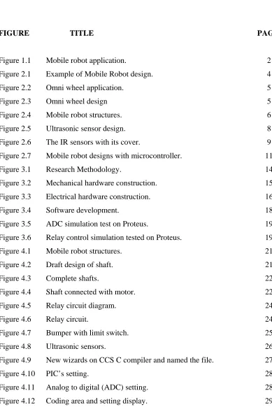
nsport mater mobile rob e often clutt Figure 1.1 sh
gure 1.1: Mo
nsors and se in mobile ro where the t needs to a s is the most n and in unk rmation proc
many senso
rial or tools bot have bee
tered with l hows ones o
obile robot ap
ensors’ locat obot designs
range of se analyses by t important s known terrain cessing is us rs used will
over distanc en assigned ots of know of the most a
pplication.
tion in robo is the majo ense can be
measure th source inform n exploration sed common l increase th
ces much lar d to work in wn and unkn applications
ot design? T or problem. S
fully utiliz e robot dist mation that n, the kind o nly in roboti he designed
rger than the n a certain nown, movin
of the mobi
he number Sensor shou ed. A robot tance to oth must know of control th ics at the tas
[image:16.612.213.408.187.424.2]3
1.3 Objectives
This project was design based on the following objectives, which are:
1. To design a mobile robot that can avoid the obstacle.
2. To use a microcontroller as a main controller to control the movement of the robot.
1.4 Scope
In order to complete this project, the process is divided into few scopes as follows:
1. The work involves in this project is to design and to fabricate the mechanical and electronic hardware for a prototype of mobile robot. This task includes the design of robot structure/base, microcontroller and sensors circuit.
2. To study the sensor behavior and create an algorithm for the movement of mobile robot in applying the sensor behavior.
4
CHAPTER 2
LITERATURE REVIEW.
2.1 Mobile Robot
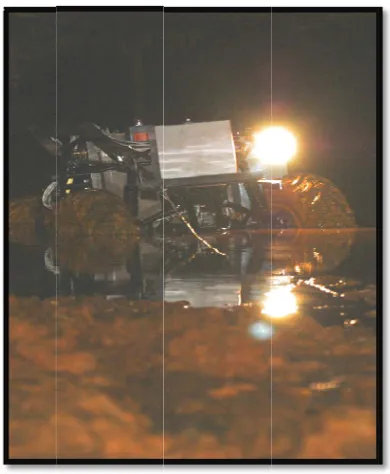
[image:18.612.164.463.448.586.2]Mobile robot design is about art and individual skill to create the useful robot for human application. Each part of mechanical, electrical and software should be studies to make sure that the alls mobile robot application can run smoothly and can complete the task given. In mechanical part, each measurement of the mobile robot design must be details and fixed to make sure that the cost is not changes and affect to the whole process design. In electrical and software part also need research because the price is quite expensive and more sensitive if compare with the mechanical. Each equipment specification must be study details from it design, application and until the prices [9]. Figure 2.1 shows the example of mobile robot design with the range covered by sensor.
5
Van-Quyet Nguyen et al studies about obstacle avoidance of mobile robot where is include about the design and the operation. On hardware design, they used the control software, out-case covers, aluminum beams and plastic connectors, scooter wheels, two stepper motors, and a power module, a battery (12V, 7A). On his paper stated that the design is most suitable on the application of their mobile robot. [1].
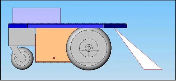
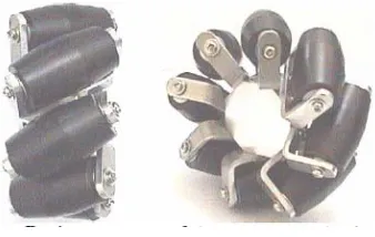
[image:19.612.249.383.347.460.2]Jefri Efendi Mohd Salih et al.studies the designed of Omni-Directional Mobile Robot with Mecanum Wheel. They state that each of individual wheel direction and speed can be combined and will produces the bizarre results where is can allowed the freely movement in the direction without changing direction of the wheel [2]. Figure 2.2 shows the Omni wheel applied in mobile robot designed by Jefri Efendi Mohd Salih, which gives better turning either to right or left but robot movement a bit slower due to Omni wheel’s characteristic as shown in Figure 2.3.
Figure 2.2: Omni wheel application.
[image:19.612.228.397.536.643.2]6
[image:20.612.224.402.255.390.2]
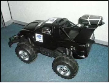
MHA Hamid, AH Adom, NA Rahim, MHF Rahiman in studies about navigation of mobile robot using global positioning system (GPS) and obstacle avoidance system with commanded loop daisy chaining application method mobile robot for experiment utilized the use of remote control (RC) truck with the dimension of 50 cm in length, 25 cm in width and 15 cm in height. The RC truck include with four independent motor that can actuated individually which can skid steer to turn the mobile robot in immediate 360 degree turn. Equipped with seal lead acid battery, mobile robot increases the capability to move in longer time. Figure 2.4 show mobile robot structures integrated with GPS and sonar sensor [3].
Figure 2.4: Mobile robot structures.
Meng Joo Er and Chang Deng studies about obstacle avoidance of a mobile robot using hybrid learning stated that the Khepera robot used is cylindrical in shape, measuring 55 mm in diameter and 30 mm in height. Its weight is only 70 g. They also state that the small size allows experiments to be performed in a small work area [4].
7
2.2 Sensor
2.2.1 Ultrasonic sensor
William et al. had studies about implementation of a binaural sensory pod using an ultrasonic emitter and two receivers on a legged robot. A series of obstacle avoidance behavior is programmed onto a microcontroller that allows the robot to move both semi-autonomously and semi-autonomously successfully programmed. From his studies, binaural ultrasonic sensor pod and programmed avoidance behavior has proven itself useful as a mobile robot navigation aid. By using the modular design implemented for these experiments, the sensor pods could be integrated with other mobile robots to provide non-contact sensing and navigation for them as well. [6].
J. Borenstein et al.on their paper about Mobile Robot Positioning & Sensors and Techniques had briefly described and defined that the seven categories for positioning systems where are Odometry, Inertial Navigation, Magnetic Compasses, Active Beacons, Global Positioning Systems, Landmark Navigation, and Model Matching. Each categories had their own characteristic and specialize like can make measurement of distance by the position, radius, x and y axis and more characteristic. [7].
8
[image:22.612.195.444.114.182.2]
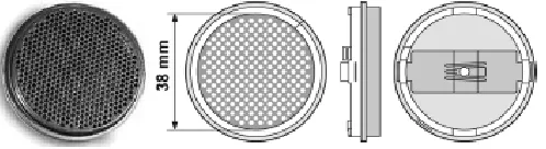
Figure 2.5: Ultrasonic sensor design.
2.2.2 Infrared sensor
Shadia Elgazzar and Timothy Welch stated that the sonar sensor can act and working as ultrasonic sensor application. It also can determine the distance between the sensors and object sharply and it also more cheaper compared to the ultrasonic sensor. Even it was cheaper and can operate similarly like an ultrasonic sensor, but the range coverage of infrared sensor only can reach until 3meters maximum compare with ultrasonic where can reach until 6 meters. This showed that the infrared are most suitable in the small application of mobile robot than using ultrasonic sensor [9].
9
Jose Vazquezand Chris Malcolm in their studies mention that the maximum range of the infrared sensor is three meters with the beam width 450. The laser ranging is usually not used because the price is most expensive compared to infrared. In the research, the extract features from sonar sensors based on triangulation plus infrared sensing have been implemented successfully [11].
Heon-Hui Kim Yun-Su Ha Gang-Gyoo Jin on a studies about the Environmental Map Building for a Mobile Robot Using Infrared Range-finder Sensors stated that the sensor adopted for this work is infrared range-finder PB9-01 manufactured by HOKUYO AUTOMATIC, which uses an infrared LED modulated at 87ohm for signal generation. It not only has compact size and light weight but also gets distant and directional information to an object for one time scanning [12].
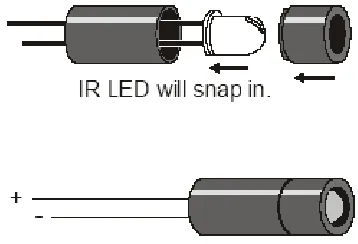
[image:23.612.230.409.471.593.2]Matijevics studied about Infrared Sensors Microcontroller Interface System for Mobile Robots stated that the IR sensor consists IR LED emitter and photo sensitive transistor Photo-transistor is in a plastic house with filter for daylight. LED is in series connection with resistor and controlled over the microcontroller out pin. There are two IR sensors in front of robot. The IR sensor is used with 980 nm wavelength light [13]. Figure 2.6 shows the IR sensor with its cover.
10
2.3 Microcontroller
MHA Hamid et al. studied about Navigation of Mobile Robot Using Global Positioning System (GPS) and Obstacle Avoidance System with Commanded Loop Daisy Chaining Application Method stated the mobile robot for their project is suitable used micro controller in Basic stamp BS2 and BS2p. For BS2 it offer processor speed 20 MHz and it can execute approximately 4000 instruction per second. RAM size for BS2 is 32 bytes and 2K bytes memory for EEPROM about 500 instructions can be store in flash memory [13].
Chan Zhi Wei and Muhammad Nasiruddin Mahyuddin studied about Neuro-Fuzzy Algorithm for Obstacle Avoidance Mission of a Mobile Robot Using FPGA discussed that the designed obstacle avoidance program for mobile robot that incorporates a neuro-fuzzy algorithm using Altera Field Programmable Gate Array (FPGA) development board. Field Programmable Gate Array (FPGA) circuits provide suitable platform in realizing complex hardware system as well as implementing data intensive algorithm computation. The ability to easily reconfigure FPGA makes the design less expensive than pre-designed hardware. These features bring convenience to incorporating an artificial intelligence-based-program for mobile robot navigation and obstacle avoidance task or mission [3].