This is a repository copy of
The effect of grading the atomic number at resistive guide
element interface on magnetic collimation
.
White Rose Research Online URL for this paper:
http://eprints.whiterose.ac.uk/103720/
Version: Published Version
Article:
Alraddadi, R. A B, Robinson, A. P L, Woolsey, N. C. orcid.org/0000-0002-2444-9027 et al.
(1 more author) (2016) The effect of grading the atomic number at resistive guide element
interface on magnetic collimation. Physics of Plasmas. 072706. ISSN 1089-7674
https://doi.org/10.1063/1.4959037
[email protected] https://eprints.whiterose.ac.uk/ Reuse
Items deposited in White Rose Research Online are protected by copyright, with all rights reserved unless indicated otherwise. They may be downloaded and/or printed for private study, or other acts as permitted by national copyright laws. The publisher or other rights holders may allow further reproduction and re-use of the full text version. This is indicated by the licence information on the White Rose Research Online record for the item.
Takedown
If you consider content in White Rose Research Online to be in breach of UK law, please notify us by
The effect of grading the atomic number at resistive guide element interface on
magnetic collimation
R. A. B. Alraddadi, A. P. L. Robinson, N. C. Woolsey, and J. Pasley
Citation: Physics of Plasmas 23, 072706 (2016); doi: 10.1063/1.4959037 View online: http://dx.doi.org/10.1063/1.4959037
View Table of Contents: http://scitation.aip.org/content/aip/journal/pop/23/7?ver=pdfcov Published by the AIP Publishing
Articles you may be interested in
Response of microscale turbulence and transport to the evolution of resistive magnetohydrodynamic magnetic island
Phys. Plasmas 21, 020703 (2014); 10.1063/1.4865378
Simulations investigating the effect of a deuterium-tritium-ice coating on the motion of the gold cone surface in a re-entrant cone-guided fast ignition inertial confinement fusion capsule
Phys. Plasmas 14, 054501 (2007); 10.1063/1.2734584
The effect of safety factor and magnetic shear on turbulent transport in nonlinear gyrokinetic simulations Phys. Plasmas 13, 022305 (2006); 10.1063/1.2169804
Charge separation effects in magnetized electron ion plasma expansion into a vacuum Phys. Plasmas 10, 4559 (2003); 10.1063/1.1611882
The effect of grading the atomic number at resistive guide element interface
on magnetic collimation
R. A. B.Alraddadi,1A. P. L.Robinson,2N. C.Woolsey,1and J.Pasley1,2
1York Plasma Institute, University of York, York YO10 5DD, United Kingdom
2Central Laser Facility, STFC Rutherford-Appleton Laboratory, Didcot OX11 0QX, United Kingdom
(Received 23 March 2016; accepted 5 July 2016; published online 21 July 2016)
Using 3 dimensional numerical simulations, this paper shows that grading the atomic number and thus the resistivity at the interface between an embedded high atomic number guide element and a lower atomic number substrate enhances the growth of a resistive magnetic field. This can lead to a large integrated magnetic flux density, which is fundamental to confining higher energy fast electrons. This results in significant improvements in both magnetic collimation and fast-electron-temperature uniformity across the guiding. The graded interface target provides a method for resistive guiding that is tolerant to laser pointing.Published by AIP Publishing.
[http://dx.doi.org/10.1063/1.4959037]
I. INTRODUCTION
Plasma resistivity induces a significant magnetic field inside an overdense plasma when a shear in the fast electron current density or resistivity gradient exists. This is described by the induction equation in the hybrid approximation1
@ ~B
@t ¼g r ~jf
þ rð gÞ ~jf; (1)
whereB~is the flux density of the magnetic field,gis the re-sistivity, and~jf is the fast electron current density. The first term on the right-hand side generates a magnetic field that directs electrons towards regions of higher current density, and thus, acts to collimate the fast electron beam. The second term, which forms the basis of the resistive guiding con-cept,2,3 generates a magnetic field at resistivity gradients which acts to keep the fast electrons within regions of higher resistivity. The resistivity gradient is created by a transition between two materials with different atomic number Z. This can be in the form of high-Z solid wire (the guide) embedded in a lower-Z substrate.4 The resistivity gradient is in the transverse direction to that of the fast electron beam propaga-tion. The fast electrons are generated within the guide, and the magnetic field at the interface between this guide and the substrate (of lower Z material) will deflect the electrons and keep them inside the high-Z material.
The ability of a resistive guide to confine fast electrons depends on the ratio of the fast electron Larmor radius to the generated azimuthal magnetic field width L/. The confine-ment condition of the fast electrons along the guide is expressed as2,5
B/L/Pf
e ð1coshdÞ; (2)
where B/ is the azimuthal magnetic flux density, Pf ¼
cfvfme is the fast electron momentum,cf is the Lorentz
fac-tor,vfis the fast electron velocity, andhdis the fast electron
divergence angle. This implies that the product of B/L/ needs to be larger than the fast electron momentum to reflect
the fast electrons back towards the guide axis.2,4 For fast electrons entering the guide at an angle ofhd¼30 with an
energy of 1.8 MeV, aB/L/ of 103Tm is needed for con-finement. The product ofB/L/ needs to be larger than this when either the entrance angle or the fast electron energy increases. For example,B/L/has to be about7103Tm for 4.5 MeV fast electrons with an angle ofhd¼50.
The resistive guide has been suggested for applications such as the Fast Ignition approach to the inertial confinement fusion scheme6,7where the energetic fast electrons need to be guided through an overdense stand-off distance of 100lm or more8 and deposited into the compressed core of deuterium-tritium (DT) plasma. It has been suggested that a resistive guide element can also be used as a driver in hydro-dynamic experiments4,9 since strong heating occurs where the fast electron beam is collimated. Robinson et al.4 have investigated analytically and numerically the most significant parameters that affect the heating of the resistive guide ele-ment. They find that, for example, the ratio of the guide radi-us to the laser spot radiradi-us needs to be comparable in order to obtain good heating. In a real laser system, this condition is difficult to achieve due to the limitation of the laser pointing stability. If the laser hits the edge of the resistive guide ele-ment rather than its centre, the guide will not achieve its aim as a collimator and the fast electrons will couple into the sub-strate. Therefore, a larger radius guide is needed. However, numerical work4,9shows that by using a larger radius guide, magnetic fields develop within the guide close to its axis degrading heating uniformity. These “interior” magnetic fields are due to inhomogeneous propagation of the fast elec-trons.10 They produce an annular transport pattern which leads to preferential heating of the outer regions of the guide. Hitherto, the resistive guide in all previous experimen-tal11,12 and numerical4,9studies, has an engineered step-like atomic number interface between the guide and the substrate regardless of the guide geometry. We will refer to this con-figuration as “step-like” resistive guide concon-figuration. Since the resistive magnetic field is produced at the guide-substrate interface, changing the interface resistivity away from a
1070-664X/2016/23(7)/072706/6/$30.00 23, 072706-1 Published by AIP Publishing.
step-like interface offers a means to improve electron guid-ing and enable heatguid-ing of a larger radius guide. We find that grading the atomic number across a layer at the guide-substrate interface (so that the atomic number, and thus the re-sistivity, decreases with increasing radius) enhances the growth of resistive magnetic field. This cladding layer can lead to a larger integrated magnetic flux density, which improves the magnetic collimation of the fast electrons. Furthermore, as a result of this, simulations show an improve-ment in radial heating uniformity in the larger radius guide.
This paper is structured as follows; Sec.IIcontains a de-scription of the different resistive guide designs. Sec.III out-lines the simulation set up and the simulation results and discussion are contained in Secs.IVandV, respectively.
II. GRADING THE ATOMIC NUMBER AT THE INTERFACE OF THE GUIDE ELEMENT
To highlight the impact of a graded-interface, four simu-lations are reported. Two use a step-like interface (simula-tions A and B in Table I) and two use a shaped or graded interface (C and D in TableI). The aim of these simulations is to compare the resulting magnetic collimation and radial temperature profiles in the guides. The guide is a cylindrical wire in all simulations as summarised in TableI.rguideis the
total radius of the embedded guide whereasrcoreis the radius
of the core of the guide. The core has not been graded. vis the ratio of the radius of the corercoreto the laser radius spot
rspot. It was found that for graded-interface targets, this ratio
needs to be less than 1. Whenv>1, the fast electron beam breaks into filaments inside the guide resulting in non-uniform radial heating of the guide.
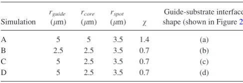
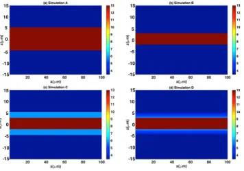
Figures1(a)–1(d)show 2-dimension z-x plane slices of the target Z profile for targets A to D. These figures are taken in the midy-direction at15<z<15 along thex-direction. The materials used in simulations A and B are solid density (2.7 g cm3) aluminium guide (Z¼13) embedded into a sol-id (1.0 g cm3) CH plastic (Z¼3.5) substrate. The differ-ence between simulations A and B is the guide radius, which is 5lm and 2.5lm, respectively. The resistive guide design in simulation C (Figure1(c)) is an Al guide clad in a carbon (density 2.2 g cm3) layer. This resembles a co-axial cable design. We refer to this design as “co-axial” resistive guide, and the overall radius of this co-axial guide is 5lm. Simulation D, Figure1(d), uses an Al guide of radius 2.5lm clad in a graded layer of material of linearly decreasing Z from Z¼6 to Z¼3.5 between radial positions of 2.5lm and 5lm. The overall radius of the guide (with cladding) is 5lm. This is embedded in a CH plastic substrate. The radial atomic number profiles are shown in Figures2(a)–2(d). The
fast electrons are injected into the guide from the left hand side atx¼0 and the centre ofyandz.
III. SIMULATION SET UP
The simulations were performed using the 3 dimensional particle hybrid code ZEPHYORS,4,13 which is based on the hybrid method developed by Davies in a series of publica-tions.13,14 ZEPHYORS is used to simulate the 3D relativistic motion of electrons under the influence of self-generated resis-tive electric and magnetic fields, as well as collisions. The fast electron current~jf propagates into the plasma when it is spa-tially coincident and nearly balanced with cold return electron current~jr that is drawn from the background,15i.e.,~jf ~jr. The resistive electric field is estimated from Ohm’s law, E¼ g~jf, with displacement current dropped from the Ampere law. Ignoring displacement current relies on the as-sumption that the change in the electric field with time is slow. This is valid since the width of the beam, i.e., the fast electron bunch radius, is much smaller than the length of the fast elec-tron bunch. In addition, the elecelec-tron pressure term (rPe/ne)
is also neglected in Ohm’s law. The reason for this is that the contribution of the electric field from this term is small by about two orders of magnitude compared to the electric field obtained from the resistive term. Thus, from Faraday’s law, the resulting resistive magnetic field arising due to the fast electrons can be written as Eq.(1). The return electron current heats the background plasma, via Ohmic heating, with power density~jr:Egj2f. The background electrons are treated as a static fluid that experience heating, ionization, and change in resistivity. The static treatment of the background is reasonable as the hydrodynamic displacement is about 0.1lm in 1 ps for targets heated to 100 eV, assuming that the sound speed is 105m/s. The Thomas-Fermi model is used to obtain the ionisa-tion and specific heat capacity of the background. The resistiv-ity is temperature dependent and based on that of Lee and More resistivity model.16The temperature is calculated by the energy deposition due to the slowing down of the fast electrons and the Ohmic heating induced by the return electron current. The fast electron population is described kinetically using the Vlasov equation, which is solved via the particle-in-cell (PIC) method. Collisions are included using the Fokker-Planck colli-sional operators, which account for angular fast electron scat-tering from background ions and electrons, together with drag generated by the background electrons. The mathematical expressions of the collisional operators are obtained from Davies13equations(1)and(2). More details about the physics of hybrid code can be found in the study by Robinsonet al.8
A 200100100 grid was used with a 0.5lm cell size in each direction. The number of macroparticles injected into each of the cells was 126. This helped to reduce statistical noise. The target, as described above, consisted of a CH plastic substrate within which a guide of radiusrguidewas embedded.
[image:4.607.48.292.71.154.2]This guide is co-linear along thex-axis and centred onyandz as shown in Figure 1. The laser irradiation intensity was 1.271020W cm2with a pulse duration of 2 ps and the laser wavelength of 1lm. It is assumed that 30% of the laser energy was coupled to the fast electrons. The temporal profile of the fast electron beam is top-hat shaped and the transverse profile
TABLE I. Table of guide geometric parameters.
Simulation
rguide (lm)
rcore (lm)
rspot (lm) v
Guide-substrate interface shape (shown in Figure2)
A 5 5 3.5 1.4 (a)
B 2.5 2.5 3.5 0.7 (b)
C 5 2.5 3.5 0.7 (c)
D 5 2.5 3.5 0.7 (d)
is / exp½ r2 2r2
spot, where rspot¼3.5lm. The choice of rspot¼3.5lm was to ensure that the electron beam source is
within the resistive guide of 5lm. It is worth mentioning that these choices of small sizes of bothrspotandrguidewere to
min-imise the simulation time. The fast electron angular distribution is uniform over a solid angle and defined by the half-angle of divergence 50. The energy distribution of the fast electrons is from the reduced Wilks’ ponderomotive scaling,17 giving Tf¼2.7 MeV.18The resistivity uses the Lee and More model
and a minimum mean free path as 5rs, wherers is the
inter-atomic spacing. From TableI, it can be seen that simulations
A, C, and D have totalrguide>rspotensuring that the electron
beam source is within the guide. This is not the case in simula-tion B where rguide<rspot. However, rcore in simulation B is
identical to that in simulations C and D.
IV. RESULTS
A. The effect of design on the azimuthal magnetic field rate
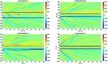
Figures 3(a)–3(d) show an x-z slice taken at the mid-plane of y of the generated magnetic field at 2.2 ps for
FIG. 1. (a)–(d) show the target Z pro-file for simulations A to D, respective-ly. Simulations A and B use a step-like interface and the difference between the two is only in the guide radius. Simulation C uses a shaped interface resembling a co-axial cable design. Simulation D uses the graded interface resistivity cladding guide.
FIG. 2. (a)–(d) show the radial atomic number profile for simulations A to D, respectively. Simulations A and B use Aluminium guide. Simulation C uses an Al guide clad in a carbon layer. Simulation D uses an Al guide clad in a graded layer of the material of linearly decreasing Z. All the guides are embedded into the CH plastic substrate.
[image:5.607.52.409.57.307.2]simulations A to D. Generally, an azimuthal magnetic field has been generated at the interface between the guide and the CH plastic substrate. This field provides collimation for the fast electrons. Radial expansion of the fast electron beam is evident from the formation of the magnetic field in the CH plastic substrate outside the guide. In simulation A (Figure 3(a)), magnetic field features are evident within the guide, and these are close to the axis and are most noticeable occur-ring betweenx¼20lm andx¼40lm. Here, therguide>rspot
andvis larger than 1. This “interior” magnetic field is due to the inhomogeneous propagation of the fast electrons.10 The generation of these fields within the guide is undesirable and inhibits radially uniform fast electron heating.
Magnetic fields interior to the guide are not observed in simulations B, C, and D wherev<1 althoughrguide>rspotin
simulations C and D. This implies that more uniformity of the fast electron propagation is obtained in these guides. In simu-lation C, the co-axial resistive guide, two azimuthal magnetic fields are observed, the first is between the guide and the CH plastic substrate at radial positions of 5lm and the second is between the carbon cladding and the aluminium core, i.e., at radial position of 2.5lm. Because of this, the fast electrons are confined at three individual positions, between5lm and
2.5lm,2.5lm andþ2.5lm, andþ2.5lm andþ5lm as shown in Figure3(c). The azimuthal magnetic fields in simu-lations B and D shown in Figures3(b)and3(d), respectively, are similar although the total guide radius in simulation D is twice that in simulation B. In simulation D, the azimuthal magnetic field is generated along the graded region of the guide and located along the interface with the core of the guide. The observation that the magnetic flux density in simu-lation D is higher than that in simusimu-lation B, which has a step-like interface, by 103T is notable and important. Simulation D also indicates that changing the interface shape does not sig-nificantly affect the width of the magnetic field.
Figure4shows the resulting productB/L/as a function of time which is extracted at x¼10lm, and in the y mid-plane for all the simulations. The productB/L/is calculated from the peak of the magnetic field and the FWHM. Simulation D has the largest productB/L/of all simulations and indicates that this guide can confine higher energy elec-trons. A high value ofB/L/(103Tm at 200 fs in simulation D) is important to collimation of the fast electron beam and subsequent heating of the guide. Simulation B achieves a similar B/L/ by 300 fs; however, since rguide<rspot, more
[image:6.607.98.517.58.308.2]fast electrons escape the guide and move into the CH plastic substrate. This reduces theB/L/product further limiting the fast electron confinement. TheB/L/product in simulation C is inferior to that in simulation A as the fast electrons are confined in multiple regions of the guide as shown in Figure 3(c). Nevertheless, we find (see in Sec. IV B) that the radial heating within the guide in simulation C is more uniform
FIG. 3. x-z slice of the magnetic field (T) in theymidplane at 2.2 ps for simulations A to D.
FIG. 4. The product ofB/L/near the head of the beamx¼10lm at
differ-ent times in fs.
[image:6.607.316.556.565.735.2]than in simulation A. This is because electron beam filamen-tation is suppressed even in situation where a coaxial guide has higher current densities. In summary, a resistive guide using a graded interface increases the magnetic flux density and produces a significantly larger B/L/ product. This enhances electron confinement.
B. The effect of design on the guide heating
Figure5shows an x-zslice of the background tempera-ture in eV taken in the midy-plane at 2.2 ps for simulations A to D. Strong resistive return current heating occurs in the guides where the fast electrons are collimated. There is a gra-dient in temperature with depth along the guide (x-direction) which is observed in all simulations. However, this gradient differs in each simulation due to electron confinement which results from the differences in the generated azimuthal mag-netic field. Non-uniform radial heating is observed in simula-tion A with striking annular temperature profiles at x¼20lm andx¼40lm. This corresponds to the location of the interior magnetic field previously noted (see Figure3(a)). More uniform heating is obtained in simulation B; this is due to the small radius of the guide, and similar results are noted by Robinsonet al.4The heating in simulation B is compara-ble to simulation D which has twice the guide radius. This result is important and identifies a possible method for designing targets that are tolerant of laser pointing stability. The key is to increase the guide radius using a graded resis-tivity cladding. The laser pointing stability in this design will be subject of future work as we will closely examine this in
more detail. The resulting guide has good radial temperature uniformity and relatively unstructured decrease in tempera-ture along the depth. The resistivity grading between the guide core and plastic substrate with v<1 ensures that the fast electrons with diverging trajectories are redirected to-wards the higher resistivity regions. Temperatures in simula-tion C are lower and more structured than in simulasimula-tions B and D. This is expected based on the simulatedB/L/. The temperature in simulation C is higher than in simulation A although the B/L/ product is lower. This results from the lack of internal magnetic field in co-axial target design.
The cross-section from Figure 5is shown in Figure 6. These are taken at 2.2 ps along the guide depth at the centre ofyandzaxes. The effect of the internal magnetic field ex-cluding fast electrons and leading to poor heating at x¼20lm andx¼40lm in the centre of the guide in simula-tion A is evident. An important comparison is between simu-lations B, C, and D wherev<1. There is oscillation in their temperature profiles within 15lm of the surface. This is due to inhomogeneity in the fast electron propagation near the in-jection region. After this, a gradual reduction in the tempera-ture occurs. The differences in temperatempera-ture between simulations B and D is due to the fact that thatrguide>rspot
in simulation D whilerguide<rspotin simulation B.
[image:7.607.95.512.437.746.2]It is worth mentioning that the fast electrons heat the re-sistive guide structure to high temperatures in few picosec-onds. As discussed in Sec. III, the hydrodynamic motion becomes important on a timescale of 10–30 ps and it should be negligible at time up to 1–3 ps. It is expected that a strong hydrodynamic expansion of the guide and the thermal
FIG. 5.x-zslice of the background temperature (eV) in theymidplane at 2.2 ps for simulations A to D.
electron transport into the surrounding material will have significant role in the multi-picosecond timescale. In addi-tion, depending on the choice of different parameters, the strong heating of the resistive guide may potentially lead to the generation of strong shocks into the surrounding materi-al.4Our simulations only capture the dominant physics in the regime of interest of 1 to few ps timescales where the fast electron can heat the guide before any significant hydrody-namic motion occurs or thermal transport.
V. DISCUSSION AND CONCLUSION
In this paper, we have investigated the effect of chang-ing resistivity (by changchang-ing Z) on the claddchang-ing layer around the core of a fast electron guide. We find that a cladding lay-er leads to suplay-erior guiding of electrons than in structures with a step-like change in resistivity. We find that a linear gradation in Z enhances the growth of resistive magnetic field, leading to an improvement in the magnetic collimation. The product B/L/ becomes significantly larger with a graded-interface compared to step-like and co-axial resistive guides. The graded-interface configuration is beneficial for four reasons; it helps in collimating the fast electrons uni-formly in the core of the guide. Second, a larger guide radius is possible using the graded interface. This is more tolerant to the laser pointing stability. Third, an increase in theB/L/ product early in the electron injection into the guide pro-motes fast electron confinement. And last, it helps reduce in-terior magnetic fields. The condition for best performance of the graded interface resistivity cladding is when the ratio
between the core of the guide and the laser spot radius is less than 1.
The fabrication of the graded interface resistivity clad-ding guides is possible using the alloys. Our simulations sug-gest that improved heating uniformity afforded by a fast electron guide with a graded resistivity cladding is of consid-erable benefit. Although the fabrication processes are not easy task compared to the step-like resistive guide, the gains obtained from this type of design mean that the fabrication development effort will be worthwhile. The development in micro-scale target fabrication indicates that target fabricators will soon be able to manufacture such targets.
ACKNOWLEDGMENTS
The authors are grateful for the use of computing resources provided by STFC’s Scientific Computing Department and Central Laser Facility (CLF). R.A.B.A. would also like to thank the King Saud University, Saudi Arabia for Ph.D. funding. A.P.L.R. is grateful for support from the ERC via STRUCMAGFAST grant (ERC-STG-2012).
1A. Bell, J. Davies, and S. Guerin,Phys. Rev. E58, 2471 (1998). 2A. Robinson and M. Sherlock,Phys. Plasmas14, 083105 (2007). 3
A. Robinson, H. Schmitz, J. Green, C. Ridgers, and N. Booth,Plasma Phys. Control. Fusion57, 064004 (2015).
4A. Robinson, H. Schmitz, and J. Pasley,Phys. Plasmas20, 122701 (2013). 5A. Robinson, M. Sherlock, and P. Norreys,Phys. Rev. Lett.100, 025002
(2008). 6
M. Tabak, J. Hammer, M. E. Glinsky, W. L. Kruer, S. C. Wilks, J. Woodworth, E. M. Campbell, M. D. Perry, and R. J. Mason, Phys. Plasmas1, 1626 (1994).
7
M. Tabak, D. Clark, S. Hatchett, M. Key, B. Lasinski, R. Snavely, S. Wilks, R. Town, R. Stephens, E. Campbell et al., Phys. Plasmas 12, 057305 (2005).
8A. Robinson, D. Strozzi, J. Davies, L. Gremillet, J. Honrubia, T. Johzaki,
R. Kingham, M. Sherlock, and A. Solodov, Nucl. Fusion 54, 054003 (2014).
9A. Robinson, H. Schmitz, J. Green, C. Ridgers, N. Booth, and J. Pasley,
Phys. Plasmas22, 043118 (2015). 10
A. Robinson and H. Schmitz,Phys. Plasmas20, 062704 (2013). 11
S. Kar, A. Robinson, D. Carroll, O. Lundh, K. Markey, P. McKenna, P. Norreys, and M. Zepf,Phys. Rev. Lett.102, 055001 (2009).
12B. Ramakrishna, S. Kar, A. Robinson, D. Adams, K. Markey, M. Quinn,
X. Yuan, P. McKenna, K. Lancaster, J. Greenet al.,Phys. Rev. Lett.105, 135001 (2010).
13J. R. Davies,Phys. Rev. E65, 026407 (2002).
14J. Davies, A. Bell, M. Haines, and S. Guerin,Phys. Rev. E56, 7193 (1997). 15
A. R. Bell, J. R. Davies, S. Guerin, and H. Ruhl,Plasma Phys. Control. Fusion39, 653 (1997).
16Y. Lee and R. More,Phys. Fluids27, 1273 (1984).
17S. C. Wilks, W. L. Kruer, M. Tabak, and A. B. Langdon,Phys. Rev. Lett. 69, 1383 (1992).
18
[image:8.607.51.293.57.229.2]M. Sherlock,Phys. Plasmas16, 103101 (2009). FIG. 6. Line-out of the background temperature in eV at 2.2 ps in
simula-tions A to D alongx-direction at the centre ofyandz.