UNIVERSITI TEKNIKAL MALAYSIA MELAKA
DEVELOPMENT OF ELECTRONIC NOTICE BOARD USING
WIRELESS TECHNOLOGY
This report is submitted in accordance with the requirement of the Universiti Teknikal Malaysia Melaka (UTeM) for the Bachelor of Electronics Engineering
Technology (Telecommunications) with Honours.
by
MOHAMMAD SAIFULLAH BIN AMER B071310178
910223-10-5495
UNIVERSITI TEKNIKAL MALAYSIA MELAKA
BORANG PENGESAHAN STATUS LAPORAN PROJEK SARJANA MUDA
TAJUK: Development of Electronic Notice Board Using Wireless Technology
SESI PENGAJIAN: 2016/17 Semester 1
Saya MOHAMMAD SAIFULLAH BIN AMER
mengaku membenarkan Laporan PSM ini disimpan di Perpustakaan Universiti Teknikal Malaysia Melaka (UTeM) dengan syarat-syarat kegunaan seperti berikut:
1. Laporan PSM adalah hak milik Universiti Teknikal Malaysia Melaka dan penulis. 2. Perpustakaan Universiti Teknikal Malaysia Melaka dibenarkan membuat salinan
untuk tujuan pengajian sahaja dengan izin penulis.
3. Perpustakaan dibenarkan membuat salinan laporan PSM ini sebagai bahan pertukaran antara institusi pengajian tinggi.
4. **Sila tandakan ( )
SULIT
TERHAD
TIDAK TERHAD
(Mengandungi maklumat yang berdarjah keselamatan atau kepentingan Malaysia sebagaimana yang termaktub dalam AKTA RAHSIA RASMI 1972)
(Mengandungi maklumat TERHAD yang telah ditentukan oleh organisasi/badan di mana penyelidikan dijalankan)
Alamat Tetap:
Lot 4010 Batu 9 Jalan Kempas,
Kg Bukit Kapar Timur 42200 Kapar,
Selangor Darul Ehsan,
Tarikh: ________________________
Disahkan oleh:
Cop Rasmi:
Tarikh: _______________________
i
DECLARATION
I hereby, declared this report entitled “Development of Electronic Notice Board Using Wireless Technology” is the results of my own research except as cited in
references.
Signature : ……….
Author’s Name : ………
ii
APPROVAL
This report is submitted to the Faculty of Engineering Technology of UTeM as a partial fulfillment of the requirements for the degree of Bachelor of Electronics Engineering Technology (Telecommunications) with Honours. The member of the supervisory is as follow:
iii
ABSTRAK
iv
ABSTRACT
v
DEDICATION
Alhamdulillah, praise to the Almighty Allah S.W.T This thesis is dedicated to:
My beloved family, My Parents, My Supervisor,
My lecturers And all my friends
vi
ACKNOWLEDGEMENT
Alhamdulillah, thank you Allah because of His blessing, I finally complete and finish my final year project successfully.
During the process to complete my project objective, I do a lot of research either by using internet, reading past year thesis, reference books and journal. With the guidance and support from peoples around me, I finally complete the project due to the time given. Here, I want to give credit to those who helped me to achieve what I had achieved in my final year project.
I also want to thanks to my beloved parents because without them, I will not be able to do well in my final year project. They did give me a lot of support, both from money and moral support to help me continue for what I had started on
I would like to express my sincere and gratitude and respect towards my project’s supervisor, Mr.Mohd Saad bin Hamid for his kind, encouragement and suggestions. Without his continued support and interest, the project would not be like what it likes today. May Allah bless and reward him for his sincere, endeavour and contribution in the way of knowledge.
vii
TABLE OF CONTENT
Declaration i
Approval ii Abstrak iii
Abstract iv Dedication v Acknowledgement vi
Table of content vii List Figure x List of Table xiii
List Abbreviations, Symbols and Nomenclatures xiv
CHAPTER 1: INTRODUCTION 1
1.0 Introduction 1
1.1 Background 1
1.2 Problem statement 2
1.3 Objective 2
1.4 Scope of project 2
1.5 Project methodology 3
CHAPTER 2: LITERATURE REVIEW 4
2.0 Introduction 4
2.1 Electronic Notice Board 4
2.1.1 Types of Electronic Notice Board 5
2.2 Hardware 6
2.2.1 Microcontroller 6
2.2.2 Arduino 7
2.2.2.1 Arduino Board 8
2.2.2.2 Arduino Uno 8
2.2.2.3 Building an Arduino on a Breadboard 11
viii
2.2.3.1 Peripheral Interface Controller (PIC) 16F777 17
2.2.4 NODEMCU ESP8266 19
2.2.5 Liquid Crystal Display (LCD) 20
2.2.5.1 Types of Liquid Crystal Display (LCD) 22
2.2.6 LED Matrix Kits MAX7219 23
2.2.7 Power Supply 25
2.3 Software 26
2.3.1 Arduino IDE 26
2.3.2 C Language 28
2.3.3 Software Tool for Mobile App Development 29
2.3.3.1 MIT App Inventor 29
2.3.3.2 Basic 4 Android 31
2.4 Wireless Data Transfer 33
2.4.1 GSM 33
2.4.2 WIFI 34
2.4.3 Bluetooth 35
2.4.4 Infrared System 38
2.4.5 RF Transmitter & RF Receiver 39
2.5 Authentication Method 40
2.6 Previous Research 41
CHAPTER 3: METHODOLOGY 43
3.0 Introduction 43
3.1 Project Overview 43
3.1.1 Planning 44
3.1.2 Data Collection 44
3.2 Flowchart 45
3.2.1 Flow Chart of FYP 1 45
3.2.2 Flow Chart of FYP 2 46
3.3 System Hardware Design 47
3.3.1 Design Power supply Circuit 51
3.3.2 Printed Circuit Board (PCB) Fabrication Process 53
ix
3.4 Software Implementation 57
3.4.1 Installing the Arduino Software 62
CHAPTER 4: RESULT AND DISCUSSION 63
4.0 Introduction 63
4.1 Outcome of Project 63
4.2 Analysis of Wi-Fi Signal 67
4.2.1 Experiment 1 (Open Area Analysis) 68
4.2.2 Experiment 2 (Close Area Analysis) 70
4.3 Analysis of Power Supply Circuit (Experiment 3) 70
4.4 Analysis of Current Consumption for Electronic notice board 71
4.5 Experimental Result 72
4.5.1 Experimental 1 (Open Area Analysis) 73
4.5.2 Experimental 2 (Close Area Analysis) 74
4.5.3 Experiment 3 (Analysis of Power Supply Circuit 5Volt and 9Volt 76
4.6 Discussion of Result 79
4.6.1 RSSI Signal Strength Varies on Distance 79
4.6.2 RSSI Signal Strength Varies on Environment 80
4.6.3 Analysis of Power Supply Circuit 5Volt and 9Volt 81
CHAPTER 5: CONCLUSION 82
5.0 Introduction 82
5.1 Conclusion 82
5.2 Future Work 83
5.3 Limitation 83
REFERENCES 84
APPENDICES 87
A – Coding in Arduino 87
B – Data sheet for MAX7219 LED DOTMATRIX 102
x
LIST OF FIGURES
2.1 LCD Display 5
2.2 LED Display 5
2.3 MC6811A1 Expanded Mode Block Diagram 7
2.4 Arduino Uno Board 9
2.5 Basic Parts for Building Arduino 12 2.6 FT232 USB Breakout Board 13 2.7 ATMEGA8/168/328 Basics 14 2.8 The Pins FT232 USB to Serial Breakout Board 15 2.9 The Complete An Arduino on a Board 15 2.10 Datasheet PIC16F777 17 2.11 2.12 NODEMCU ESP8266 Pin Configuration LCD 16x2 Pin Diagram 20 21 2.13 LED Matrix Kit Dimension 24
2.14 LED Matrix Kits MAX7219 25
2.15 Arduino IDE Software 28
2.16 Flow Work of MIT App Inventor 30
2.17 Basic4Android Software 32
2.18 Basic4Android Software 32
2.19 GSM Modem 34
2.20 Bluetooth Module HC05 35
2.21 Pin Description 36
2.22 Electromagnetic Spectrum 38
2.23 The Wavelength of Infrared 39
2.24 RF Transmitter and RF Receiver 40
2.25 Example of Authentication Method 41
xi
3.1 Process of Methodology 44
3.2 Flow Chart Final Year Project 1 45
3.3 Flow Chart Final Year Project 2 46
3.4 Block Diagram of Android Wireless Electronic Notice Board 47
3.5 NODEMCU ESP8266 Pins Configuration 49
3.6 LED Matrix Kits MAX7219 50
3.7 Smartphone 50
3.8 Select New File for Design Circuit 51
3.9 Select the ISIS Icon 51
3.10 The Power Supply Schematic Circuit is designed 52
3.11 Power Supply PCB Layout Design 52
3.12 UV Curing Machine 53
3.13 PCB Etching Machine 53
3.14 PCB Stripping Machine 54
3.15 Drilling Process 54
3.16 Drilling Process Done 55
3.17 Soldering Process 55
3.18 Power Supply Circuit 56
3.19 Prototype of the Project 56
3.20 Flowchart of Software Implementation 57
3.21 Flowchart of the Arduino Program 58
3.22 Initialization Process 59
3.23 Setup Process 60
3.24 Looping Process 61
3.25 Installing the Arduino Software 62
4.1 Authentication Method in the Webserver 64
4.2 Example for Wrong Username and Password 64
4.3 User Successfully Enter to the Wireless Display Controller 65
4.4 Example Message 65
4.5 Output Message Display 66
xii
4.7 Wifi Analyser Application Interface 67
4.8 Channel Graph for Wifi Analyser Application 68
4.9 Illustration for Experiment 1 (Open Area) 69
4.10 Power Supply Circuit 70
4.11 Illustration for Experiment 3 71
4.12 Graph of Distance over RSSI Strength in Open Area 74
4.13 Graph of Distance over RSSI Strength in Close Area 75
4.14 Graph of VIN Power Supply (5V) Versus VOUT (Digital Multimeter) 78 4.15 Graph of VIN Power Supply (9V) Versus VOUT (Digital Multimeter) 78 4.16 Evaluation Graph between Experiment 1 and Experiment 2 80
xiii
LIST OF TABLES
2.1 Function of Each Power Pin 10
2.2 Function of Each Pin in Arduino 11
2.3 Characteristic of PIC16F777 18
2.4 LCD Pin Configuration 21
2.5 Electrical Specification 22
2.6 Specification of LED Matrix 24
2.7 LED Matrix Kits MAX7219 Pin Configuration 2
2.8 Pin Function on Transmitter 40
2.9 Pin Function on Receiver Module 40
3.1 Specification of NODEMCU ESP8266 48
4.1 Basic Wifi Signal Strength 69
4.2 Analysis for Current Consumption 72
4.3 Data Collection for Experiment 1 73
4.4 Data Collection for Experiment 2 74
4.5 Data Collection for Experiment 3 (5Volt) 76
xiv
LIST OF ABBREVIATIONS, SYMBOLS AND
NOMENCLATURE
RF - Radio Frequency
LCD - Liquid Crystal Display
B4A - Basic4Android
RSSI - Received Signal Strength Indicator MIT - Massachusetts Institute of Technology RAM - Random Access Memory
PWM - Pulse Width Modulation
USB - Universal Serial Bus
AC - Alternating Current
DC - Direct Current
GND - Ground
IOERF - Least Used
RX - Receiver
TX - Transmitter
ICSP - In Circuit Serial Programming
EPROM - Electrically Erasable Programmable Read Only Memory
LED - Light Emitted Diode
CISC - Complex Instruction Set Computer
IC - Integrated Circuit
RISC - Reduced Instruction Set Computer PIC - Peripheral Interface Controller
PCB - Printed Circuit Board
RTC - Real Time Clock
xv GSM - Global System for Mobile
MODEM - Modulator-Demodulator WLAN - Wireless LAN
IDE - Integrated Development Environment UHF - Ultra High Frequency
ISM - Industrial Scientific and Medical Band EDR - Enhanced Data Rate
PC - Personal Computer
FYP - Final Year Project
1
CHAPTER 1
INTRODUCTION
1.0 Introduction
In this chapter, the project background, the problem statement, objective of the project, project limitation and the scope of the project will discusses.
1.1 Background
2
1.2 Problem Statement
Nowadays delivery messages by using large notice board commonly used in several places, from school to organization. Also, it is a very challenging and waste of time to change notice board contents by using conventional method. Normally, the electronic board are designed by using wired system. Main reason to develop this board is because not flexible and cannot be in anywhere because tidy wire. In an effort to solve this problem, wireless board has been designed to display latest information in LCD display anything that we routed from the mobile phone.
1.3 Objectives
Due to the reason the following objective have been formulated to solve the problem in this project.
The objectives are:
i. To develop wireless electronic notice board
ii. To study the operation of wireless system for data transfer iii. To analyze the performance of wireless data transfer
1.4 Scope of this Project
The scope for this project is to determine which method in used and knowledge that used to achieve the objective of the project. Based on the objective, it need to brief clearly to make sure the process to implement is running smoothly.
The work scopes of this project are:
3 ii. Based on the second objective, implement wireless technology to transfer
data from mobile to electronic notice board.
iii. Based on the next objective, perform analysis on wireless technology in term of range and also RSSI.
1.5 Project Methodology
4
CHAPTER 2
LITERATURE REVIEW
2.0 Introduction
In this chapter, the previous research that is related with this project are provided and to make it as a references. All the information obtained is from books, articles, journals and internet. In order to ensure this project successful, all the information is very useful as a guide in doing this project. In an effort to ensure this project is successful, all information that are immensely useful as guide in conducting this project. All information in this chapter based on a few key components and topic related to project that will be used in this project that is hardware and software.
2.1 Electronic Notice Board
5
2.1.1 Type of Electronic Notice Board
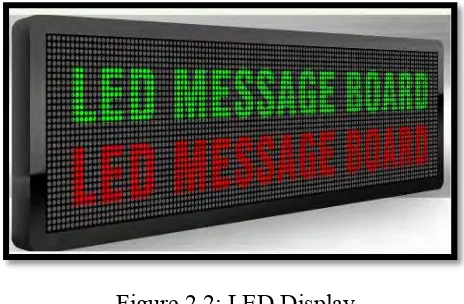
[image:22.595.208.427.304.445.2]LED and LCD are two technologies that are commonly used in various fields. Next, LED means Light Emitting Diode, which is a single component electronic device. The meaning of LCD is Liquid Crystal Display, which is a multi-component display device. Then, the application used for both devices are similar such as television, instrument display and indicator. Then, in order to complete this final year project, it is very important to have a better understanding in the concept and operation of LCD and LED. Figure 2.1 and Figure 2.2 below are the example of LCD and LED.
Figure 2.1: LCD Display
(Source: http://www.differencebetween.net/object/difference-between-lcd-and-led-televisions/ 22/4/2016)
Figure 2.2: LED Display
[image:22.595.201.433.497.649.2]6
2.2 Hardware
This topic will discuss several hardware platform as part of the literature review for the controller to be used in this project
2.2.1 Microcontroller
Microcontrollers used in world of industry to control various types of equipment, arrived from consumer to specific device. They has replaced microcontrollers old sort, including microprocessor. Moreover, there is need that is increasingly increasing for offline support for computer main processor. Request will grow as equipment that more use more intelligence. Application is from control modern car inboard engine to control laser printer and other computer hardware. Generally, many produce to achieve need for control. The, the most popular is Motorola 68HC11. This is because the 68HC11 microcontroller is relatively easy to work with, yet they have most of the features essential for a complete control system. This is because 68HC11 microcontroller that fairly simple to be working with, however they have most important features for full control system. Therefore, type of controller is easy. Although, futuristic vision to use processor that is newer, that 68HC11 is tool that is great to learn on control fundamentals. This micro guard offer a few functions that are suitable to plan electronic notice board. It is very flexible because it can expand for number that is unlimited port.
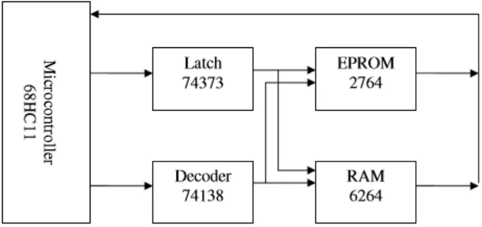
7 Figure 2.3: MC6811A1 Expanded Mode Block Diagram (Source: http://www.seattlerobotics.org/encoder/sep97/basics.html 24/4/2016)
From circuit above it comprises from microcontroller, latch, decoder, EPROM and RAM. After that, function latch is for demultiplex between data bus and address bus. Then, decoder used to choose input / output and memory. Modes grow normal activated by setting MODA and MODB in high logic condition. This carried out with directly connected to VCC through 4.7K resistance ohm. EPROM is memory that uncertain and commonly used to keep regular program or data. On the other hand, RAM is memory that uncertain and it only used for short storage.
2.2.2 Arduino