This is a repository copy of Cranial Reconstruction using Double Side Incremental Forming.
White Rose Research Online URL for this paper: http://eprints.whiterose.ac.uk/85765/
Version: Accepted Version
Article:
Lu, B., Xu, D.K., Liu, R.Z. et al. (3 more authors) (2015) Cranial Reconstruction using Double Side Incremental Forming. Key Engineering Materials, 639 . 535 - 542. ISSN 1013-9826
https://doi.org/10.4028/www.scientific.net/KEM.639.535
[email protected] https://eprints.whiterose.ac.uk/ Reuse
Unless indicated otherwise, fulltext items are protected by copyright with all rights reserved. The copyright exception in section 29 of the Copyright, Designs and Patents Act 1988 allows the making of a single copy solely for the purpose of non-commercial research or private study within the limits of fair dealing. The publisher or other rights-holder may allow further reproduction and re-use of this version - refer to the White Rose Research Online record for this item. Where records identify the publisher as the copyright holder, users can verify any specific terms of use on the publisher’s website.
Takedown
If you consider content in White Rose Research Online to be in breach of UK law, please notify us by
Cranial Reconstruction using Double Side Incremental Forming
B. Lu
1,2,a, D.K. Xu
2,b, R.Z. Liu
2,cH. Ou
3,d*, H. Long
1,eand J. Chen
2,f1Department of Mechanical Engineering, University of Sheffield, Sheffield, S1 3JD, UK
2
Department of Plasticity Technology, Shanghai Jiao Tong University, 1954 HuaShan Rd, Shanghai, 200030, China 3Department of Mechanical, Materials & Manufacturing Engineering, University of Nottingham, Nottingham, NG7 2RD, UK
a
[email protected], [email protected], [email protected], [email protected],
e[email protected], f[email protected]
Keywords: Incremental Sheet forming; Toolpath; Cranial reconstruction
Abstract. Incremental sheet forming (ISF) is a highly versatile and flexible process for rapid
manufacturing of complex sheet metal parts. Comparing to conventional sheet forming processes, ISF is of a clear advantage in manufacturing small batch or customized products such as cranial implant. Although effort on cranial reconstruction by using incremental sheet forming approach has been made in recent years, research has been mostly based on the single point incremental forming (SPIF) strategy and there are still considerable technical challenges for achieving better geometric accuracy, thickness distribution and complex cranial shape. In addition, the use of a backing plate or supporting die reduces the process flexibility and increases the cost. To overcome these limitations, double side incremental sheet forming (DSIF) process is employed for forming Grade 1 pure titanium sheet by using different toolpath strategies. The geometric accuracy and thickness distribution of the final part are evaluated so the optimized tool path strategies are developed. This leads to an assessment of the DSIF based approach for the application in cranial reconstruction.
Introduction
The skull, as a critical part of human anatomy, protects the encephalic area. The human skull may be impaired because of tumor or traumatic injuries. Cranioplasty is a surgical procedure for the repair of deformity of a human skull, which not only offers cosmetic and lifesaving benefits but also gives relief to psychological drawbacks and improves the life quality of patients [1]. In cranioplasty, technical readiness for clinical application, short lead time, low cost and ease of manufacture for alloplastic cranioplasty, a cranial surgical procedure by using non-biologic such as metallic materials, are important considerations [2]. Among all alloplastic materials, titanium continues to be a main stream material used in cranioplasty surgeries because of its excellent biocompatibility, resistance to infection, excellent material properties including strength and lightweight. Concerning the manufacture of titanium based cranial plates, there is a wide variety of methods including casting [3], manual shaping [4] and rubber press forming [5]. These processes need to manufacture customized casting moulds, templates and forming dies, which are not only costly but also time consuming [2]. In recent years, 3D printing or additive manufacturing based technologies have made rapid advances and it is possible to complete 3D printing of a cranial or a maxillofacial prosthetic part within several hours [6]. However, there are still a number of impediments including insufficient material properties and high cost issues to be overcome before its wide adoption for clinical applications [7].
In recent years, the incremental sheet forming (ISF) becomes an emerging technology in flexible forming of sheet part [8]. By employing Computer Numerical Control (CNC) systems with the minimum use of complex tooling and forming press, the ISF technology makes the process cost-effective and easy to automate. In the past decade, significant progress has been made in the research of ISF technology. Processes such as negative forming [9] and positive forming [10] as well as the hybrid forming by combining stretch forming and incremental sheet forming [11] are developed. The advances of ISF make it specially suitable for manufacture small-batch or customized components, such as those in automobile [12], aerospace [13] and medical application[14]. In recent years, efforts were made to use ISF to manufacture cranial reconstruction [15-19]. In the conventional
ISF process, only one tool is employed. Additional fixtures such as a backing plate or supporting die are usually required to ensure the geometric accuracy of formed part, which reduces the process flexibility as the fixture has to be prepared before ISF processing.
Another emerging method is double side incremental sheet forming (DSIF), in which two forming tools are employed at each side of the sheet. The DSIF process was first investigated by Meier et al employing two industrial robots [20, 21]. A DSIF machine was developed and an accumulative DSIF strategy was proposed by Cao et al [22]. With a developed DSIF machine, the comparison between DSIF and conventional SPIF were made [23]. The investigation suggested that the DSIF process can not only form a part with complex geometry but also increase the formability by squeezing the sheet. The obvious advantage of the DSIF process is that no additional supporting die or backing plate is required and a fully “dieless” forming can be achieved. While most of the DSIF investigations focus on material deformation, no research has been reported focusing on using DSIF based process for medical applications such as cranial reconstruction.
This paper studies the feasibility of producing customized cranial plates through the DSIF approach. In the paper, the procedure for geometric reconstruction of a cranial plate and the establishment of the CAD model for DSIF processing was investigated. Based on the established model, the DSIF forming strategies for cranial plate manufacture are discussed and the toolpath generation methods are developed and implemented. By using the experimental approach, cranial plates are produced. The geometric accuracy and the thickness distribution of the cranial plates processed by different means are compared and evaluated. Discussions on the feasibility of DSIF process on producing cranial plates are made to reach a number of conclusions for future work.
Methodologies
Geometric modeling of cranial plate. The cranial reconstruction begins with the repair of a skull
defect. The digital skull model may be constructed based on point cloud from X-ray computed tomography (X-ray CT). Concerning a human skull with defect as shown in Fig. 1(a), in order to repair the defective region of the skull, a few strategies may be employed such as mirroring the geometric data from one side of the skull to the other due to the symmetry of the skull or re-construction of the missing geometric shape from NURBS approximation [24]. In this work, the second approach was employed.
(a) Original model (b) Identification of surrounding area
Figure 1: Skull Geometric model for cranial implant
(a) Approximation of (b) NURBS approximation (c) Generation of supplement construction lines for curved hole filling surface for DSIF
Figure 2: Generation of DSIF model for cranial reconstruction
DSIF forming strategies. In the DSIF process, two counter tools are employed to provide extra
flexibility in the forming process. A few strategies have been proposed: Cao et al [22] developed an accumulative forming approach, in which in-out toolpath strategy was employed. Meier et al proposed two DSIF forming strategies including DSIF with peripheral support and DSIF with local support [25]. Concerning the cranial plate to be generated as shown in Fig. 2(c), the geometry is relatively simple and the good formability of pure titanium ensures successful forming of this part. Under such circumstances, the geometric accuracy becomes important in the process design. The accumulative DSIF strategy may not be suitable for this case due to the uncertainties in the geometric accuracy. In this work, DSIF with both local and peripheral supports are considered and the two strategies are designed, as shown in Fig. 3.
(a) Peripheral support (b) Local support Figure 3: DSIF strategies
In the peripheral support strategy as shown in Fig. 3a), a slave tool with flat nose is employed. The slave tool stays at the same z-level during the entire forming process. For the local support strategy as shown in Fig. 3b), the forming force generated by the master tool may be taken by the slave tool other than the sheet itself, which is beneficial for minimized springback.
Toolpath generation for DSIF process. Concerning the toolpath generation algorithms, Malhotra et
al [26] developed an automatic helical tool path generation algorithm for SPIF process based on a modified adaptive slicing algorithm. Zhu et al [27] discussed the calculation method of the spiral tool path interval with constant scallop height. Lu et al [28] developed an feature based toolpath for SPIF process using electricity field. These approaches are employed for SPIF process to generate only one toolpath. For the DSIF process, two synchronized toolpaths are required. In this work, the z-level slicing approach is employed based on following five steps:
3) For the peripheral support strategy, only the top layer of the contour in the slave tool side is included. The corresponding slave point of a master toolpath point can be obtained by picking the nearest or the farthest point on the first layer of salve contour.
4) For the local support, all the layers of the contour in both the master and slave tool sides are involved.
5) Generate spiral tool path by interpolating the two neighboring contours [28].
Using the above described approach, pairs of one-to-one correspondence points can be obtained and synchronization of the master and slave tool motions can be achieved for the DSIF process.
(a) Peripheral support (b) Local support Figure 4: DSIF Toolpath generation concept
Experiments
Experiment setup. A newly developed DSIF machine was used in this work as shown in Fig. 5. In
this machine, the master and slave tools are placed at each side of the sheet blank. Each tool is moved independently along their three axes, namely X, Y, Z and A, B, C for six degree of freedoms. The synchronization of the tools’ movement is achieved by a custom developed control system, which follows pre-defined two toolpaths for both the master and slave tools as mentioned in section 2.3.
(a) Developed DISF machine (b) Two tools and clamping system (c) DSIF with local support
Figure 5: DSIF machine and forming of cranial plate
In the experiment, Grade 1 pure titanium was used to produce the cranial implant. As high contact stress may occur at the tool-sheet interface, roller ball tools were employed to reduce the friction and improve the surface quality. Using the developed geometric model and toolpaths, the cranial plates were formed using different strategies as shown in Fig. 6(a). By trimming the blanking area, a finished cranial plate can be obtained as shown in Fig. 6(b).
Geometric accuracy. To evaluate the geometric accuracy, cross-sections of finished parts are
measured in both X and Y directions as given in Fig. 6(a) and compared with the designed shape as shown in Fig. 7. It can be found that the formed part matched the designed geometric in most of the region after forming process. However, without a backing plate, geometric inaccuracy can be observed at the top edge for all the cases as shown from the red arrows. The maximum error could reach 5mm. This is caused by the bending effect at the initial stages. Concerning the differences between peripheral and local supports, discrepancy can be observed at positions 1 and 3 in Fig. 7. This result suggested that although a second tool is involved in the DSIF process, it cannot fully overcome the initial bending problem without a backing plate. This is because: 1) the slave tool can only locally support the sheet at one point but not the whole shoulder area; 2) springback occurs after releasing the part from clamp which produces additional geometric deviation. Furthermore, “over-compensation” for the slave toolpath at the top edge area may not be sufficient to minimise this error. However, these regions may be trimmed at later stage in cranial construction.
e
i
(a) X cross-section (b) Y cross-section
Figure 7: Comparison of cross-section profile for each case after forming
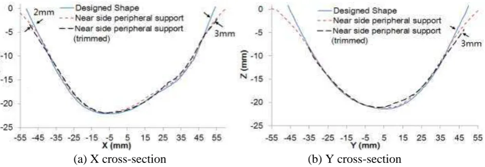
Further investigations on the geometric accuracy are made for trimmed part with near side peripheral support, as shown in Fig. 8. Obvious springback can be observed after removing the blank. The maximum deviation occurs along the trimmed edge with the value of about 3mm in both X and Y cross-sections. This springback may be due to the reduced stiffness around the edge after trimming and re-distribution of the residual stress. This result suggested that potential geometric inaccuracy of the cranial plate after the ISF processing. Further optimisation on toolpath strategy may be used to minimise the occurrence of residual stress and additional shape compensation may reduce the springback to a lower level.
[image:6.595.66.539.557.720.2](a) X cross-section (b) Y cross-section
Figure 8: Comparison of cross-section profile for near side peripheral support part after trimming
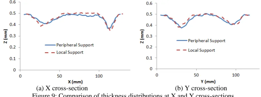
Thickness distribution. Thickness distribution could potentially affect the stiffness of the cranial
thickness distributions can be observed for the two formed parts, the maximum thickness reduction for the local support reaches 30% at a certain point whilst this for the peripheral support is about 20%. This difference may be caused by the tool squeezing during the forming process in the local support strategy. These results suggested that the peripheral support cases produced better thickness distribution than that obtained from the local support.
[image:7.595.64.522.154.325.2]
(a) X cross-section (b) Y cross-section Figure 9: Comparison of thickness distributions at X and Y cross-sections
Surface roughness. As another important aspect in evaluation of the sheet part quality, the surface
finishes from different DSIF tooling strategies are shown in Fig. 10. It can be found that obvious tool marks can be observed for the part processed by the case with the local support. This tool marks were caused by the tool squeezing applied to the sheet causing higher contact pressure and larger friction. Concerning the parts processed by the peripheral support, the tool marks are not as obvious as those from the local support, which suggested a better surface quality. This result suggested that although the local support might result in a better formability due to the squeezing effect [25], the peripheral support strategy may be superior in terms of the surface finish especially for materials such as Grade 1 pure titanium.
(a) Peripheral support (b) Local support Figure 10: Comparison of surface finish for finished parts
Discussion and Conclusions
suggested that the peripheral support strategy could provide cranial plate with a better quality in both geometric accuracy and surface finish. The conclusions of this work may be summarized as follows:
1) The developed surface approximation procedure including approximation of the construction
curves and fitting of the NURBS based surfaces was proven to be a feasible approach in the geometric reconstruction of cranial shape.
2) The peripheral support strategy was considered as a better option as compared to the local support in using DSIF to manufacture the cranial plate in terms of geometric accuracy, thickness distribution and surface finish.
3) Double side increment forming could produce the cranial plates without using a backing plate,
which suggested considerable benefits in the application of cranial reconstruction.
Acknowledgement
The authors are grateful for the support provided by the Engineering and Physical Science Research Council of UK (EP/L02084X/1) and the Marie Curie International Incoming Fellowship (628055 & 913055) and International Research Staff Exchange Scheme (IRSES, MatProFuture project, 318968) within the 7th EC Framework Programme (FP7).
References
1. S. Aydin, B. Kucukyuruk, B. Abuzayed, S. Aydin, and G. Sanus, Cranioplasty: Review of materials and techniques, J. Neurosci. Rural Pract. 2 (2011) 162-167.
2. U. Spetzger, V. Vougioukas, and J. Schipper, Materials and techniques for osseous skull reconstruction, Mini. Invasive Thero. Allied Technol., 19 (2010) 110-121.
3. E. Heissler, F.S. Fischer, S. Bolouri, T. Lehmann, W. Mathar, A. Gebhardt, W. Lanksch, and J. Bier, Custom-made cast titanium implants produced with CAD/CAM for the reconstruction of cranium defects, Int. J. Oral Maxillofac. Surg., 27 (1998) 334-338.
4. D. Bhargava, P. Bartlett, J. Russell, M. Liddington, A. Tyagi, and P. Chumas, Construction of titanium cranioplasty plate using craniectomy bone flap as template, Acta Neurochirurgica., 152 (2010) 173-176.
5. J. Joffe, M. Harris, F. Kahugu, S. Nicoll, A. Linney, and R. Richards, A prospective study of computer-aided design and manufacture of titanium plate for cranioplasty and its clinical outcome, Br. J. Neurosurg., 13 (1999) 576-580.
6. H. Rotaru, H. Stan, I.S. Florian, R. Schumacher, Y.-T. Park, S.-G. Kim, H. Chezan, N. Balc, and M. Baciut, Cranioplasty With Custom-Made Implants: Analyzing the Cases of 10 Patients, J. Oral & Maxillofac. Surg., 70 (2012) 169-176.
7. M.H. Elahinia, M. Hashemi, M. Tabesh, and S.B. Bhaduri, Manufacturing and processing of NiTi implants: A review, Prog. in Mat. Sci., 57 (2012) 911-946.
8. J. Jeswiet, Asymmetric Incremental Sheet Forming, Adv. Mat. Res., 6-8 (2005) 35-58.
9. H. Iseki, K. Kato, and S. Sakamoto, Flexible and incremental sheet metal forming using a spherical roller, In: Proc. 40th JJCTP. (1989) 41–44 (in Japanese).
10. S. Matsubara, Incremental Backward Bulge Forming of a Sheet Metal with a Hemispherical Head Tool, J. JSTP, 35 (1994) 1311-1316.
12. W.B. Lievers, A.K. Pilkey, and D.J. Lloyd, Using incremental forming to calibrate a void nucleation model for automotive aluminum sheet alloys, Acta Materialia., 52 (2004) 3001-3007.
13. G. Hussain, H.R. Khan, L. Gao, and N. Hayat, Guidelines for Tool-Size Selection for Single-Point Incremental Forming of an Aerospace Alloy, Mat. & Manuf. Process., 28 (2012) 324-329.
14. G. Ambrogio, L. De Napoli, L. Filice, F. Gagliardi, and M. Muzzupappa, Application of Incremental Forming process for high customised medical product manufacturing, J. Mat. Process. Technol., 162-163 (2005) 156-162.
15. J.R. Duflou, B. Lauwers, J. Verbert, F. Gelaude, and Y. Tunckol, Medical Application of Single Point Incremental Forming: Cranial Plate Manufacturing, in Proc. 2nd Int. Conf. Adv. Res. Virtual and Rapid Prototyping, 2005, pp.161-166.
16. R. Araújo, P. Teixeira, M.B. Silva, A. Reis, and P.A.F. Martins, Single point incremental forming of a medical implant, Key Eng. Mat., 544–557 (2013) 1388–1393.
17. A. Göttmann and M. Korinth, Manufacturing of cranial implants using incremental sheet metal forming, in Proc. 1st Int. Conf. on Design and Processes for Medical Devices (PROMED), 2012, pp.287-290.
18. B. Lu, H. Ou, S.Q. Shi, H. Long, and J. Chen, Titanium based cranial reconstruction using incremental sheet forming, Int. J. Mat. Form., (2014) (online first).
19. J.R. Duflou, A.K. Behera, H. Vanhove, and L.S. Bertol, Manufacture of Accurate Titanium Cranio-Facial Implants with High Forming Angle Using Single Point Incremental Forming, Key Eng. Mat., 549 (2013) 223-230.
20. H. Meier, V. Smukala, O. Dewald, and J. Zhang, Two Point Incremental Forming with Two Moving Forming Tools, Key Eng. Mat., 344 (2007) 599-605.
21. H. Meier, C. Magnus, and V. Smukala, Impact of superimposed pressure on dieless incremental sheet metal forming with two moving tools, CIRP Ann. - Manuf. Technol., 60 (2011) 327-330.
22. R. Malhotra, J. Cao, M. Beltran, D. Xu, J. Magargee, V. Kiridena, and Z.C. Xia, Accumulative-DSIF strategy for enhancing process capabilities in incremental forming, CIRP Ann. - Manuf. Technol., 61 (2012) 251-254.
23. J. Smith, R. Malhotra, W.K. Liu, and J. Cao, Deformation mechanics in single-point and accumulative double-sided incremental forming, Int. J. Adv. Manuf. Technol., 69 (2013) 1185-1201.
24. L. Piegl and W. Tiller, The NURBS book. 2nd ed. 1997, Berlin, New York: Springer.
25. H. Meier, B. Buff, R. Laurischkat, and V. Smukala, Increasing the part accuracy in dieless robot-based incremental sheet metal forming, CIRP Ann. - Manuf. Technol., 58 (2009) 233-238.
26. R. Malhotra, N.V. Reddy, and J. Cao, Automatic 3D Spiral Toolpath Generation for Single Point Incremental Forming, ASME J. Manuf. Sci. & Eng., 132 (2010) 061003.
27. H. Zhu, Z. Liu, and F. J., Spiral tool-path generation with constant scallop height for sheet metal CNC incremental forming, Int. J. Adv. Manuf. Technol. (2011) (online first).