rogramming with
omain ra hies
rimitives
Apollo Computer Inc. 330 Billerica Road Chelmsford, MA 01824
Copyright © 1987 Apollo Computer Inc. All rights reserved. Printed in U.S.A. First Printing:
First Revision: Latest Printing:
July, 1985 February, 1987 August, 1987
This document was produced using the Interleaf Workstation Publishing Software (WPS) , and the InterCAD 2040 Electronic illustrating System, a product of lnterCAD Corporation. Interleaf and WPS are trademarks of Interleaf, Inc.
Apollo and Domain are registered trademarks of Apollo Computer Inc.
UNIX Is a registered trademark of AT&T In the USA and other countries. Ada Is a registered trademark of U.S. Government (Ada Joint Program Office).
3DGR, Aegis, D3M, DGR, Domain/Access, Domain/Ada, Domain/Bridge, Domaln/C, Domaln/ComController, Domaln/CommonLlSP, Domain/CORE, Domain/Debug, Domaln/DFL, Domain/Dialogue, Domain/DQC, Domain/IX, Domaln/Laser-26, Domain/LiSP, Domaln/PAK, Domaln/PCC, Domain/PCC-Remote, Domain/PCI, Domain/SNA, Domaln/X.25, DPSS/Mail, OSEE, FPX, GMR, GPR, GSR, NCK, NCS, Network Computing Kernel, Network Computing System, Open System Toolkit, OST, Personal Workstation, and Series 3000 are trademarks of Apollo Computer Inc. Apollo Computer Inc. reserves the right to make changes In specifications and other information contained In this publication without prior notice, and the reader should In all cases consult Apollo Computer Inc. to determine whether any such changes have been made.
THE TERMS AND CONDITIONS GOVERNING THE SALE OF APOLLO COMPUTER INC. HARDWARE PRODUCTS AND THE IJCENSING OF APOLLO COMPUTER INC. SOFTWARE PROGRAMS CONSIST SOLELY OF THOSE SET FORTH IN THE WRITTEN CONTRACTS BETWEEN APOLLO COMPUTER INC. AND ITS CUSTOMERS. NO REPRESENTATION OR OTHER AFFIRMATION OF FACT CONTAINED IN THIS PUBLICATION, INCLUDING BUT NOT LIMITED TO STATEMENTS REGARDING CAPACITY , RESPONSE-TIME PERFORMANCE , SUITABILITY FOR USE OR PERFORMANCE OF PRODUCTS DESCRIBED HEREIN SHALL BE DEEMED TO BE A WARRANTY BY APOLLO COMPUTER INC. FOR ANY PURPOSE, OR GIVE RISE TO ANY LIABILITY BY APOLLO COMPUTER INC. WHATSOEVER.
IN NO EVENT SHALL APOLLO COMPUTER INC. BE LIABLE FOR ANY INCIDENTAL, INDIRECT, SPECIAL OR CONSEQUENTIAL DAMAGES WHATSOEVER (INCLUDING BUT NOT LIMITED TO LOST PROFITS) ARISING OUT OF OR RELATING TO THIS PUBLICATION OR THE INFORMATION CONTAINED IN IT, EVEN IF APOLLO COMPUTER INC. HAS BEEN ADVISED, KNEW OR SHOULD HAVE KNOWN OF THE POSSIBILITY OF SUCH DAMAGES.
This manual describes the Domain graphics primitive resource (GPR) system. It shows how to use graph-ics primitive routines in applications programs.
We've organized this manual as follows:
Chapter 1
Chapter 2
Chapter 3
4
Chapter S
Chapter 6
Chapter 7
Chapter 8
Chapter 9
Chapter 10
Chapter 11
Appendix A
Appendix B
ADDelncUX C
Appendix D
Appendix E
Presents an overview of GPR and its capabilities.
Shows you how to get started writing GPR programs. It also explains the various display modes that GPR can run in.
Describes how to use GPR routines to display geometric shapes such as lines, arcs, splines, circles, and polygons.
Demonstrates how to print text in a graphics program.
Details bitmaps.
Details color on the GPR system.
Explains how GPR analyzes input events such as moving the mouse or typing keys on the keyboard.
Describes the cursor.
Describes clip windows and plane masks.
Details direct mode (which lets you run GPR programs in a window).
Explains raster operations.
Illustrates the keyboards and contains keyboard charts.
Presents the Pascal program examples used in the manual translated into C.
Presents the Pascal program examples used in the manual translated into FORTRAN.
Lists the amount of visible and hidden display memory for each node type, and also lists the number of planes available for each node type.
Describes decomposition techniques.
Manuals
This is one of three manuals that compose the GPR documentation set. The other two are
• Domain Graphics Primitive Resource Call Reference (007194) which details the syntax for every GPR call.
• Domain GPR Quick Reference (010430) which provides terse descriptions of each GPR call.
In addition, the following manuals may also prove useful to GPR programmers:
• Programming with General System Calls (005506) explains pad calls and how to emulate Pascal data types (for example, sets) in C and FORTRAN.
• Domain C Language Reference (002093) explains how to program in the Domain C language.
• Domain Pascal Language Reference (000792) explains how to program in the Domain Pascal lan-guage.
• Domain FORTRAN Language Reference (000530) explains how to program in the Domain FOR-TRAN language.
On-Line Examples
Because this manual is being published between software releases, we will not be able to provide customers with the on-line versions of the sample programs until the next software release. For details regarding these programs, look in the GPR section of the next standard release notes.
Problems, Questions, and Suggestions
We appreciate comments from the people who use our system. In order to make it easy for you to com-municate with us, we provide the User Change Request (UCR) system for software-related comments, and the Reader's Response form for documentation comments. By using these formal channels you make it easy for us to respond to your comments.
You can get more information about how to submit a UCR by consulting the DOMAIN System Command
Reference. Refer to the CRUCR (CREATE_USER_CHANGE_REQUEST) Shell command description. You can view the same description on-line by typing:
$ HELP CRUCR <RETURN>
For your documentation comments, we've included a Reader's Response form at the back of each manu-al.
Documentation Conventions
Unless otherwise noted in the text, this manual uses the following symbolic conventions.
UPPERCASE
output
< >
CTRL/Z
Bold, uppercase words or characters in formats and command descriptions repre-sent commands or keywords that you must use literally.
Typewriter font words are used for sample programs and command examples.
Angle brackets enclose the name of a key on the keyboard.
The notation CTRLI followed by the name of a key indicates a control character sequence. You should hold down <CTRL> while typing the character.
Chapter 1 Overview of GPR
1.1 Overview of GPR Capabilities . . . 1-1 1.2 Characteristics of Graphics Primitives . . . 1-2
Chapter 2 Getting Started with GPR Programming
2.1 Writing GPR Application Programs . . . 2-1 2. 1.1 Including Insert Files . . . 2-2 2.1.2 Calling the gpr_$init Routine . . . 2-2 2.1.3 Calling the gpr_$terminate Routine . . . ' ... 2-3 2.1.4 Calling the gpr_$inCLdisp_characteristics Routine . . . 2-3 2.2 Sample GPR Programs . . . , . . . 2-3 2.2.1 Pascal Example . . . 2-4 2.2.2 C Example . . . 2-6 2.2.3 FORTRAN Example . . . ' . . . 2-8 2.3 Display Modes . . . 2-9 2.3.1 Borrow Mode . . . ' . . . 2-10 2.3.2 Direct Mode .' . . . 2-10 2.3.3 Frame Mode . . . , . . . 2-11 2.3.4 No-Display Mode . . . 2-12
Chapter 3 Drawing Figures
3.1 The GPR Coordinate System . . . 3-2 3. 1. 1 Current Position . . . 3-2 3.2 Lines . . . 3-3 3.2.1 A Program to Demonstrate gpr_$line and gpr_$move . . . 3-4 3.2.2 A Program to Draw Connected Lines . . . 3-5 3.2.3 A Program to Draw Disconnected Lines . . . 3-6 3.3 Circles . . . 3-7 3.4 Arcs . . . 3-8 3.5 Splines . . . 3-10 3.6 Filled Polygons . . . 3-11 3.6.1 Creating a Tile Pattern . . . 3-15 Tile Patterns on Monochromatic Nodes . . . 3-15 Tile Patterns on Color Nodes -- Method 1 . . . 3-15 Tile Patterns on Color Nodes -- Method 2 . . . 3-17 3.7 Wide Lines, Arcs, Circles, and Splines . . . 3-17 3.8 Solid and Dashed Lines . . . 3-1 7 3.9 Summary . . . 3-20
Chapter 4 Printing Text
Bitmaps 5-1
5.1 Overview of Bitmaps . . . 5-2 5.2 Display Memory Bitmaps . . . 5-2 5.2.1 How Images Are Displayed: a Tutorial . . . 5-3 5.3 Hidden Display Memory (HDM) Bitmaps . . . 5-3 5.3.1 Allocating an HDM Bitmap By Calling gpr_$allocate_hdm_bitmap . . . 5-4 5.3.2 Using HDM By Elongating the Initial Bitmap . . . 5-5 5.4 Main Memory Bitmaps . . . 5-8 5.4.1 How to Create a Main Memory Bitmap . . . 5-8 5.5 External File Bitmaps . . . 5-5 5.5.1 How to Create an External File Bitmap . . . 5-5 5.6 Double-Buffer Bitmaps . . . 5-13
5.6.1 Availability of Double Buffering . . . 5-13 5.6.2 GPR Calls Controlling Double Buffering . . . 5-13 5.6.3 Nuances of Double-Buffer Programming . . . 5-14 5 . 6 . 4 Double Buffering Example . . . 5 -14 5.7 Removing Bitmaps . . . 5-17 5.8 The Current Bitmap . . . 5-17 5.9 Block Transfers (BLTs) . . . 5-17 5.10 Attributes and Attribute Blocks ... , . . . 5-19 5. 10.1 Attribute Blocks in Double-Buffer Bitmaps . . . 5 - 21 5.10.2 A List of Attributes Stored Inside Attribute Blocks . . . 5-21 5.10.3 Attributes Stored with the Bitmap . . . 5-24 5.11 Translating Bitmaps to and from Arrays . . . 5-24 5.12 -Manipulating a Bitmap Through a Bitmap Pointer . . . 5-26 5.12.1 Manipulating a Main Memory Bitmap Through a Bitmap Pointer . . . 5-26 5.12.2 Manipulating a Display Memory Bitmap Through a Bitmap Pointer ... 5-27 5.12.3 Manipulating a Hidden Display Memory Bitmap Through a Bitmap ... 5-29
Chapter 6 Color
Chapter 7 Input Events
7.1 What is an Event? . . . ., . . . 7-1 7.1.1 Kinds of Events . . . ., . . . 7-1 7.2 Reporting Input Events . . . ., . . . 7-2 7.2.1 Enabling Input Events . . . " . . . 7-2 7.2.2 Waiting for an Event to Occur ... , . . . 7 - 3 7.2.3 Sample Event Programs . . . 7-4 7.3 Using EC2 Calls . . . " . . . , ... 7-6 7.4 Input Events When a Program Runs in Multiple Windows . . . ,... 7-6 7.4.1 Creating a GPR Program That Runs in Multiple Windows . . . 7-6 7.4.2 Monitoring Input Events . . . 7-6 7.5 Adjusting the Input Stream . . . , . . . 7-8
Chapter 8 The Cursor
8.1 Overview of the Cursor . . . 8-1 8.2 Display Mode and Cursor Control . . . 8-1 8.3 How to Control The Cursor In Your GPR Program . . . 8-2 8.4 Cursor Origin . . . , . . . 8-4 8.5 Inquiring About the Cursor . . . 8-5 8.6 Tracking the Cursor . . . , . . . 8-5
Chapter 9 Clip Windows and Plane Masks
9.1 What Is a Clip Window? . . . 9-1 9.2 Default Clip Window Size . . . 9-2 9.3 Enabling and Disabling the Clip Window . . . 9-2 9.4 How to Establish a Nondefault Clip Window . . . 9-2 9.5 Multiple Clip Windows . . . 9-4 9.6 Clip Windows in Double-Buffer Bitmaps . . . 9-4 9.7 Setting Plane Masks . . . 9-4 9.8 Inquiring About Plane Masks and Clip Windows . . . 9-5
Chapter 10 Direct Mode
10.1 Acquiring and Releasing the Display . . . 10-1 10.1.1 Acquire Time Out . . . 10-3 10.2 If the Window Becomes Obscured . . . 10-3 10.2.1 Drawing in the Nonobscured Parts of a Partially Obscured Window ... 10-4 10.3 Refreshing a Window . . . 10-6 10.3.1 Refreshing a Window in a Double-Buffer Application ... . . . 10-8 10.4 How to Use High-Level I/O Commands . . . 10-8
Chapter 11 Raster Operations
Appendix A Keyboards
Appendix B C Programs
The Include File Used By All Sample C Programs . . . B-2 A Simple GPR Program To Get Started . . . B-3 A Program To Draw a Simple Line . . . B-4 A Program To Draw Connected Lines . . . B-5 A Program To Draw Disconnected Lines . . . B-6 A Program To Draw Two Circles . . . B-7 A Program To Draw Two Arcs . . . B-8 A Program To Draw a Spline . . . B-9 A Program To Draw a Filled Triangle, Rectangle, and Trapezoid . . . B-10 A Program To Draw a Filled Polygon . . . B-11 A Program To Create and Use a Nondefault Tile Pattern . . . B-12 A Program To Draw Thick and Dashed Lines . . . B-13 A Program To Write a Simple String to the Display . . . B-14 A Program That Uses More Than One Text Font . . . B-15 A Program That Writes Text in Different Directions . . . B-16 A Program That Modifies a Text Font's Characteristics . . . B-17 A Program To Create a Hidden Memory Bitmap . . . B-18 A Program That Toggles Between Frame 0 and Frame 1 . . . B-19 A Program That Creates a Main Memory Bitmap . . . B-20 A Program That Creates a Pixel Oriented External File Bitmap . . . B-21 A Program That Demonstrates Double-Buffer Techniques . . . B-23 A Program That Demonstrates The Three Different Kinds of Block Transfers (BLTs) .. B-26 A Program That Sets and Employs Two Attribute Blocks for the Same Bitmap ... B-28 A Program That Converts a Color Bitmap to an Array, Manipulates the Array,
and Converts the Array Back to a Bitmap . . . B-29 A Program That Manipulates a Main Memory Bitmap Through a Bitmap Pointer ... B-30 A Program That Manipulates a Display Memory Bitmap Through a Bitmap Pointer .... B-31 A Program That Manipulates a Hidden Display Memory Bitmap Through a Bitmap
Pointer . . . B-32 A Program That Draws a Line, Fills a Triangle, and Writes Some Text in Different
Colors . . . B-34 A Program That Alters the Color Map . . . B-35 A Program That Saves the Original Color Map, Loads a New Color Map. and Then
Appendix C FORTRAN Programs
The File That Must Be Bound With All Sample FORTRAN Programs . . . C-l The Common Block That Must Be Included In Every Sample Program . . . C-2 A Simple GPR Program To Get Started . . . C-3 A Program To Draw a Simple Line . . . C-4 A Program To Draw Connected Lines . . . C-5 A Program To Draw Disconnected Lines . . . C-6 A Program To Draw Two Circles . . . C-7 A Program To Draw Two Arcs . . . C-8 A Program To Draw a Spline . . . C-9 A Program To Draw a Filled Triangle, Rectangle, and Trapezoid . . . C-I0 A Program To Draw a Filled Polygon . . . C-ll A Program To Create and Use a Nondefault Tile Pattern . . . C-12 A Program To Draw Thick and Dashed Lines ... " . . . C-14 A Program To Write a Simple String to the Display' . . . C-15 A Program That Uses More Than One Text Font . . . C-16 A Program That Writes Text in Different Directions . . . C-17 A Program That Modifies a Text Font's Characteristics . . . C-18 A Program To Create a Hidden Memory Bitmap . . . C-19 A Program That Toggles Between Frame 0 and Frame 1 . . . C-21 A Program That Creates a Main Memory Bitmap . . . C-22 A Program That Creates a Pixel Oriented External File Bitmap . . . C-24 A Program That Demonstrates Double-Buffer Techniques . . . C-2 7 A Program That Demonstrates The Three Different Kinds of Block Transfers (BLTs) .. C-30 A Program That Sets and Employs Two Attribute Blocks for the Same Bitmap. '.' ... C-32 A Program That Converts a Color Bitmap to an Array, Manipulates the Array,
and Converts the Array Back to a Bitmap . . . C-34 A Program That Manipulates a Main Memory Bitmap Through a Bitmap Pointer ... C-35 A Program That Manipulates a Display Memory Bitmap Through a Bitmap Pointer .... C-36 A Program That Manipulates a Hidden Display Memory Bitmap Through a Bitmap
Pointer . . . C-3 7 A Program That Draws a Line, Fills a Triangle, and Writes Some Text in Different
Colors . . . C-38 A Program That Alters the Color Map . . . C-39 A Program That Saves the Original Color Map, Loads a New Color Map, and Then
Appendix D Node-Dependent Data
D.l Limitations . . . D-2
Appendix E Decomposition and Rendering Techniques
E.l The Need for New Decomposition Techniques . . . E-l E .1.1 Decomposition Versus Rasterization . . . E-2 E.1.2 Comparing the Techniques . . . E-2 Triangle versus Trapezoid Decomposition . . . E-2 Triangle versus Render-Exact Techniques . . . E-7 E.2 Filling Polygons . . . E-9 E.2.1 Filling Polygons with the Triangle and Render-Exact Techniques . . . E-9 E.2.2 Filling Polygons with the Trapezoid Technique . . . E-l0 E.3 Polygons From Start to Fill . . . E-l1 E.4 The Default Decomposition Techniques . . . E-12 E.5 Performance Considerations . . . E-12 E.6 Limitations . . . E-13 E.7 Sample Programs . . . E-14 E.7.1 Program to Set the Decomposition Technique . . . E-14 E.7.2 Sample Program to Draw a Polygon . . . E-15
Appendix F Imaging Mode
F.l What is Imaging Mode . . . F-l F.2 Selecting Between Interactive Mode and Imaging Mode . . . F-2 F.3 Writing to a Bitmap in Imaging Mode . . . F-2 FA Using Color in Imaging Mode .... , . . . F-2 F.5 Using gpr_$select_color_frame . . . F-2
Figure 3-1 3-2 3-3 3-4 3-5 3-6 3-7 3-8 3-9 4-1 4-2 4-3 5-1 5-2 6-1 6-2 6-3 6-4 6-5 6-6 6-7 6-8 8-1 9-1 9-2 10-1 10-2 A-1 B-1 E-2 E-3 E-4 E-5 E-6 B-7 B-8 E-9 E-10 E-11 E-12 E-13
How GPR Views Coordinates . . . 3-2 Using gpr_$line and gpr_$move to Create Two Lines . . . 3-4 Using gpr_$polyline to Create Three Connected Lines . . . 3-5 Using gpr_$multiline to Draw Three Disconnected Lines . . . 3-6 Using gpr_$circle and gpr_$circle_filled to Draw Two Circles . . . 3-8 Using gpr_$arc_3p and gpr_$arc_c2p to Draw Two Arcs . . . 3-10 Using gpr_$triangle, gpr_$rectangle, and gpr_$trapezoid . . . 3-13 Using gpr_$startygon, gpr_$pgonyolyline, and gpr_$close_fillygon to
Create Filled Polygons . . . 3-14 Using gpr_$draw_width, gpr_$set_lineyattern, and gpr_$set_linestyle ... 3-19 Text Can Be Printed in Four Different Directions . . . 4-5 Measurements Returned by gpr_$in~text_extent , . . . 4-8 Measurements Returned by gpr_$in~text_offset ... , . . . 4-8 How a Raster Graphic System Generates an Image . . . 5-3 Bitmap Dimensions on an Elongated Initial Bitmap ... " . . . 5-6 Format of an Entry in a Color Map . . . , . . . 6-2 A Sample Entry for White in a Color Map . . . 6-2 Relationship of Monochrome Display Memory Bitmap to Pixels on the Monitor ... 6-3 Each Pixel on a 4-plane System Is Represented by 1 Bit in Each of 4 Planes ... 6-5 The Colors of the Pixels given the Plane Values Shown in Figure 6-4 and the
Color Map Shown in Table 6-1 . . . 6-6 The Linear Ramp Color Map . . . 6-20 True-color Color Map Look-up . . . 6-21 Color Zoom . . . 6-23 Relationship of Cursor Position and Cursor Origin . . . 8-5 A Clipping Window Masks Out a Portion of The Bitmap . . . 9-2 A Clipped Circle . . . 9 - 3 The gpr_$in~vis_list Routine Returns Six Rectangles Composing the Nonobscured
Portions of This Window . . . 10-4 The Input Pad and the Window Pad in a Direct Mode Program . . . 10-8 Low-Profile Keyboard . . . A-1 A Polygon Decomposed into Triangles and Trapezoids . . . E-2 The Pixels Rendered for a Trapezoid with the Trapezoid Technique ... E-3 Interior Pixels of a Six-sided Polygon Decomposed into Trapezoids ... E-4 Six-sided Polygon Decomposed and Rendered with the Trapezoid Technique.
The Raster Operations was Set to XOR. . . . E-4 Two Adjacent Six-sided Polygons Decomposed into Trapezoids . . . E-5 Two Adjacent Six-sided Polygons Decomposed and Rendered with the Trapezoid
Table
2-1 2-2 2-3 2-4 2-5 3-1 3-2 3-3 6-1 6-2 6-3 6-4 6-5 6-7 7-1 11-1 11-2 11-3 11-4
A-1
D-1 E-1 E-2 F-1
Tables
Page
1
f
The Graphics Primitives Resource package (GPR for short) is a set of well over 100 routines callable from your Domain FORTRAN, Domain Pascal, or Domain C program. Although these routines are relatively primitive, you can use combinations of them to write powerful, high-performance graphics applications. These routines are a standard piece of Domain software. The system stores these routines in an installed library at pathname llib/gprlib. An installed library is an object file whose routines are accessed at run-time. In other words, you do not have to load these routines at bind time; the system will load them auto-matically at runtime.
1.1
verview
Capabilities
GPR can
.. Draw lines, arcs, circles, splines, filled polyg.ons, and unfilled polygons. .. Load text fonts and write text strings.
.. Create and manipulate bitmaps in visible display memory, hidden display memory, main memory, and disk files.
.. Perform high-speed bit block transfers (BL Ts) between bitmaps or within a single bitmap. .. Monitor "events" such as mouse movement and keyboard input.
.. Control the system color map.
.. Generate a nondefault cursor pattern and place it anywhere on the screen. .. Refresh a window that has been obscured by other windows.
1
Graphics primitives are device-dependent with respect to the display. However. they are independent of the various display environments. The operating system also provides pad calls (which all begin with the prefix pad_$); these calls allow you to create pads and frames. However, you cannot use pad calls to gen-erate graphics. For a description of pad calls, see Programming with General System Calls.
GPR routines are independent of the display environments in two ways. First, you can run a program which uses GPR routines on any of the displays. Second, graphics programs can issue pad calls. There-fore, if you use the graphics primitives routines, you can easily change program execution from one display mode to another by changing one option in the GPR initialization routine gpr_$init.
i
This chapter will get you started writing GPR programs in FORTRAN, Pascal, or C. We explain the essen-tials for a successful GPR program. This chapter also explains all the display modes, and the various trade-offs in choosing one display mode over another. This chapter demonstrates the calls shown below:
gpr_$init gpr _ $terminate
gpr _ $in~ config gpr _ $in~ disp _characteristics
1
You can write a GPR program in FORTRAN, Pascal, or C. Regardless of the language, all GPR programs must have the minimum structure shown in Table 2-1.
Table 2-1. Structure of a GPR Program
FORTRAN program gpr _example %include '/sys/inslbase.ins.ftn' %include '/sys/ins/gpr.ins.ftn'
call gpr_$init( . . . )
'(zero or more GPR . calls or other code.) call gpr _ $terminate ( . . . )
Pascal program gpr_example;
%include '/sys/inslbase.ins.pas'; %include '/sys/insl gpr .ins. pas' ;
gpr_$init( . . . );
. (zero or more GPR . calls or other code.) gpr _ $terminate (. . .);
C
#include "/sys/ins/base.ins.c" #include "/sys/ins/gpr.ins.c"
gpr_$init( . . . );
The minimum requirements for a GPR program are to: .. include two insert files.
.. call the gpr_$init routine. .. call the gpr _ $terminate routine.
In addition to these requirements, we also recommend that you call the gpr_$inCLdisp_characteristics rou-tine.
2.1.1 Including Insert Files
In order to write GPR application programs, you must include at least two insert files. The first one defines certain commonly used system declarations. It must be one of the following:
FORTRAN
Pascalc
I sys/ins/base. ins. ftn I sys/ins/base. ins. pas I sys/ins/base. ins. c
The second insert file allows you to use GPR routines. It must be one of the following:
FORTRAN
Pascalc
Isys/insl gpr .ins. ftn I sys/insl gpr . ins. pas Isys/ins/gpr .ins.c
At times you may need other insert files. For example, if you use pad calls within your GPR program, you must include the appropriate pad insert file. You may also want to create your own insert files to facilitate variable declarations. If you consistently use a particular set of variables, you can put them in an insert file and then include the insert file in any program that uses those variables.
Many of the programming examples used in this manual include the following insert file:
FORTRAN
Pascalc
I sys/insltime. ins. ftn I sys/ins/time . ins. pas I sys/ins/time. ins. c
This enables the programs to use the TIME_$WAIT routine, which keeps an image displayed on the screen for a specified period of time.
Another insert file which should be included in all GPR programs is an error insert file. The error insert file is required if you want to check for system errors. It is recommended that you check for system errors after every system call.
FORTRAN
Pascalc
I sys/insl error. ins. ftn Isys/ins/error .ins. pas I sys/insl error. ins. c
2 .. 1.2 Calling the gpr _ $init Routine
To execute GPR calls in an application program, you must first initialize the package. You do this by call-ing the routine gpr_$init in the application program. You are allowed to perform non-GPR operations be-fore initializing GPR, but you cannot execute any GPR routines except gpr_$inCLconfig and gpr_$inCLdisp_characteristics until GPR is initialized.
2.1.3 Calling the gpr _ $terminate Routine
Use gpr_$terminate to finish your GPR session. After calling gpr_$terminate you cannot call any other GPR routines until you reinitialize the package with gpr_Sinit. You can initialize and terminate GPR as often as you like within a graphics program; for example, you may initialize GPR in one display mode, perform some task, terminate GPR, then reinitialize GPR in another display mode and perform some other task.
2 .. 1 .. 4 Calling the gpr_$inq_disp_characteristics Routine
As noted earlier, this is not a required call, but we do strongly recommend it for most GPR programs. The gpr_$in~disp_characteristics routine, like the less-sophisticated gpr_$in~config routine, returns infor-mation about the node and environment that the GPR program is executing on. Therefore, you can use the gpr _ Sin~ disp _characteristics routine to make the program more portable among the various kinds of Apollo nodes.
For example, suppose you write a program and you want it to run on any Apollo node. Some nodes are i-plane black and white, some are 4-plane color, some are 8-plane color, and some are 24-plane color. One of the pieces of information returned by gpr_Sin~disp_characteristics is a count of the number of planes on the target node. Therefore, you can write different color map routines for the different nodes and then branch depending on the amount of planes the target node is running on. In other words, you don't have to create a different binary. file for each node type.
The information returned by gpr_$inCLdisp_characteristics depends not only on the target node, but also on the environment that the program is executing on. For example, when you write a program that is to run in a window (i.e., a direct mode program), it is difficult to predict what size window the user will run the program in. However, the gpr_$in~disp_characteristics can return this size and your program can re-act accordingly.
Sample
Programs
This section contains a simple GPR program written in Pascal, FORTRAN, and C. This should help you get started writing GPR programs. These programs simply initialize the graphics package, draw a line, and terminate the graphics package.
Every program example in this manual uses the following three routines:
in it
check
This routine takes one argument (the display mode). This routine makes a call to gpr_$in~disp_characteristics which returns valuable informa-tion. We are particularly interested in determining the size of the target window or target node. After obtaining this information, we call gpr _ $init to initialize the graphics package.
This routine takes one argument (a string with a description of the place where the error occurred). This routine contains no GPR calls, and is just a general-purpose error-checking routine. It is a good programming practice to call the check routine after every GPR call to see whether or not an error occurred. If an error did occur, the check routine will print the error message.
All GPR calls return a 32-bit status code, which indicates whether or not the call executed successfully. If the call succeeded, the value of the status code is STATUS SOK (0). If the call failed, the returned value gives the nature of the failure and where it occurred. For a detailed de-scription of error checking on the Domain system, see the Programming with General System Calls manual.
pause
Pascal Example
This routine takes one argument (the time to pause). Like check, pause contains no GPR calls and is just a general-purpose pausing routine. This routine simply halts all processing for the specified period of time. We use this routine so that you can examine drawings before the graphics package terminates and the graphics disappear.
We packaged the init, pause, and check routines into an include file named my_include_file.pas so that we would not have to redefine them for every program. Therefore, the program examples printed in this manual are more to the point. The following routines compose my_include_file.pas:
%include '//cascade7/sys/ins/error.ins.pas'; %include '//cascade7/sys/ins/time.ins.pas';
VAR
status : status_$t;
display_bitmap : gpr_$bitmap_desc_t; display_bitmap_size : gpr_$offset_t; hi_plane : gpr_$rgb-plane_t;
display_characteristics: gpr_$disp_char_t;
PROCEDURE CHECK(IN messagex : string); BEGIN
if (status.all <> status_$ok then begin
error_$print (status);
writeln('error occurred while' ,messagex); end;
END;
Procedure PAUSE(IN t : real);
VAR
time : time_$clock_t; BEGIN
time.high16 .- 0;
time.low32 .- trunc(250000
*
t);time $wait (time_$relative, time, status); check('In Procedure PAUSE.');
END;
Procedure init(IN-mode : gpr_$display_mode_t); VAR
unit_or-pad disp_Ien
disp_Ien_returned unobscured
BEGIN
static stream_$id_t .- stream_$stdout;
static integer16 .- sizeof(gpr_$disp_char_t); integer16;
boolean;
display_bitmap_size.y_size := display_characteristics.y_window_size; hi-plane := display_characteristics.n_planes - 1; writeln('hi_plane
= "
hi-plane);gpr_$init (mode , unit_or_pad, display_bitmap_size, hi-plane, display_bitmap, status); check('in gpr_$init');
END;
Here is a simple Pascal GPR program:
Program getting_started_with_gpr;
{This program draws a line in borrow mode from the upper left corner of the screen to the lower right corner of the screen.
}
%include '/sys/ins/base.ins.pas'; %include '/sys/ins/gpr.ins.pas';
%include 'my_include_file.pas';{Contains the init, check, and pause routines.}
BEGIN
init(gpr_$borrow);
gpr_$line(display_bitmap_size.x_size, display_bitmap_size.y_size, status); check('drawing line');
{Pause for 5 seconds, then terminate.} pause(5.0);
2.2.2 C Example
We packaged the init, pause, and check routines into an include file named my_include_file.c so that we would not have to redefine them for every program. Therefore, the program examples printed in this manual are more to the point. The following routines compose my_include_file.c:
#include "jjcascade7jsysjinsjerror.ins.c" #include "jjcascade7jsysjinsjtime.ins.c"
status_$t
gpr_$bitmap_desc_t gpr_$offset_t gpr_$rgb_plane_t gpr_$disp_char_t
void check(messagex) char *messagex;
{
if (status.all)
status;
display_bitmap; display_bitmap_size; hi_plane;
display_characteristics;
{ error_$print (status);
printf ("Error occurred while %s. \n", messagex),;
} }
void pause(t) float t;
{
time_$clock_t time;
}
time.high16 time.low32
0;
250000
*
t;time_$wait (time_$relative, time, status); check( "pausing") ;
void init(mode)
gpr_$display_mode_t mode;
{
static short int static short int
unit
=
1;disp_Ien
=
sizeof(gpr_$disp_char_t); disp_len_returned;short int
short int unobscured;
gpr_$inq_disp_characteristics (mode , unit, disp_Ien, display_characteristics, disp_Ien_returned, status); check("in init after inquiring");
display_bitmap_size.x size display_bitmap_size.y_size hi_plane
display_characteristics.x_window_size; display_characteristics.y_window_size; display_characteristics.n_planes - 1;
Here is a simple C GPR program:
/* Name of Program -- getting_started_with_gpr */
/* This program draws a line in borrow mode from the upper left corner of the screen to the lower right corner of the screen.
*/
'include "/sys/ins/base.ins.c" #include "/sys/ins/gpr.ins.c"
#include "my_include_file.c" /*Contains the init, check,
&
pause functions.*/main( )
{
init(gpr_$borrow);
gpr_$line(display_bitmap_size.x_size, display_bitmap_size.y_size, status); check("drawing line");
/*Pause for 5 seconds, then terminate.*/ pause(5.0);
gpr_$terminate(false, status);
2.2.3
Example
We packaged the init, pause. and check routines into a file named my_ftn_routines.fin. You must com-pile this file and then bind the resulting object file with the main program unit. The following routines compose my_fin _routines. fin:
C************************************************************* subroutine CHECK(messagex)
%include '/sys/ins/base.ins.ftn' %include '/sys/ins/gpr.ins.ftn' %include '/sys/ins/error.ins.ftn' %include 'my_common_block.ftn'
character*(*) messagex
if (status .ne. 0) then
call error_Sprint (status) print 10, messagex
endif
10 format('error occurred while " A) END
C************************************************************* subroutine PAUSE(t)
%include '/sys/ins/base.ins.ftn' %include '/sys/ins/gpr.ins.ftn' %include '/sys/ins/time.ins.ftn'
integer*4 t
integer*2 time(l) time(2) time(3)
time(3)
°
4*
t°
call time $wait (time_$relative, time, status) call check('1n Procedure PAUSE.')
END
C************************************************************* subroutine 1N1T(mode)
%include '/sys/ins/base.ins.ftn' %include '/sys/ins/gpr.ins.ftn' %include 'my_common_block.ftn'
20
mode integer*2
integer*2 logical
unit, disp_Ien, disp_Ien_returned unobscured
unit
=
1 disp_Ien=
31call gpr_$inq_disp_characteristics(mode, unit, disp_Ien,
+ display_characteristics, disp_Ien_returned, status) call check('inquiring about the display characteristics')
display_bitmap_size(l) display_bitmap_size(2) hiylane
print 20, hi_plane FORMAT ('hi_plane
= '
display_characteristics (5) display_characteristics (6) display_characteristics (15) - 1
call gpr_$init(mode, unit, display_bitmap_size, hi_plane,
+ display_bitmap, status) call check('calling gpr_$init') .
END
Here is a simple sample FORTRAN GPR program: PROGRAM getting_started_with_gpr
C This program draws a line in borrow mode from the upper left corner of C the screen to the lower right corner of the score.
%include '/sys/ins/base.ins.ftn' %include '/sys/ins/gpr.ins.ftn' %include 'my_common_block.ftn'
call init(gpr_$borrow)
call gpr_$line(display_characteristics(5) ,
+ display_characteristics (6) ,
+ status) call check('drawing line')
C Pause for 5 seconds, then terminate. call pause(5)
call gpr_$terminate(.false., status) end
Notice that both my_ftn_routines.ftn and getting_started_with_gpr.ftn access an include file named my_common_block.ftn. This file contains the following declarations:
integer*4 status
integer*4 display_bitmap
integer*2 display_bitmap_size(2) integer*2 display_characteristics (31) integer*2 hi_plane
common /group1/ status, display_bitmap, display_bitmap_size,
+ display_characteristics, hi_plane
You must compile my_ftn_routines.ftn and gettinLstarted_with_gpr.ftn separately, bind them together, and then execute the resulting object file; for example:
$ ftn my_ftn_routines.ftn
$ ftn getting_started_with_gpr.ftn
$ bind my_ftn_routines.bin getting_started_with_gpr.bin -binary simple $ simple
Both gpr_$init and gpr_$in~disp_characteristics require an argument known as a "display mode" (some-times called an "operation mode"). This section describes each display mode and compares the advan-tages and disadvanadvan-tages of each.
The display modes are the following:
• Borrow mode and borrow-ne mode • Direct mode
Most GPR routines can operate within any display mode, but there are some exceptions. For example, you cannot use clipping in frame mode.
NOTE: The display modes can also specify true-color modes or pseudo-color modes. We distinguish between these two modes in Chapter 6.
2.3.1 Borrow Mode
In borrow mode (sometimes called borrow-display mode), the program borrows the full screen and the keyboard from the Display Manager and uses the display driver directly through GPR software. All Display Manager windows disappear from the screen. The Display Manager continues to run during this time. However, it does not write the output of any other processes to the screen or read any keyboard input un-til the borrowing program returns the display. Input typed ahead into input pads may be read while the display is borrowed. Borrow mode is useful for programs that require exclusive use of the entire screen.
A variant of borrow mode, borrow-nc ("no clear") mode, allows you to borrow the full screen without setting all the pixels to zero. Therefore, borrow-nc mode is identical to borrow mode, except that it does not clear the screen. Borrow-nc mode is useful for copying what is on the screen into a file to save for later display or printing.
In Chapter 6, we distinguish between borrow mode and borrow_rgb mode.
Table 2-2 lists the advantages and disadvantages of the borrow modes.
Table 2-2. Advantages and Disadvantages of the Borrow Modes
Advantages Disadvantages
You can use the entire screen as a display You lose the features offered by the area. Display Manager while your program is
running. For example, you cannot display Borrow _ nc mode allows you to initialize
without clearing the bitmap.
multiple windows.
Borrow mode is ~rObablY the easiest mode to program in. You don't have to acquire and release the display.)
2.3.2 Direct Mode
Direct mode is similar to borrow mode, but the program borrows a window from the Display Manager in-stead of borrowing the entire screen. The Display Manager relinquishes control of the window in which the program is executing, but continues to run, writing output and processing keyboard input for other windows on the screen. Direct mode offers a graphics application the performance and unrestricted use of display capabilities found in borrow mode and, in addition, permits the application to coexist with other activities on the screen. Direct mode should be the preferred mode for most interactive graphics applica-tions.
In direct mode, the program repeatedly acquires and releases the display for brief periods. You can only do graphi~s operations when the display is acquired. When the display is released, the Display Manager resumes control over display functions such as changing the window size and scrolling.
In Chapter 6, we distinguish between direct mode and direct_rgb mode.
Table 2-3. Advantages and Disadvantages of Direct Mode
Advantages Disadvantages
Performance is as good as in borrow mode. You must acquire the display before writing You retain the use of the Display Manager. any graphics to the screen, and you must release it whenever you want to return
control to the Display Manager. You can use any rectangular part of the
You must redraw (refresh) the window when
screen. the screen is redrawn.
Allows use of high-level I/O calls such as READ and WRITE.
2 .. 3 .. 3 Frame Mode
A frame mode program executes within a frame of a Display Manager pad. A graphics program executes more slowly in frame mode than in borrow or direct mode, but frame mode offers some additional Display Manager features:
• A frame provides a "virtual display" that can be larger than the window, allowing you to scroll the window over the frame.
• Frame mode makes it easier to perform ordinary stream I/O to input and transcript pads. • In frame mode, the Display Manager reproduces the image when necessary.
• The program can leave the image in the pad upon exit so that users can view it at some later time. Frame mode places some restrictions on the GPR operations that are allowed. The DOMAIN Graphics Primitives Resource Calls Reference manual describes the individual routines, including their restrictions.
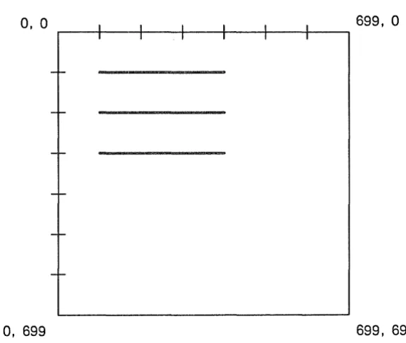
Table 2-4. Advantages and Disadvantages of Frame Mode
Advantages Disadvantages
Easy to use; you take care of the graphics Graphics programs run much slower in calls, and the Display Manager takes care frame mode than in the other modes. of everything else. Frame mode is
There are restrictions on the operations appropriate for simple, noninteractive
applications. you can perform on bitmaps in a frame. Synchronization with other processes is "Player piano" effect: when an image has handled by the Display Manager. had many changes since the last call to
gpr $clear, all such changes are played Reserves an area within a pad for graphics baCK. This playing back, which occurs
display. whenever the window is redrawn for anl
reason, may take a noticeable period 0
Allows you to scroll an image out of view. time to complete. The Display Manager redraws the image
You cannot create true-color graphics in when it is pushed or popped.
frame mode. Allows use of high-level I/O calls such as
READ and WRITE.
[image:26.612.91.550.494.700.2]out-2 .. 3.4 No-Display Mode
When the program selects gpr_$no_display at initialization, the GPR initialization routine allocates a bit-map in main memory. The program can then use GPR routines to perform graphic operations to the main memory bitmap, bypassing any screen display entirely. Applications can use no-display mode to create a main memory bitmap, then call graphics map file routines (GMF calls) to write to a file, or send the bit-map to a peripheral device, such as a printer.
Table 2-5. Advantages and Disadvantages of No-display Mode
Advantages Disadvantages
You can perform graphic operations to Images are not visible on the screen. the bitmap while bypassing the display.
You cannot use the display after
You can create bitmaps larger than the initializing GPR in no-display mode until
screen. you terminate GPR and re-initialize it in
rawin
i
This chapter explains how to draw figures with GPR. You can use GPR to draw lines, arcs, splines, circles, and polygons. This chapter demonstrates the calls shown below:
gpr_$arc_c2p gpr_$arc_3p gpr_$circle gpr _ $ circle _filled gpr _ $cIose _ fill-pgon gpr _ $cIose _return -pgon gpr _ $cIose _return -pgon _ tri gpr_$draw_box
gpr _ $inCL coordinate_origin gpr_$inCLcp
gpr _ $inCL draw -pattern gpr _ $inCL fill-pattern gpr _ $inCLline -pattern gpr _ $inCLlinestyle gpr_$line
gpr_$move gpr $multiline
gpr _ $multitrapezoid gpr _ $multitriangle gpr _ $pgon -polyline gpr _ $polyline gpr _ $rectangle
1
Coordinate System
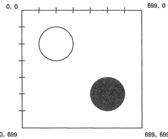
The GPR coordinate system places the coordinate origin at the top left-hand corner of a bitmap. The x values increase to the right, and y values increase downwards. Coordinates for all drawing operations are relative to the coordinate origin. You can change the coordinate origin using the routine gpr_$set_coordi-nate_origin. If you lose track of the coordinate origin, you can call gpr_$in~coordinate_origin. If you initialize a 700 by 700 bitmap, the corners of your bitmap will have the coordinates displayed in Figure 3-1.
0, 0 I I I I I I 699, 0
I I I I I I
f
-
I f I
-
-I-
--0, 699 699, 699
. Figure 3-1. How GPR Views Coordinates
3.1
D1 Current Position
Many drawing routines rely on the coordinates known as the current position; for example, the gpr_$line routine uses the current position as the starting point of a line. After an application program is initialized with gpr_$init, the current position is set to the coordinate origin.
Before calling a routine that depends on the current position, it is often necessary to change the current position. There are two ways to do this. The first is by calling certain GPR routines (e.g., gpr_$line, gpr _ $polyline) which automatically generate a new current position upon completion. The second is by calling the gpr_$move routine which changes the current position without drawing a figure.
3 .. 2 Lines
It is quite simple to draw one or more lines with the GPR package. All you have to do is to initialize the graphics package (with gpr_Sinit) and then call one or more of the following routines:
gpr_Smultiline
Draws a line from the current position to the specified endpoint. The current position is updated to the coordinates of the specified endpoint.
Draws a series of disconnected lines. The current position is updated with each line that is drawn.
Draws a series of connected lines. The current position is updated with each line that is drawn.
3.2.1
Program to Demonstrate gpr_$lIne and gpr_$move
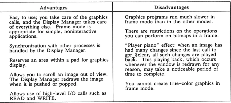
If you run the following program, GPR win display the image shown in Figure 3-2.
Program simple_lines;
{This program demonstrates how to use the gpr_$line call,
and how to change the current position with the gpr_$move call.
}
%include '/sys/ins/base.ins.pas'; %include '/sysjins/gpr.ins.pas';
%include 'my_include_file.pas';{Contains the init, check, and pause routines.}
BEGIN
init(gpr_$borrow);
{Draw a line from the coordinate origin (0,0) to the endpoint (300,300). } gpr_$line(300, 300, status);
{The current position is now set at (300,300). Use the gpr_$move call to change the current position to (100,500). }
gpr_$move(100, 500, status);
{Draw a line from the current position (100,500) to the endpoint (500,500).} gpr_$line(500, 500, status);
{Pause for 5 seconds, then terminate.} pause ( 5 . 0) ;
gpr_$terminate(false, status);
END.
0, 0
0,699
699,0
[image:31.613.166.448.437.678.2]3.2.2
Program
Draw Connected Lines
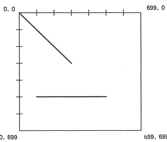
The next program uses the gpr_$polyline call to draw the three connected lines shown in Figure 3-3.
Note that this program could have been written using a gpr_$move and three gpr_$line calls; however, the gpr_$polyline call is usually quicker than a series of gpr_$line calls.
Program connected_lines;
{This program draws several connected lines. It demonstrates the gpr_$polyline call.}
%include '/sys/ins/base.ins.pas'; %include '/sys/ins/gpr.ins.pas';
VAR
array_of_x_coordinates array_of_y_coordinates number_of_end-points
gpr_$coordinate_array_t .- [200, 300, 400]; gpr_$coordinate_array_t .- [300, 400, 200]; integer16 := 3;
%include 'my_include_file.pas';{Contains the init, check, and pause routines.} BEGIN
init(gpr_$borrow);
{Establish the current position at (0,300). If we do not call gpr_$move, the current position will be (O,O).}
gpr_$move(O, 300, status);
{Draw three connected lines. Notice that each endpoint becomes the startpoint for the next line.}
gpr_$polyline(array_of_x_coordinates, array_of_y_coordinates, number_of_end_points, status);
{Pause for 5 seconds, then terminate.} pause(5.0);
gpr_$terminate(false, status);
END.
0,
a
699,a
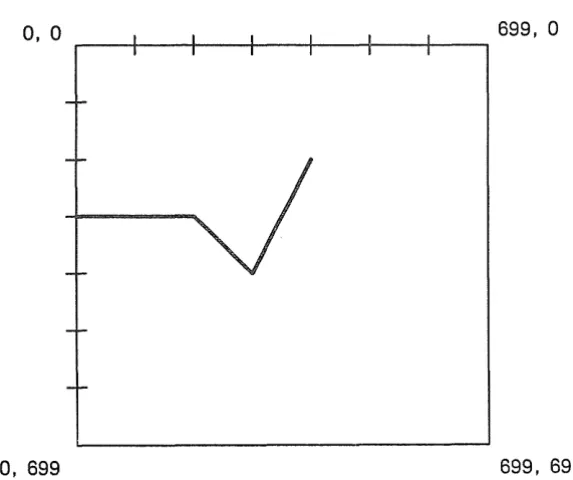
[image:32.615.189.476.463.703.2]3.2.3 A Program to Draw Disconnected Lines
The next program uses gpr_$multiline to draw the three disconnected lines shown in Figure 3-4.
Program disconnected_lines;
{This program draws three disconnected lines. It demonstrates the gpr_$multiline call.
}
%include ~/sys/ins/base.ins.pas~;
%include ~/sys/ins/gpr.ins.pas/;
VAR
array_of_x_coordinates array_of_y_coordinates number_of_points
gpr_$coordinate_array_t :=[100,400,100,400,100,400]; gpr_$coordinate_array_t :=[100,100,200,200,300,300]; integer16 := 6;
%include ~my_include_file.pas~;{Contains the init, check, and pause routines.} BEGIN
init(gpr_$borrow);
{Draw three disconnected lines. Line1 runs from (100,100) to (400, 100); Line2 runs from (100,200) to (400,200); Line3 runs from (100,300) to
(400,300). Notice that we don~t have to use gpr_$move to establish the current position.}
gpr_$multiline(array_of_x_coordinates, array_of_y_coordinates, number_of-points, status);
{Pause for 5 seconds, then terminate.} pause (5.0) ;
gpr_$terminate(false, status); END.
0, 0
0, 699
699,0
[image:33.615.155.443.458.701.2]To draw a circle, use either of the following GPR routines:
gpr _ $circle Draws a circle with a specified radius around a specified center point. This routine does not update the current position.
Draws and fills a circle with a specified radius around a specified center point. The current position is not updated.
The following program draws the two circles shown in Figure 3-5. Program circles_example;
{This program draws two circles. It demonstrates the gpr_$circle and gpr_Scircle_filled calls.}
%include '/sys/ins/base.ins.pas'; %include '/sys/ins/gpr.ins.pas'; VAR
center radius
gpr_Sposition_t;
1 .. 32767;
%include 'my_include_file.pas';{Contains the init, check, and pause routines.} BEGIN
init(gpT_Sborrow); {Draw an unfilled circle.}
center. x_coord .- 200; center.y_coord := 200;
radius := 100;
gpr_Scircle(center, radius, status); {Draw a filled circle.}
center. x_coord .- 400; center.y_coord := 400;
radius := 100;
gpr_$circle_filled(center, radius, status); {Pause for 5 seconds, then terminate.}
pause(5.0);
0, 0 699,0
o
[image:35.615.162.451.73.311.2]0,699 699, 699
Figure 3-5. Using gpr_$circle and gpr_$clrcle_filled to Draw Two Circles
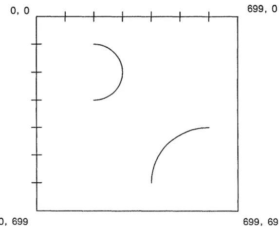
Arcs
An arc is a section of a circle. The section could be as small as one pixel of the circle, or as large as the entire circle. The GPR routines that draw arcs are
Draws an arc from the current position to the point where the arc in-tersects a user-defined line.
Draws an arc from the current position, through two other points. The current position is updated to the coordinates of the second point, which is the last point on the arc.
Program arcs_example;
{This program draws two arcs. It demonstrates the gpr_$arc_c2p and gpr_$arc_3p routines.}
%INCLUDE '/sys/ins/base.ins.pas'; %INCLUDE '/sys/ins/gpr.ins.pas';
VAR
center: gpr_$position_t; p2 : gpr_$position_t;
direction: gpr_$arc_direction_t; option : gpr_$arc_option_t; point2, point3 : gpr_$position_t;
%include 'my_include_file.pas';{Contains the init, check, and pause routines.}
BEGIN
init(gpr_$borrow);
{***Demonstration of gpr_$arc_3p ***}
{The gpr_$arc_3p call draws an arc through any three noncolinear points.
}
The three points are the current position, point2, and point3. The system draws the arc from the current position through point2 and completes the arc at point3.
gpr_$move(200, 200, status);
point2.x_coord := 300; point2.y_coord.- 300; point3.x_coord := 200; point3.y_coord.- 400; gpr_$arc_3p(point2, point3, status);
{set the current position.} {set point2 of the arc.} {set point3 of the arc.} {draw the arc.}
{***Demonstration of gpr_$arc_c2p ***} {The gpr_$arc_c2p call draws an arc between two points.
}
The radius of the arc is the distance from the current position to center. The system starts the arc at the current position and revolves it in a clockwise or counterclockwise direction. The end point of the arc lies on an imaginary ray beginning at center and passing through position p2. The 'option' parameter is only meaningful if the current position
is both the start and end point of the arc. In this case, 'option'
tells the routine whether to draw a full circle or to draw nothing at all.
gpr_$move(600, 400, status); {set the current position.} center. x_coord := 600; center.y_coord .- 600; {set 'center'}
p2.x_coord := 500; p2.y_coord direction := gpr_$arc_ccw;
option := gpr_$arc_draw_full; gpr_$arc_c2p(center, p2, direction, check('drawing arc_c2p');
.- 600; {set 'p2'}
{draw the arc counterclockwise} {ignored in this case.} option, status);
{Pause for 5 seconds, then terminate.} pause(5.0);
0, 0 I I I I I I 699,0
I I I I I I
-r-)
-I-
-r-
-I-
[image:37.617.162.449.75.310.2]--0, 699 699, 699
Figure 3-6. Using gpr_$arc_3p and gpr_$arc_c2p to Draw Two Arcs
3.5 Splines
Splines are curves. You pass a list of points to a spline routine, and the routine uses regression formulas to draw curves that best fit the points. Use the following three routines to generate splines:
gpr_$spline_cubic_p Draws a parametric cubic spline from the current position through a list of control points.
Draws a cubic spline as a function of x from the current position through a list of control points.
Draws a cubic spline as a function of y from the current position through a list of control points.
After completing any of these calls, the system updates the current position to the coordinates of the last control point.
The following program draws a spline:
Program spline_example;
{This program draws a cubic spline as a function of x. It demonstrates the gpr_$spline_cubic_x routine.
}
%include ~jsysjinsjbase.ins.pas~;
%include 'jsysjinsjgpr.ins.pas';
VAR
BEGIN
init(gpr_$borrow);
{Draw spline as a function of x. Starting position of spline will be the current position of [0,0] }
gpr_$spline_cubic_x(array_of_x~ts, array_of_y~ts, npoints, status); check('drawing spline');
{Pause for 5 seconds, then terminate.} pause (5.0) ;
gpr_$terminate(false, status);
END.
Polygons
A filled polygon is a closed figure having three or more sides whose interior is partially or totally drawn covered You can use the following routines to generate filled polygons:
gpr _ $rectangle
gpr _ $muititrapezoid gpr _$ m uititriangles
gpr _ $dose _ fill_pgon gpr _ $dose _return _pgon
Draws and fills a rectangle. Dra ws and fills a triangle. Draws and fills a trapezoid.
Draws and fills one or more trapezoids. Draws and fills one or more triangles. Defines the starting position of a polygon.
Defines a series of line segments forming part of a polygon bound-ary.
Closes and fills the currently open polygon.
Closes the currently open polygon (without filling it) and returns the list of trapezoids within its interi~r.
Closes the currently open polygon (without filling it) and returns the list of triangles within its interior.
The way that GPR fills a polygon depends on the values of the following attributes:
• Current fill value (described later in this chapter and in Chapter 6). • Background fill value (described later in this chapter).
• Raster operation (described in Chapter 11). • Tile pattern (described in Section 3.6.1.).
Program triangle_rectangle_trapezoid;
{This program draws a triangle, rectangle, and trapezoid. It demonstrates the gpr_$triangle, gpr_$rectangle, and gpr_$trapezoid calls.
}
%include //sys/ins/base.ins.pas/; %include '/sys/ins/gpr.ins.pas';
VAR
triangle_vertex1, triangle_vertex2, triangle_vertex3 gpr_$position_t; rectangle: gpr_$window_t;
trapezoid: gpr_$trap_t;
%include /my_include_file.pas';{Contains the init, check, and pause routines.~ BEGIN
init(gpr_$borrow);
{Draw a filled triangle.}
triangle_vertex1.x_coord .- 100; triangle_vertexl.y_coord.- 100; triangle_vertex2.x_coord .- 300; triangle_vertex2.y_coord.- 100; triangle_vertex3.x_coord .- 200; triangle_vertex3.y_coord.- 200;
gpr_$triangle(triangle_vertex1, triangle_vertex2, triangle_vertex3,status);
{Draw a filled rectangle.}
r~ctangle.window_base.x_coord := 100; rectangle.window_base.y_coord .- 300; rectangle. window_size. x_size := 200; rectangle.window_size.y_size .- 300; gpr_$rectangle(rectangle, status);
{Draw a filled trapezoid. In aPR, a trapezoid is with parallel bottom and top sides.}
trapezoid.top.x_coord_l
.-
300; {x trapezoid.top.x_coord_r.-
500; {x trapezoid.top.y_coord.-
200; {y trapezoid.bot.x_coord_l.-
400; {xtrapezoid.bot.x_coord_r
.-
650; {xtrapezoid. bot. y_coord
.-
500; {y gpr_$trapezoid(trapezoid, status);{Pause for 5 seconds, then terminate.} pause(5);
gpr_$terminate(false, status);
END.
coordinate coordinate coordinate coordinate coordinate coordinate
a four-sided polygon
0, 0
r----r----r----+----+----+----~--~ 699,0
[image:40.615.192.474.74.316.2]0,699 699, 699
Figure 3-7. Using gpr _ $ triangle I gpr _ $rectangle I and gpr _ $ trapezoid
The polygon routines open and define the boundaries of a polygon, and either close and fill the polygon immediately, or close the polygon and return its decomposition to the program for later drawing and fill-ing. The routine gpr_$pgonyolyline does not draw a polygon; the routine defines a series of line segments for decomposition for filling operations.
A polygon's boundary consists of one or more closed loops of edges. The polygon routine gpr_$startygon establishes the starting point for a new loop, closing off the old loop if necessary. The polygon routine gpr _ $pgon yolyline defines a series of edges in the current loop.
The polygon routines gpr_$close_fillygon, gpr_$close_returnygon, and gpr_$close_returnygon_tri close a polygon by decomposing it. See Appendix E for a discussion of decomposition techniques. The polygon routines define the interior of a polygon to be all points from which a line can originate and cross the polygon boundary an odd number of times.
Program polygons;
{The program draws a five-sided polygon. It demonstrates the gpr_$start-pgon, gpr_$pgon-polyline, and gpr_$close_fill-pgon routines.
}
%include 'jsysjinsjbase.ins.pas'; %include 'jsysjinsjgpr.ins.pas';
VAR
array_of_x_coords : gpr_$coordinate_array_t .- [100,600,600,350]; array_of_y_coords : gpr_$coordinate_array_t .- [600,600,300,100]; number_of_points_in_array : integer16 := 4;
%include 'my_include_file.pas';{Contains the init, check, and pause routines.}
BEGIN
init(gpr_$borrow);
{Set the starting point of the polygon.} gpr_$start_pgon(100, 300, status);
{Set the other four points of the polygon.}
gpr_$pgon_polyline(array_of_x_coords, array_of_y_coords, number_of-points_in_array, status); check('calling pgon_polyline');
{Connect the five points and fill it with the current fill color.} gpr_$close_fill_pgon(status);
check('calling close_fill-pgon');
{Pause for 5 seconds, then terminate.} pause (5.0) ;
gpr_$terminate(false, status);
END.
a, a
0, 699
699,
a
699, 699
3 .. 6 .. 1 Creating a Tile Pattern
GPR fills circles, rectangles, triangles, trapezoids, and triangles with the current tile pattern. By default, the tile pattern is solid, meaning that every pixel within the borders of the image is filled with the same color. However, you can create a nondefault tile pattern. In the following sections, we explain the method for creating a tile pattern on a monochromatic node and the two methods for creating a tile pat-tern on color nodes.
Tile Patterns on Monochromatic Nodes
To create a nondefault tile pattern on a monochromatic node, follow these steps:
1. Allocate a 32x32 bitmap to store the tile pattern. (Chapter 5 explains how to allocate bitmaps.) 2. Make this bitmap current and generate a pattern of l's and O's in it. You might, for example, use a combination of gpr _ $move and gpr _ $line commands to create a dotted or lined tile pattern. 3. Make the display bitmap current.
4. Call the gpr_$set_fillJJattern routine to specify that your 32x32 bitmap contains the tile pattern. After establishing a tile pattern, you merely have to call one of the fill routines (e.g., gpr_$circle_filled), and the system will fill the figure using the nondefault tile pattern.
Tile Patterns on Color Nodes -- Method 1
In method 1 for creating a nondefault tile pattern on a color node, you follow the same four steps de-scribed for creating a tile pattern on a monochromatic nodes. Note that you must specify a 32x32xl bit-map; that is, the bitmap you allocate should have only 1 plane (hiJJlane = 0). In addition to steps 1 through 4, you will probably also want to follow two additional steps:
5. Call gpr_$set_fill_value. At runtime, every bit with a value of" 1" will actually be painted with the given fill value color.
6. Call gpr_$set_fill_background_value. At runtime, every bit with a value of "0" will actually be painted with the given fill background value color.
Program tile-pattern;
{This program creates a nondefault tile pattern. It demonstrates the gpr_$set_fill_value, gpr_$set_fill_background_value, and
gpr_$set_fill-pattern routines. You must run this program on a color node.} %include '/sys/ins/base.ins.pas';
%include '/sys/ins/gpr.ins.pas'; CaNST
fill_value = 3;
background_value = 5; VAR
center gpr_$position_t.-radius integer16:= 300; x, y integer16;
scale integer16:= 1;
[300, 300];
size_of_tile_pattern
attribute_block_descriptor bitmap_desc_of_tile-pattern hi-plane_of_mmb
gpr_$offset_t := [32,32]; gpr_$attribute_desc_t; gpr_$bitmap_desc_t; gpr_$rgb_plane_t := 0;
%include 'my_include_file.pas';{Contains the init, check, and pause routines.} BEGIN
init(gpr_$borrow);
{Generate a 32x32 main memory bitmap to hold the tile pattern. It is essential that the hi_plane value be O. If it is not 0, then the calls to set the fill value and fill background value will have no effect.}
gpr_$allocate_attribute_block(attribute_block_descriptor, status); gpr_$allocate_bitmap(size_of_tile_pattern, hi-plane_of_mmb,
attribute_block_descriptor,
bitmap_desc_of_tile-pattern, status); gpr_$set_bitmap(bitmap_desc_of_tile-pattern, status);
{Set every 16th bit in the bitmap.} for x := 0 to 31 do begin
for y := 0 to 31 do begin
if «x MOD 4 = 0) AND (y MOD 4 gpr_$move(x, y, status); gpr_$line(x, y, status); end;
end; end;
0» then begin
{Make the display bitmap current and then set 3 attributes in its attribute block. Every 16th bit will be painted with the fill value; the other 15 bits will be painted with the background fill value.}
gpr_$set_bitmap (display_bitmap , status); gpr_$set_fill_value(fill_value, status);
gpr_$set_fill_background_value (background_value , status);
gpr_$set_fill-pattern(bitmap_desc_of_tile-pattern, scale, status);
{Draw a filled circle using the current tile pattern.} gp~_$circle_filled(center, radius, status);
{Pause for 5 seconds, then terminate.} pause ( 5 . 0) ;