DEVELOPMENT OF CONCEPTUAL AUTOMATIC CAR JACK DESIGN USING TOTAL DESIGN APPROACH
SITI NAJIAH BINTI ROSMINAHAR
B051110230
UNIVERSITI TEKNIKAL MALAYSIA MELAKA
UNIVERSITI TEKNIKAL MALAYSIA MELAKA
DEVELOPMENT OF CONCEPTUAL AUTOMATIC CAR JACK
DESIGN USING TOTAL DESIGN APPROACH
This report submitted in accordance with requirement of the Universiti Teknikal Malaysia Melaka (UTeM) for the Bachelor Degree of Manufacturing Engineering
(Design Engineering)(Hons.)
by
SITI NAJIAH BINTI ROSMINAHAR
B051110230
900914-06-5470
UNIVERSITI TEKNIKAL MALAYSIA MELAKA
BORANG PENGESAHAN STATUS LAPORAN PROJEK SARJANA MUDA
TAJUK: INVESTIGATION OF FACTORS CAUSING MEASUREMENT ERROR USING GAGE R&R METHOD FOR ENHANCING MEASUREMENT CAPABILITY IN SMALL MEDIUM INDUSTRIES (SMI)
SESI PENGAJIAN: 2013/14 Semester2
Saya SITI NAJIAH BINTI ROSMINAHAR
Mengaku membenarkanLaporan PSM ini disimpan di Perpustakaan Universiti Teknikal Malaysia Melaka (UTeM) dengansyarat-syaratkegunaansepertiberikut:
1. Laporan PSM adalah hak milik Universiti Teknikal Malaysia Melaka dan penulis. 2. Perpustakaan Universiti Teknikal Malaysia Melaka dibenarkan membuat salinan
untuk tujuan pengajian sahaja dengan izin penulis.
3. Perpustakaan dibenarkan membuat salinan laporan PSM ini sebagai bahan pertukaran antara institusi pengajian tinggi.
4. **Silatandakan ( )
SULIT
TERHAD
TIDAK TERHAD
(Mengandungimaklumat yang
berdarjahkeselamatanataukepentingan
Malaysiasebagaimana yang termaktubdalamAKTA RAHSIA RASMI 1972)
(Mengandungimaklumat TERHAD yang telahditentukanolehorganisasi/badan di manapenyelidikandijalankan)
AlamatTetap:
27,LRG PMTG BADAK BARU 19, BUKIT RANGIN, 25150
Tarikh: ________________________
Disahkanoleh:
Cop Rasmi:
Tarikh: _______________________
DECLARATION
I hereby, declared this report entitled “Development of Conceptual Automatic Car Jack Design using Total Design Approach” is the results of my own research
except as cited in references.
Signature : ……….
Author’s Name : Siti Najiah Bt Rosminahar
APPROVAL
This report is submitted to the Faculty of Manufacturing Engineering of UTeM as a partial fulfillment of the requirements for the degree of Bachelor of Manufacturing Engineering (Design Engineering) (Hons.). The member of the supervisory is as follow:
ACKNOWLEDGEMENT
In the name of Allah, the Most Gracious, the Most Merciful. Praise to the Almighty that I have been given strength and with His will, I am able to complete PSM 1 project.
i
ABSTRAK
Bicu adalah peralatan yang digunakan untuk mengangkat beban yang berat atau memberi tekanan yang tinggi. Bicu menggunakan bebenang skru atau silinder hidraulik yang memberi tekanan linear yang tinggi. Antara bicu yang diguna pakai kebanyakan pemandu adalah bicu yang menggunakan skru untuk berfungsi. Pengguna menghadapi kesulitan dalam menggunakan bicu yang sedia ada kerana masalah ergonomik. Tujuan utama pengubahsuaian adalah kerana masalah sakit belakang yang dihadapi pengguna berikutan kedudukan mencangkung dan membongkokkan badan terlalu lama ketika proses penukaran tayar. Dengan adanya teknologi yang maju, bicu automatik boleh direka bagi membantu mengurangkan masalah lenguh badan atau sakit belakang yang membawa kepada masalah kesihatan yang lain. Konsep bagi bicu kereta automatik boleh dibangunkan dengan menggunakan konsep ‘Total Design Approach’ iaitu konsep reka bentuk secara total dengan mengaplikasikan kaedah Pugh. Proses pembangunan produk ini berkait rapat dengan keperluan pasaran, spesifikasi produk, konsep rekaan dan rekaan yang terperinci yang melengkapi satu sama lain. Projek ini menggunakan Total Design
Approach bagi memperolehi rekabentuk akhir bagi rekaan konsep bicu. Analisa dari
ii
ABSTRACT
iii
DEDICATION
iv
ACKNOWLEDGEMENT
In the name of Allah, the Most Gracious, the Most Merciful. Praise to the Almighty that I have been given strength and with His will, I am able to complete PSM 1 project.
v
TABLE OF CONTENT
Abstrak Abstract Dedication
Acknowledgement Table of Contents List of Tables List of Figures
List of Abbreviations, Symbols and Nomenclatures
i ii iii iv v x xi xii
CHAPTER 1: INTRODUCTION 1
1.1 Background Study 1-2
1.2 Problem Statement 2
1.3 Objective 3
1.4 Scope of Project 3
CHAPTER 2: LITERATURE REVIEW 4
2.1 Introduction 4
2.2 Existing Car Jack 5-6
2.3 Design Method 6
2.4 Total Design 6
2.5 Engineering Design 7
2.6 Advantage and Disadvantage of Total Design 7
vi
2.7.1 Pahl and Beitz’ model 8-9
2.7.2 Pugh’s Model 10-11
2.7.3 French’s model 12-13
2.7.4 Cross’s Method 13
2.7.5 Otto and Wood in Product Design 14-15
2.7.6 Ulrich and Eppinger Product Design Development 16
2.7.7 Comparison of Design Method 16-18
2.8 Problem Solving Tool 19
2.8.1 Quality Function Deployment 19
2.8.1.1. Voice of Customer (VOC) 20
2.8.2 Theory of Inventive Problem Solving (TRIZ) 20
2.8.3 Brainstorming 20
2.9 Finite Element Analysis (FEA) 21-22
2.9.1 Definition of FEA and Type of Engineering Analysis 21 2.9.2 Application of FEA and Working Principle 22
2.10 Summary 22
CHAPTER 3:METHODOLOGY 23
3.1 Introduction 23
3.2 Flow chart Methodology 23-24
3.3 Identify Objective and Problem Statement 25
3.4 Research and literature review 25
3.5 Application of Pugh’s method for Automatic Car Jack Development 25
3.5.1 Market Identification 25-26
vii
3.5.3 Conceptual Design 28
3.5.3.1 Concept Generation 28
3.5.3.2 Concept Evaluation 28-29
3.5.3.3 Concept Development 29
3.5.4 Detail Design 29
3.5.3.3 Detail drawing 29
3.5.4.2 Bill of Material (BOM) 30 3.6 Product Design and generate 3D modelling of new design 30
3.7 Analysis and Results 30
3.7.2 Finite Element Analysis (FEA) 30
3.8 Discussion 31
3.9 Conclusion 31
CHAPTER 4:DEVELOPMENT OF CONCEPTUAL CAR JACK 32
4.1 Market Identification 32
4.2 Product Design Specification (PDS) 32-33
4.3 Conceptual Design Stage 34
4.3.1 Concept Generation 34
4.4 Concept Evaluation 34
4.4.1 Decision Option 34
4.4.1.1 Concept A 35
4.4.1.2 Concept B 36
4.4.1.3 Concept C 37
4.5 Concept Selection 38
viii
4.6 Concept Development
4.7 Final Design
41 43
CHAPTER 5:RESULT AND DISCUSSION 44
5.1 Introduction 44
5.2 Finite Element Analysis (FEA) by using SolidWorks Simulation 45
5.3 Result 45
5.3.1 Analysis of Design Concept A (DC-A) 45-46
5.3.2 Material for Automatic Screw Car Jack 46-48
5.3.3 Load and Fixtures 48-50
5.3.4 Resultant Force 50-51
5.3.5 Stress 51-52
5.3.6 Resultant Displacement of Car Jack 52-53
5.3.7 Strain 53
5.4 Discussion 54
5.4.1 Component of DC-A
5.4.2 Pugh’s Concept Selection Method
54 55-56 5.4.3 Comparison Result between Design Concept 57 5.4.4 Finite Element Analysis (FEA) for Part Involves
5.4.4.1 Upper Part of Car Jack 58
CHAPTER 6:CONCLUSION AND RECOMMENDATION 59
5.5 Conclusion 59
5.6 Recommendation 59
ix
APPENDICES
x
LIST OF TABLES
2.1 Comparison of Design Method 17-18
3.1 PDS Document Checklist 29-29
3.2 Pugh’s Concept Selection Method 30
4.1 Results of Selection 39
4.2 Evaluation Chart for Conceptual Automatic Car Jack 40 5.1 Properties of Low Alloy Steel and Aluminium Alloy 47
5.2 Reaction Forces 50
5.3 Reaction Moment 51
5.4 Von Mises Stress 52
xi
LIST OF FIGURES
2.1 Screw Car Jack (Source:Harbour Freight Tools) 5
2.2 Various model of lead screw (Source: Designatronics Inc.) 6
2.3 Pahl and Beitz’s design Model 9 2.4 Pugh model of the design process (Source: Pugh, 1986) 11
2.5 French model of the design process 12
2.6 Cross Design Method 13
2.7 Reverse engineering and redesign methodology 15
2.8 Ulrich and Eppinger’s Design Methodology 16
2.9 Structured part is analysed using FEA 21
3.1 Flow Chart Methodology 24
4.2 Concept A 36
4.3 Concept B 37
4.4 Concept C 38
4.5 Automatic Car Jack Development 42
4.6 Final Design 43
5.1 Original Model of Car Jack and part of Car Jack analysed 46
5.2 Ashby’s Chart of Toughness versus Strength 47
5.3 Extract images of result from FEA analysis for Fixture 49
xii
5.5 Force act upon the plane as load is lowered and lifted 50
5.6 Von Mises Stress of car jack 51
5.7 Displacement of car jack 52
5.8 Strain analysis of Car Jack 53
5.9 Drawing of Car Jack 54
xiii
LIST OF ABBREVIATIONS, SYMBOLS AND
NOMENCLATURE
CAD - Computer Aided Design
FEA - Finite Element Analysis
PDP - Product Development Process
BOM - Bill of Material
DFE - Design for Environment
1
This chapter provides background, problem statement, objective as well as scope of the study.
1.1 Background Study
A jack is a mechanical device used as a lifting device to lift heavy loads or apply great forces. Jacks employ a screw thread or hydraulic cylinder to apply very high linear forces. The Longman Dictionary defines a jack as a piece of equipment which is used to lift and support a heavy weight, such as a car. The most common car jack used is screw car jack. A screw jack uses a simple theory of gears to get its power. As the screw section is turned, two ends of the jack move closer together. Because the gears of the screw are pushing up the arms, the amount of force being applied is multiplied. It takes a very small amount of force to turn the crank handle, yet that action causes the brace arms to slide across and together. As this happens the arms extend upward. The car's gravitational weight is not enough to prevent the jack from opening or to stop the screw from turning, since it is not applying force directly to it (Smith, 2010).
Screw car jack is the simplest design among its class. By adding automatic value on this car jack, a new car jack is designed. The Merriam-Webster online dictionary defines automatic as having controls that allow something to work or happen without being directly controlled by a person. The current design of automatic car jack add component as motor that generate power to lift up the car. A mechanical jack is a device which lifts heavy equipment and vehicles so that maintenance can be carried out underneath (Budynas, and Nisbett, 2008). In terms of ergonomic prospect, doing
INTRODUCTION
2
work in a bent or squatting position for a period of time is not ergonomic to human body. It gives back ache problem in due of time. This requires new modification for the mechanical car jack. Automatic car jack may consist of motorised screw by connecting it to the motor that help to regulate the lifting and lowering process. The new ideas of conceptual automatic car jack design require some serious design works. This can be achieved through several designing method such as Total Design approach. Total design concept consist of three elements (1) functionality, which arises from the product’s features and related benefits for customers, (2) aesthetics, comprising the product's sensorial characteristics, including, its appearance, touch, smell, taste and sound, and (3) meaning, involving the associations of the product in the minds of its customers (Srinivasan et al., 2008). Total Design is a systematic methodology to achieve integration of the technological as well as nontechnological subject material with the goal of creating successful products and processes (Pugh, 1990).
By designing the new car jack design that emphasize more on the conceptual automatic car jack, this study will be deployed on the development of conceptual automatic car jack using total design approach.
1.1 Problem statement
3
operational structure is constructed thus help in product design integration where market need, product specification, concept design, and detail design act in accordance with each other (Pugh, 1990).
1.2 Objectives of study
The aim of this study is to design a new conceptual automatic car jack using total design approach. The specific objectives for this project are listed as below:
a) To design car jack that is safe, reliable and are able to be raised and lowered in height level.
b) To use engineering decision-making approach for developing conceptual automatic car jack.
c) To develop a car jack powered by internal car power and fully automated using limit switch.
1.3 Scope of Project
4
A review on previous research work in several areas relevant to this research is presented in this chapter.
2.1 Introduction
Product development process (PDP) are the procedures and methods used by companies use to design new products and sell to the market (Unger and Eppinger, 2009). A product development process is the sequence steps of activities that an enterprise employs to conceive, design, and commercialize a product (Ulrich, 2012). Acknowledgement of process development is relatively new because a traditional, staged process dominated US industry for almost 30 years (Smith and Reinersten 1992, McConnell, 1996). Through the development of various PDP model prepare many choices for the companies as they changed from staged process to speed the design process and reduce costs (Lim et al., 2006). Studies suggest that technical innovation accounts for more than 80% of long term economic improvement (Solow, 1957). By applying engineering design practice can result in valuable progress. This chapter covers on design method by Pugh, Pahl and Beitz, Cross, Ulrich and Eppinger, Otto and Wood and French. It also covers advantage and disadvantages of total design, comparison of design method and existing car jack review.
LITERATURE REVIEW
5
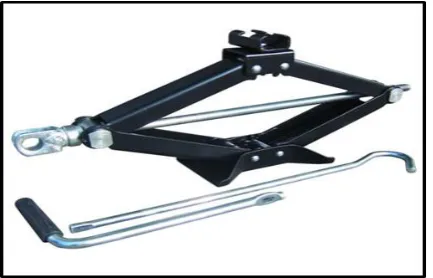
2.2 Existing Car Jack
[image:24.595.212.429.175.314.2]There are two most common used car jacks in market nowadays, hydraulic car jack and screw car jack. A jackscrew as shown in Figure 2.1 is a type of jack operated just by turning the lead screw.
Figure 2.1: Screw car jack (Source: Harbour Freight Tools,2014)
[image:24.595.197.442.601.734.2]A small force amount of force is applied in the horizontal plane that is used to raise lower large load (Khurmi and Gupta, 2005). Screw jacks designed to be able to withstand both tensile and compressive force. Mechanism of screw jack consists of lead screw and mating nut. Lead screw applies tension force for the screw jack to obtain compressive force. For this reason, usually an acme thread is used. This thread is very strong as it can resist the large loads enforced by car which is approximately 1000N and not weakened by wear over many rotations made when operating. Its larger thread contact area enables the load capacity to be much higher and higher friction prevent back-driving. In addition, the mating nut helps to tighten the engagement of the screw and not allowing backlash to develop (Rajput, 2007). Figure 2.1 shows various model of lead screw available in the market.