This is a repository copy of
Performance of superconducting generators with different
topologies under fault conditions
.
White Rose Research Online URL for this paper:
http://eprints.whiterose.ac.uk/129970/
Version: Published Version
Proceedings Paper:
Guan, Y., Vedreño-Santos, F., Azar, Z. et al. (4 more authors) (2019) Performance of
superconducting generators with different topologies under fault conditions. In: The Journal
of Engineering. The 9th International Conference on Power Electronics, Machines and
Drives (PEMD 2018), 17-19 Apr 2018, Liverpool, UK. IET , pp. 4090-4095.
https://doi.org/10.1049/joe.2018.8183
[email protected]
https://eprints.whiterose.ac.uk/
Reuse
This article is distributed under the terms of the Creative Commons Attribution (CC BY) licence. This licence
allows you to distribute, remix, tweak, and build upon the work, even commercially, as long as you credit the
authors for the original work. More information and the full terms of the licence here:
https://creativecommons.org/licenses/
Takedown
If you consider content in White Rose Research Online to be in breach of UK law, please notify us by
The Journal of Engineering
The 9th International Conference on Power Electronics, Machines and
Drives (PEMD 2018)
Performance of superconducting generators
with different topologies under fault
conditions
eISSN 2051-3305
Received on 25th June 2018 Accepted on 30th July 2018 E-First on 31st May 2019 doi: 10.1049/joe.2018.8183 www.ietdl.org
Yang Guan
1,2, Francisco Vedreño-Santos
1,2, Ziad Azar
1,2, Arwyn S. Thomas
1,2, Guang-Jin Li
1,2, Milijana
Odavic
1,2, Zi-Qiang Zhu
1,21Sheffield Siemens Wind Power Research Centre, Sheffield, UK 2The University of Sheffield, UK
E-mail: [email protected]
Abstract: This paper compares the short-circuit performance of superconducting (SC) generators with three different topologies, i.e. iron-cored stator and rotor, iron-cored stator and air-cored rotor, and air-cored stator and rotor. The analysis is based on three-phase short-circuit fault, and finite element analysis is used for simulation. Following the introduction of specifications of generators, the short-circuit performances of different topologies are analysed and compared, with the field winding excited by voltage and current excitation sources, respectively. It shows that the short-circuit performance can be improved by limiting the field current.
1 Introduction
Due to high power density of superconducting (SC) synchronous generators, they are being considered for marine applications and wind turbines, which have tough requirements for the size and weight of the machine.
For the design of SC generators, much attention has to be paid to the performances under different types of fault conditions, although they are rare and short-lasting. The SC generators need to be designed carefully to withstand these faults. Usually, the three-phase short-circuit is considered to be most stressful [1]. The transient responses induced by the three-phase short-circuit fault include:
i. The current in the armature winding is significantly increased, and large forces are produced in the armature winding. The force on the end winding is especially harmful, due to lack of supporting structures [1].
ii. The electromagnetic torque is highly increased, sometimes with peak torque as high as almost 10 times of rated torque [2], which imposes a large stress on the mechanical design of generators.
iii. The current in the field winding is increased. Such a current increase is not a problem for conventional electrically excited generators [1]. However, it is especially harmful for SC generators. If the increased field current is beyond the critical current of SC material and lasts for a while, the SC material may be quenched [3]. In addition, such a current increase can produce a high force on the field winding, which further deteriorates the performances of SC material and makes it more vulnerable to quenching and even damaging.
In order to withstand the large peak fault torque, more material has to be used to improve the mechanical performance of some components, such as the support for SC coils and torque tube etc., which leads to the increase of total weight. The quantity of SC material can be increased to improve the safety margin to ride through the large fault field current. However, it is not economically feasible, due to the high cost of SC material nowadays [2]. Usually, the transient current increase in the armature and field windings should be interrupted rapidly. It can be realised by adding some protections, such as breakers and current limiters etc. to the system [4, 5].
The analysis of short-circuit performance is usually based on some kind of topology, and the field winding is excited by a voltage excitation source. The current-limiting equipment is usually added to the stator side to protect the machine [1–7]. Here, the short-circuit performances of SC generators with different topologies and different types of excitation sources are analysed. The paper is organised as follows. In Section 2, the structures, specifications, and modelling method of three different SC generator topologies are described. Their short-circuit performances are compared in Sections 3 and 4, with the field winding excited by voltage and current sources, respectively. It shows that the short-circuit performance can be improved by imposing current-limiting strategies on the field winding.
2 Structure, specification, and modelling of
generator
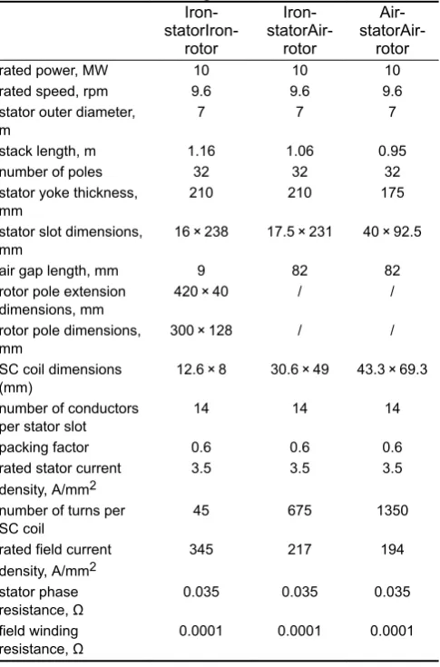
The investigated topologies include iron-cored stator and rotor, iron-cored stator and air-cored rotor, and air-cored stator and rotor. They are optimised, respectively, according to the specification of 10 MW offshore direct-drive wind turbine. The optimisation process can be found in [8]. The cross-sections are shown in Fig. 1. The major specifications of the three SC generators are listed in Table 1.
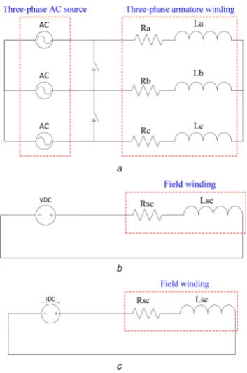
The generator is modelled by the finite element analysis software MAXWELL. The connections of armature and field windings with voltage and current excitation sources are shown in Fig. 2. Before the short-circuit fault arises, the generator operates at rated condition, with rated three-phase currents imposed on the armature winding and the switches are off. At 0.43 s, the switches are turned on to simulate a symmetrical three-phase short-circuit fault. In the simulation, the rotor speed is assumed to be fixed at 9.6 rpm in order to simplify the modelling. In real case, it varies with time, which is not only related with the generator, but also with the blades and associated speed-governing system. The modelling for the whole system is difficult. However, since the inertia of the whole system is quite large for a direct-drive wind turbine and the fault usually endures for quite a short time, it is reasonable to assume that the speed does not change.
3 Results with voltage excitation source
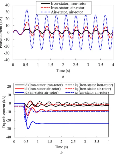
3.1 Phase currentThe response of phase current is shown in Fig. 3. The amplitude of phase current of air-cored stator and rotor topology is much larger than that of iron-cored stator topology. It can be explained according to (1).
ia= 2E0
Xd (1)
where ia is the amplitude of phase steady current, E0 is the phase
electromotive force (EMF), xd is the d-axis impedance. For air-cored stator and rotor topology, the stator teeth and rotor poles are made of some kind of material with permeability the same as vacuum. Thus, the d-axis inductance is the smallest and ia is the largest. The peak phase currents for iron-cored stator and rotor, iron-cored stator and air-cored rotor, and air-cored stator and rotor topologies are 5.4, 5.5 and 13 times of rated values, respectively.
The dq-axes currents are shown in Fig. 3b. The d-axis is aligned with the rotor field direction. It can be seen that the stator current is mainly for demagnetisation of field winding, since d-axis current is much larger than q-axis current, and the direction is opposite to that of excitation field.
3.2 Torque
The variation of torque with time is shown in Fig. 4. The peak and steady torque of air-cored stator and rotor topology are much larger than that of iron-cored stator topology. When a three-phase short-circuit fault arises, the torque-produced power is only consumed inside the machine on the copper loss. For air-cored stator and rotor topology, the short-circuit phase current is the largest, as shown in Fig. 3a, and thus, the copper loss is the highest. Consequently, the fault torque is the highest. It can be seen that the steady fault torque is even larger than the rated torque for air-cored stator and rotor topology.
Fig. 1 Flux lines at different time
[image:3.595.180.412.50.340.2](a) Time = 0, iron-cored stator and rotor topology, (b) Time = 0.5859 s (at this time, the fault force reaches the peak value), iron-cored stator and rotor topology, (c) Time = 0, iron-cored stator and air-iron-cored rotor topology, (d) Time = 0.5859, iron-cored stator and air-cored rotor topology, (e) Time = 0, air-cored stator and rotor topology, (f) Time = 0.5859, air-cored stator and rotor topology
Table 1 Parameters of SC generator Iron- statorIron-rotor Iron- statorAir-rotor Air- statorAir-rotor
rated power, MW 10 10 10
rated speed, rpm 9.6 9.6 9.6
stator outer diameter,
m 7 7 7
stack length, m 1.16 1.06 0.95
number of poles 32 32 32
stator yoke thickness,
mm 210 210 175
stator slot dimensions,
mm 16 × 238 17.5 × 231 40 × 92.5
air gap length, mm 9 82 82
rotor pole extension
dimensions, mm 420 × 40 / /
rotor pole dimensions,
mm 300 × 128 / /
SC coil dimensions
(mm) 12.6 × 8 30.6 × 49 43.3 × 69.3 number of conductors
per stator slot 14 14 14
packing factor 0.6 0.6 0.6
rated stator current
density, A/mm2 3.5 3.5 3.5
number of turns per
SC coil 45 675 1350
rated field current density, A/mm2
345 217 194
stator phase
resistance, 0.035 0.035 0.035
field winding
resistance, 0.0001 0.0001 0.0001
[image:3.595.44.287.404.772.2]3.3 Field current
The variations of field current and flux linkage are shown in Fig. 5.
During the period of short-circuit fault, the field winding flux is always constant, as shown in Fig. 5b, which can be explained according to (2).
dψ
dt +Ri=u (2)
where , R, i, and u are the rotor flux linkage, resistance, current, and voltage, respectively. For the SC field winding, Ri can be removed. Consequently, is constant due to the constant voltage source. In order to keep a constant flux linkage, a larger short-circuit steady-state field current is required to eradicate the influence of increased stator d-axis current. For iron-cored stator and rotor topology, the mutual inductance between stator and rotor is the largest, and thus, the influence of stator current on rotor field winding is the strongest. Consequently, the increases of field current are more significant than that of other two topologies. The peak field currents for iron-cored stator and rotor, iron-cored stator air-cored rotor, and air-cored stator and rotor topologies are 5.4, 1.4, and 1.4 times of rated values, respectively. The design of SC field winding for iron-cored stator and rotor topology is more challenging, due to the higher short-circuit current, which can easily quench the SC material.
3.4 Force on rotor component
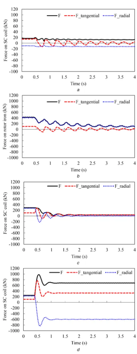
The rotor force calculation is carried out for a fractional part of the whole generator (1/16 of the whole generator), involving one SC coil and one rotor iron pole. The flux lines for different topologies operating at rated and short-circuit conditions are shown in Fig. 1.
The forces are shown in Fig. 6. For iron-cored stator and rotor topology, when it operates at rated condition, most of the flux lines go through the rotor iron. Consequently, most of the force is acting Fig. 2 Connections of armature and field windings
(a) Armature winding, (b) Field winding with voltage source, (c) Field winding with current source
Fig. 3 Variations of stator
(a) Phase and, (b)dq-axis currents
Fig. 4 Variation of torque with time
Fig. 5 Variations of field
(a) Current and, (b) Flux linkage with time
[image:4.595.82.259.46.313.2] [image:4.595.318.540.84.487.2] [image:4.595.50.277.355.652.2]on the rotor iron, and the force on SC coil is negligibly small, compared with that of air-cored rotor topology. When the short-circuit fault arises, more flux lines will go out of the rotor iron and through the SC coil, Figs. 1a and b, due to more saturated rotor iron. Thus, the influence of armature current on the SC coil is increased. Consequently, the peak fault force on SC coil of iron-cored stator and rotor topology increases significantly, ∼20 times
of rated torque, due to the increase of both field current, Fig. 5a, and influence of armature current. However, the force on rotor iron increases little, because the rotor iron is already quite saturated under rated operation.
The force on SC coil of iron-cored stator and air-cored rotor topology increases a little, 1.4 times of rated value, because the increase of field current is not significant, Fig. 5a. The peak fault torque for air-cored stator and rotor topology is the largest, 6.4 times of rated value, due to the significant increase of armature current, Fig. 3.
Overall, the peak fault torque on SC coils of air-cored stator and rotor topology is the largest, about 3–4 times of that of iron-cored stator topology. Consequently, the design of SC coil and corresponding supporting structure is more challenging.
4 Results with current excitation source
The responses of stator current, torque, field current, and flux linkage, and forces on rotor components of the three topologies with current excitation sources are shown in Figs. 7–10. Similar conclusions can be drawn for the comparison of different topologies as obtained in Section 3. The air-cored stator and rotor topology has the poorest short-circuit performances, in terms of stator current, torque, and forces on SC coil. For the air-cored stator and rotor topology excited with voltage excitation source, the increase of fault current of SC coil is the smallest. However, in this section, the currents of SC coils for different topologies are all constant, due to the limitation of current excitation source.
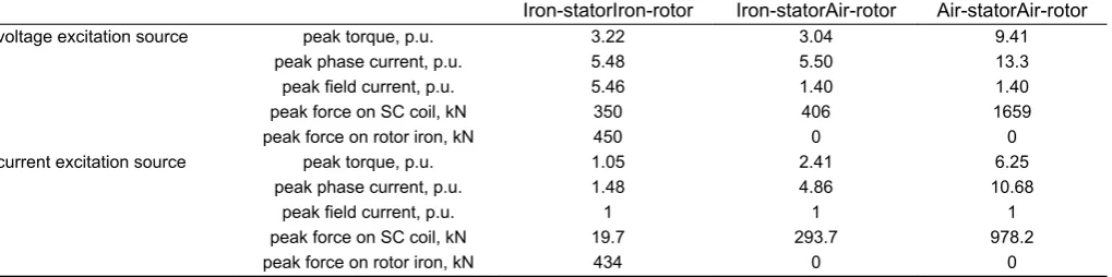
5 Summary
The short-circuit performances of SC generators with different topologies and different excitation sources are summarised in Fig. 11 and Table 2. When a generator is excited by a voltage excitation source, the air-cored stator and rotor topology has the highest peak fault torque, phase current, and force on SC coil, while the iron-cored stator and rotor topology has the highest peak field current. Overall, the iron-cored stator and air-cored rotor topology has the best short-circuit performance, in terms of fault Fig. 6 Forces on rotor components
(a) Forces on SC coil, iron-cored stator and rotor topology, (b) Forces on rotor iron, iron-cored stator and rotor topology, (c) Forces on SC coil, iron-cored stator and air-cored rotor topology, (d) Forces on SC coil, air-cored stator and rotor topology
Fig. 7 Variations of stator currents with time
(a) Phase currents, (b)Dq-axis currents
[image:5.595.53.290.42.667.2] [image:5.595.317.548.48.357.2]torque, phase, and field current, and force on SC coil. When a current excitation source is adopted, all of the performances are improved. The improvement for different topologies is different, and it is the most obvious for iron-cored stator and rotor topology. By comparing the short-circuit performance of different topologies with current excitation sources, the iron-cored stator and rotor topology is the best.
6 Conclusion
Although the short-circuit faults are usually rare and short-lasting in a generator system, the generator has to be designed carefully to withstand the associated transient peak fault torque, force, and currents etc. The performances of SC generators, with different topologies and different types of excitation sources, are analysed and compared here. The investigated topologies include iron-cored stator and rotor, iron-cored stator and air-cored rotor, and air-cored stator and rotor. The excitation sources include voltage and current sources. When a generator is excited by a voltage excitation source, the air-cored stator and rotor topology has the highest peak fault torque, phase current and force on SC coil, while the iron-cored stator and rotor topology has the highest peak field current. Overall, the iron-cored stator and air-cored rotor topology has the best short-circuit performance. When a current excitation source is adopted, all of the performances are improved. The improvement
for different topologies is different, and it is the most obvious for iron-cored stator and rotor topology.
Fig. 8 Variation of torque with time
Fig. 9 Variations of field current and flux linkage with time
(a) Current and, (b) Flux linkage
Fig. 10 Forces on rotor components
(a) Forces on SC coil, iron-cored stator and rotor topology, (b) Forces on rotor iron, iron-cored stator and rotor topology, (c) Forces on SC coil, iron-cored stator air-cored rotor topology, (d) Forces on SC coil, air-cored stator and rotor topology
[image:6.595.318.541.38.615.2] [image:6.595.54.276.173.491.2]7 References
[1] Umans, S.D.: ‘Transient performance of a high-temperature-superconducting generator’. Int. Conf. Electric Machines and Drives, Miami, USA, May 2009, pp. 451–457
[2] Liu, Y.Z., Qu, R.H., Zhu, Z., et al.: ‘Analysis on the performances of a rotor screen for a 12 MW superconducting direct-drive wind generator’, IEEE Trans. Appl. Supercond., 2014, 24, (5), pp. 1–5
[3] Sivasubramaniam, K., Huang, X., Laskaris, E.T., et al.: ‘Performance of an HTS generator field coil under system fault conditions’, IEEE Trans. Appl. Supercond., 2006, 16, (4), pp. 1971–1975
[4] Chen, H., Tsukamoto, O.: ‘Stability characteristics of fully superconducting and damperless generator with excitation control in fault condition’, IEEE Trans. Appl. Supercond., 1995, 5, (2), pp. 449–452
[5] Hatta, H., Nitta, T., Muroya, S., et al.: ‘Experimental study on sudden-short-circuit characteristic of synchronous generator with SCFCL’, IEEE Trans. Appl. Supercond., 2001, 11, (1), pp. 2343–2346
[6] Shafaie, R., Kalantar, M.: ‘Transient performance of a large scale wind turbine HTS synchronous generator under short circuit conditions’. Conf. Thermal Power Plants, Tehran, Iran, June 2014, pp. 99–102
[7] Jung, S.J., Kim, G.H., Sung, H.J., et al.: ‘Stator winding fault influence on the field coil of a 10 MW superconducting synchronous generator’, IEEE Trans. Appl. Supercond., 2013, 23, (3), p. 5200104
[image:7.595.193.408.47.183.2][8] Guan, Y., Zhu, Z.Q., Azar, Z., et al.: ‘Comparison of 10 MW superconducting generators with different topologies for offshore direct-drive wind turbines’, submitted to IEEE Trans. Appl. Supercond., 2017, 27, (7), pp. 1–11
Fig. 11 Short-circuit performances of SC generators with different topologies and different excitation sources, I-s I-r, I-s A-r, and A-s A-r represent iron-cored stator and rotor, iron-cored stator and air-cored rotor, and air-cored stator and rotor topologies, respectively
Table 2 Short-circuit performances of SC generators
Iron-statorIron-rotor Iron-statorAir-rotor Air-statorAir-rotor
voltage excitation source peak torque, p.u. 3.22 3.04 9.41
peak phase current, p.u. 5.48 5.50 13.3
peak field current, p.u. 5.46 1.40 1.40
peak force on SC coil, kN 350 406 1659
peak force on rotor iron, kN 450 0 0
current excitation source peak torque, p.u. 1.05 2.41 6.25
peak phase current, p.u. 1.48 4.86 10.68
peak field current, p.u. 1 1 1
peak force on SC coil, kN 19.7 293.7 978.2
peak force on rotor iron, kN 434 0 0
[image:7.595.45.555.228.355.2]