Int. J. Electrochem. Sci., 8 (2013) 11723 - 11733
International Journal of
ELECTROCHEMICAL
SCIENCE
www.electrochemsci.org
Effect of UV Radiation on Electrochemical Behavior of Polyurea
Polyaspartic Ester Coating in 3.5% NaCl by EIS
X.P Liu1,*, T.L Zheng 1, J.P. Xiong2,3
1
Material Science & Engineering School, Beihang University, Beijing 100191, China;
2
Key Laboratory of Carbon Fiber and Functional Polymer of Education Ministry, Beijing University of Chemical Technology, Beijing 100029, China;
3
The Beijing Key Laboratories of Materials Electrochemical Process and Technology, Beijing University of Chemical Technology, Beijing 100029, China
*
E-mail: [email protected]
Received: 26 June 2013 / Accepted: 10 August 2013 / Published: 10 September 2013
The effect of UV on corrosion electrochemical behavior of polyurea polyaspartic ester (PPE) coating in 3.5% NaCl solution was studied by electrochemical impedance spectroscopy (EIS). A series of impedance spectra of PPE coating during immersion was measured, and its protective properties were compared according to the spectra. The experimental results showed that UV radiation could accelerate the destroy process of the coating in 3.5% NaCl solution.
Keywords: polyurea polyaspartic ester coating, EIS, UV radiation
1. INTRODUCTION
More recently, EIS provides a rapid and convenient technique to evaluate the performance of organic coated metals. EIS has been proven to be a powerful tool in obtaining system specific parameters (coating capacitance, resistance coating. electrical double layer capacitance and charge transfer resistance of coatings) of organic coating and in evaluating the degradation of a coating on metals. This technique provides quantitative kinetic and mechanistic information which is very useful for developing improved coatings systems [16-19].
In this paper, EIS was used to monitor the degradations of the protective properties of the PPE coating during the immersion to a static 3.5% NaCl solution without and with UV radiation. Characteristics of electrochemical impedance spectroscopy during age of immersion were gained. Equivalent circuit (EC) models were proposed to interpret the electrochemical impedance data for the present coated systems. The protective properties of the coatings were evaluated and analyzed by electrochemical specific parameters of coating and breakpoint frequency. The result was offered the information of the corrosion resistance of the PPE coating in electrochemical parameters and effect of UV radiation on the coating protection.
2. EXPERIMENTAL
2.1 Experimental materilas
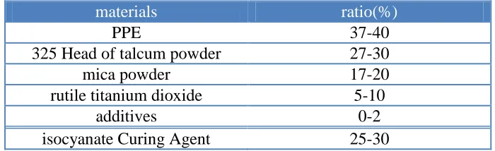
[image:2.596.123.473.490.597.2]Polyurea polyaspartic ester(PPE) was synthesized by double alkyl malay acid ester and bis-(p-aminocyclohexy)methane(PACM) via a Michael addition reaction.
Table 1. The chemical compostion of PPE coating
materials ratio(%)
PPE 37-40
325 Head of talcum powder 27-30
mica powder 17-20
rutile titanium dioxide 5-10
additives 0-2
isocyanate Curing Agent 25-30
Q235 ordinary carbon steel with nominal composition(wt%) of 0.30 C, 0.019 P, 0.029 S, 0.01 Si, 0.42 Mn, and balance Fe.
2.2 Preparation of samples
matching order. Coated for only one flat and the interval were 24 hours, thickness of the coating was controlled in about 150 μm. The rear and edge of the panels were protected by applying a thick epoxy film to avoid corrosion. The effective area of the coating was 13cm2.
2.3 Immersion and UV radiation of sample
The samples were immersed in 3.5% NaCl solution at room temperature, and the another sample was endured the combination action of immersion and UV radiation. During test, the UV light with the 325nm of wavelength and 1000W of power was kept 20cm to the samples immersed in 3.5% NaCl solution at room temperature. The sample was taken out regularly during immersion period and measured by EIS.
2.4 EIS Measurement
The electrochemical impedance measurement system of EG&G M388 was used in the experiments. EIS measurement system was composed of a PAR 273 potentiostat and a PAR 5210 lock-in amplifier. The EIS measurements were carried out over a frequency range of 100 kHz to 10 mHz using a 10 mV amplitude sinusoidal voltage. The coated samples were immersed in 3.5% NaCl which served acting as corrosion medium. A three-electrode cell arrangement was used in the experiments. The coated metal panel was the working electrode and a platinum plate served as the counter electrode. The reference electrode was a saturated calomel electrode (SCE). The tested area of working electrode was 13 cm2. All the measurements were performed at the open-circuit potential (OCP). The test cells were maintained at 25˚C and the NaCl solution was refreshed regularly during the whole test period. The impedance spectra were collected and analyzed for evaluating the protection properties of the coatings.
3. EXPERIMENTAL RESULTS
3.1 EIS of the coating in 3.5% NaCl solution with immersion time
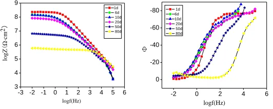
The impedance modulus values (/Z/) at the lowest measured frequency, 0.01Hz, may be taken as indicators of the state of the protective coating subjected to a medium that is aggressive to the metal[20]. Fig.1 gave the Bode plot of EIS spectra from the coating as the immersion time increased. It was evidence that, after 1 day exposure, a high impedance values at the low-frequency limit 0.01Hz (abbreviated as |Z|0.01 below ) displayed, which beyond 108Ω·cm2 ,and the phase angle was almost
close to 80°, just one time constant could be observed from the inspection of the impedance spectra. All these indicated that the coating had excellent protection performance, and could effectively protected metals from shielding corrosive medium.
Since being immersed for 20 days, the |Z|0.01 of the coating had descended to less than
the coating had been immersed into 3.5%Nacl solution, |Z|0.01 had been inferior to 106Ω·cm2, indicating
that the coating had lost the capability of protection [21]. However, all the studied coatings present an ionic resistance of more than 107Ω·cm2, a value above which coatings are considered to be in a good state and without deterioration [22] With the increasing of immersion time, the values of |Z|0.01
decreasing, as well the maximum phase angle shifted to higher frequencies, manifesting that the protective properties of the coating gradually decreased. The reason might be that the electrolyte penetrated the coating and created a path to the underlying surface [23-25].
Impedance data at high frequencies usually represented the responses of coating, thus exhibited the coatings characteristics and performance in the solution. The curve of the Bode spectra at the high frequency region overlapped each other as time increasing. That might be due to the saturation of electrolyte permeability, and the capacitance of the coating was no longer increasing substantially.
Two time constants in the impedance diagram eventually occurred after the longer exposure time of 50 days. At this stage of the coating degradation process, electrolyte solution penetrated to the coating/metal-substrate interface, while causing corrosion reactions to the base, and it also wakened the combine between coating and metal-substrate which resulted in blister or swelling[26].
-3 -2 -1 0 1 2 3 4 5 6 3
4 5 6 7 8 9
lo
g
Z
(
Ω
·cm
2)
logf(Hz)
1d 6d 10d 20d 50d 80d
-2 0 2 4 6 0
-20 -40 -60 -80
Φ
logf(Hz)
1d 6d 10d 20d 50d 80d
Figure 1. Bode spectra of polyurea polyaspartic ester coating at different times of exposure in 3.5% NaCl solution
[image:4.596.118.384.339.446.2]
0 1x10⁷
2x1073x1074x1075x107
0.0 2.0x10⁶ 4.0x10⁶ 6.0x10⁶ 8.0x10⁶ 1.0x10⁷
Zim
(Ω
cm
2
)Zre
(Ωcm2
)1d 6d 10d 20d 50d 80d
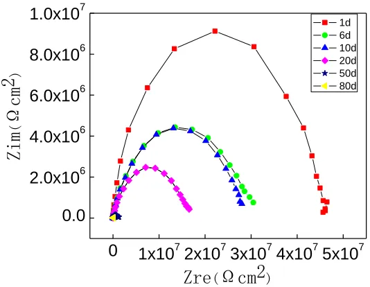
Figure 2. Nyquist spectra of polyurea polyaspartic ester coating at different times of exposure in 3.5% NaCl solution
0.0 5.0x10⁵ 1.0x10⁶ 1.5x10⁶ 2.0x10⁶
0 1x10⁵ 2x10⁵ 3x10⁵ 4x10⁵ 5x10⁵ Zi m ( cm 2)
Zre(cm2)
1d 6d 10d 20d 50d 80d
0.0 5.0x10⁴
1.0x10⁵ 1.5x10⁵ 2.0x10⁵ 2.5x10⁵ 0.0 2.0x10⁴ 4.0x10⁴ 6.0x10⁴ 8.0x10⁴ Zim ( Ω cm 2)
Zre(Ωcm2)
1d 6d 10d 20d 50d 80d
Figure 3. Partial enlarged drawing of Niquist spectra of Fig.2
[image:5.596.167.434.86.293.2] [image:5.596.109.389.370.472.2]
Figure 4. Equivalent circuits for the coating in 3.5% NaCl solution at different stages
3.2 EIS of the coating in 3.5% NaCl solution with immersion time under UV radiation
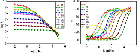
Fig.5 presented the Bode spectra at different times of exposure to 3.5% NaCl solution with ultraviolet radiation. From Fig.5, it could be shown that |Z|0.01 of the coating displayed high values
after 12 hours and 24hours exposure, the phase angle was almost reached 80°, and it had just one time constant. The result showed that the coating at this time was good shielding layer with large impedances and the matrix was protected well [29].
With the testing going on, the value of the impedance modulus descend gradually. Until 260 hours, an improvement of the impedance value appeared. It was an unusual phenomenon that may be interpreted by the “self-repaired” of the coating[30].
-2 0 2 4 6
3 4 5 6 7 8 9 10 lo g Z logf(Hz) 12 24 48 72 120 260 510 640 780 960
-2 0 2 4 6
0 -20 -40 -60 -80 -100 Φ logf(Hz) 12 24 48 72 120 260 510 640 780 960
Figure 5. Bode spectra of polyurea polyaspartic ester coating at different times of exposure in 3.5 NaCl solution with ultraviolet radiation
It was learned from Fig.6 that a semi-circle was generally observed after 12 hours exposure. It could be explained that with the increasing of immersion, electrolyte penetrated to organic coatings, and an ionic path was created in the coating. Then there was a reduction in the coating resistance and increase in the coating capacitance. EEC of the coating was generally represented as Fig.4(a), which included the solution resistance Rs, in series with a parallel combination of the coating capacitance CC
and the coating resistance RC.
For 72 hours, the Nyquist spectrum showed a large circular arc appeared in high frequency part, and a diagonal line in the low frequency. The circular arc in the high frequency displayed the property of the coating, thus the diagonal line in the low frequency was on behalf of the corrosion of the substrate. The result indicated that the corrosive medium had transfer through the coating to the metal interface, and the low frequency was controlled by diffusion process[31]. This behavior could be represented by the EEC in Fig.4(c).
After 510 hours exposure, the circular arc in the low frequency indicating corrosion of the substrate was also seen on Nyquist plot. Then with the subsequent testing, more electrolytes were accessible to the bare metal and accelerated further corrosion.
0 1x10⁸
2x10⁸ 3x10⁸ 0.0 3.0x10⁷ 6.0x10⁷ 9.0x10⁷ Zim (Ω·cm 2 )
Zre(Ω·cm2) 0.0 5.0x10
[image:7.596.114.384.84.187.2]
0.0 8.0x10⁵ 1.6x10⁶ 2.4x10⁶
0.0
2.0x10⁵
4.0x10⁵
6.0x10⁵
Zim
(Ω
·
c
m2
)
Zre(Ω·cm2)
Figure 6. Niquist spectra of polyurea polyaspartic ester coating at different times of exposure in 3.5 NaCl solution with ultraviolet radiation (a) exposure for 12 hours; (b) exposure for 72 hours; (c)exposure for 510hours
The corresponding EEC was showed as Fig.4(d), Warburg (W) impedance was brought to describe the direct passes for diffusion .At this stage, rust point and macro-holes could be observed by eyes, indicating the late immersion was coming. In the late immersion, because of the appearance of the macro-holes, a new diffusion layer appeared at the coating/matrix interface, while the concentration gradient in the organic coating disappeared.
4. DISCUSSION
The coating resistance Rc, which reflected the anti-penetrating ability of the coating to electrolyte solution, was an important parameter to evaluate the protective performance of the coating. And the coating capacitance Cc reflected the anti-permeability of the coating, which was closely related to the diffusion behavior of electrolyte solution in the coating[20]. When the electrolyte solution penetrated into the coating, Cc would change because of the altering of the dielectric constant of coating.
In addition, the coating porosity [32,33], as a significant parameter, was attained to evaluate or forecast the aging regular of the coating. It was defined as the ratio of the initial theory volume resistance to actual volume resistance.
p pt R R P (1)
A d
Rpt (2)
In equation, d was behalf of the coating thickness, A was the coating area, stand for conductivity of electrolyte, which is 2.34×10⁻³Ω-1·
[image:8.596.202.341.80.178.2]
Taking one with another, coating resistance RC gradually decreased and coating capacitance Cc
gradually increased as the increasing of exposure time, which was attributed to the initial water uptake into the coating[23-25]. For all aging test, the enhancement of the Cc revealed in the initial period of immersion and then declined slowly to a stable value, indicating that the water uptake gradually reached a saturation state. In comparison with UV, the curve of coating capacitance presented a special fluctuation, which ascend firstly and descend later during the early stage of corrosion, this fluctuation related to the “self-repairing” of the coating [29].
From the beginning the coating resistances decreased quickly and the capacitance increased quickly for each of the exposure conditions, that because of the electrolyte solution permeating into the coating. However, a few days later the difference among the diverse condition was seen clearly. During the whole testing period, compared with immersion with UV radiation, the coating resistance remained higher value. While the coating capacitances remained lower value of one order of magnitude in the immersion without UV radiation.
As immersion continued, the porosity values of the coatings became more negative, indicating that the protective nature of the coating was altered because of the diffusion of corrosive species through the coating [33].
0 480 960 1440 1920 -10
-8 -6 -4
logP
t(h) 3.5% NaCl 3.5% NaCl with UV
0 240 480 720 960 1200 1440 -9.5
-9.0 -8.5 -8.0 -7.5
3.5% NaCl 3.5% NaCl with UV
logc
t(h)
0 480 960 1440 1920 2
4 6 8 10
3.5% NaCl 3.5% NaCl with UV
logR
[image:9.596.101.390.368.622.2]t(h)
Then as the coating swelled, more transmission medium had penetrated gradually into coating through the micro-porous of coating and had gradually been induced pathway, the coating porosity gradually increased in the later stage of corrosion, which was different from the behavior of coating capacitance. It could be clearly observed from Fig. 7(a) that the coating in different aging condition had distinct impact on the porosity. In comparison with the immersion test in 3.5% NaCl solution without UV radiation, the porosity of the coating in immersion with UV radiation revealed a greater growth, which indicated the UV radiation could accelerate the destroy of the coating in 3.5% NaCl solution.
It was clearly that in the initial exposure time 24 hours, all of the Rc values of exposure to diverse aging condition almost reached 108 Ω. After that time, the values of Rc for the exposure to 3.5% NaCl solution with UV radiation declined down to only 1.864×10⁴ Ω at 72 hours exposing that the coating has been eroded completely. However, the coating for the immersion in 3.5% NaCl solution without radiation maintained a high impedance value of 5.167×10⁶Ω even1200 hours later, furthermore it had lost protective properties until 1920h. All these indicated the occurrence of corrosion of metallic substrate for the immersion with UV radiation was more easily than that for the immersion without UV radiation, and the protective performance of the coating for the immersion was decreased down under UV radiation[35].
It was easier to draw a conclusion, the protective performance of the coating for diverse aging condition in chronological order: immersion in 3.5% NaCl solution without UV radiation>immersion in 3.5% NaCl solution with UV radiation.
5. CONCLUSIONS
For diverse aging conditions, the protective performance of the coating displayed best for exposure to immersion in 3.5% NaCl solution with UV radiation, and UV radiation accelerated the destroy rate of the coating being immersed in 3.5% NaCl solution.
References
1. D.M. Xie, J.M. Hu, S.P. Tong, J.M. Wang, J.Q. Zhang, Acta Metall. Sin., 40(2004)103. 2. C.G. Oliveira, M.G.S. Ferreira, Corros. Sci., 45(2003)139.
3. G.P. Bierwagen, L. He, J. Li, Prog. Org. Coat., 39(2000) 67. 4. A. Amirudin, D. Thierry, Prog. Org. Coat., 26(1995)1.
5. H. Marchebois, M. Keddamb, C. Savalla, Electrochim. Acta, 49(2004)1719.
6. P. Carbonini, T. Monetta, L. Nicodemo, P. Mastronardi, B. Scatteia, F. Bellucci, Prog. Org. Coat., 29(1996)13.
7. L. Fedrizzi, F.J. Rodriguez, S. Rossi, Electrochim. Acta, (2001)3715.
8. W.B. Huang, Polyurea Elastomer Technology, Chemical Industry Press, Beijing(2005). 9. D.A. Wicks, P.E. Yeake, Prog. Org. Coat., 30(1997)165.
10.X.D. Qian, L. Song, B.B. Wang, Y. Hu, R.K.K. Yuen., Mater. Chem. Phys., 139(2013)443. 11.G.Y. Liu, W.B. Huang, Polyurethane Industry, 20(2005)16.
13.S.C. Xue, F.C. Xi, J.Z. Feng, X.Q. Chen, Q.C. Li, G.W. Wang, Modern Paint & Finishing, 12(2009)1.
14.P. Lv, G.P. Chen, W.B. Huang, China synthetic rubber industry, 4(2007)263.
15.L.C. Yeh, T.C. Huang, Y.P. Huang, H.Y. Huang, H.H. Chen, T.I. Yang, J.M. Yeh, Electrochim. Acta, 94(2013)300.
16.F. Mansfeld, J. Appl. Electrochem., 25(1995)187.
17.J. Leblanc, N. Gardner, A. Shukla, Compos. Part B-Eng., 44(2012)565. 18.P.L. Bonora, F. Deflorian, L. Fedrizzi, Electrochim. Acta, 41(1996)1073.
19.K.F. Khaled, N.S. Abdel-shafi, N.A. Al-Mobarak, Int. J. Electrochem. Sci., 7(2012)1027.
20.I. Díaz, B. Chico, D.de la Fuente, J. Simancas, J.M. Vega, M. Morcillo, Prog. Org. Coat., 69(2010)278.
21.J.R. Vilche, E.C. Bucharsky, Corros. Sci., 44(2002)1287. 22.C.C. Lee, F. Mansfeld, Corros. Sci., 41(1999)439.
23.S. Feliu, J.C. Galván, M. Morcillo, Prog. Org. Coat., 17(1989)143. 24.J.C. Galván, S. Feliu, M. Morcillo, Prog. Org. Coat., 17(1989)135. 25.S. Feliu, J.C. Galván, M. Morcillo, Corros. Sci., 30(1990)989.
26.H. Marchebois, C. Savall, J. Bernard, S. Touzain, Electrochem. Acta, 49(2004)2945. 27.J.M. McIntyre, H.Q. Pham, Prog. Org. Coat., 27(1996)201.
28.F. Mansfeld, C.H. Tsai, Corrosion, 47(1991)958.
29.Y.F. Zhu, J.P. Xiong, Y.M. Tang, Y. Zuo, Prog.Org. Coat., 69(2010)7. 30.A.S. Hamdy, A.M. Beccaria, Corros. Prev. Control, 48(2001)143. 31.A.S. Hamdy, Pro. Org. Coat., 55 (2006)218.
32.R.D. Armstrong, A.T.A. Jenkins, B.W. Johnson, Corros. Sci., 37(1995)1521. 33.R.D. Armstrong, J.D. Wright, Electrochim. Acta, 38(1993)799.
34.A.S. Hamdy, A.M. Beccaria, T. Temtchenko, Surf. Coat. Technol., 155(2002)176. 35.M. Hattori, A. Nishikata, T. Tsuru, Corrosion Sci., 52(2010)2080.