STUDY ON SINGLE STRUT FORMATION USING ADDITIVE LAYER
MANUFACTURING
CHEE YING CHEN
A thesis submitted
in fulfillment of the requirements for the degree of Bachelor of Mechanical Engineering (with Honours)
Faculty of Mechanical Engineering
UNIVERSITI TEKNIKAL MALAYSIA MELAKA
ii
DECLARATION
I declare that this project report entitled “Study On Single Strut Formation Using Additive Layer
Manufacturing” is the result of my own work except as cited in the references. The thesis has not been accepted for any degree and is not concurrently submitted in candidature of any other
degree.
Signature : ...
Name : CHEE YING CHEN
iii APPROVAL
I hereby declare that I have read this project report and in my opinion this report is sufficient in
terms of scope and quality for the award of the Bachelor of Mechanical Engineering (with Honours).
Signature : ...
Name of Supervisor : DR RAFIDAH BINTI HASAN
iv
DEDICATION
v
ACKNOWLEDGEMENT
First and foremost, I would like to take this opportunity to express my deep appreciation to my supervisor Dr. Rafidah binti Hasan, from the Faculty of Mechanical Engineering Universiti Teknikal Malaysia Melaka (UTeM) for guiding me very well throughout this project. Under her supervision, I had gained her guidance and inspiration that enable me to complete this final year
project successfully.
Moreover, I would like to express my greatest gratitude to Prof. Dr. Ghazali Bin Omar as my panel seminar and also second report examiner. Next, I would like to express my deepest gratitude to Associate Professor Dr Mohd Ahadlin bin Mohd Daud as my second panel seminar. He had lent the Dino-Lite Pro for me as well in order to complete the microscopic examination in this project.
Furthermore, I would like to thank to Universiti Teknikal Malaysia Melaka (UTeM) especially the Faculty of Mechanical Engineering (FKM) for giving a fully support by allowing me to use their equipments and facilities during conducting my project.
vi ABSTRACT
The lattice-structure materials are suitable for lightweight structural applications as they have the properties of flexible and high stiffness. In a lattice-structure material, its basic unit is single strut which is a member that connects two nodes. Hence, understanding the single strut properties is important in lattice-structure material study. This study is conducted to analyse layer by layer formation of fabricated single strut using a 3D printer with several parameters. The chosen diameters of single struts are 1.2mm, 1.4mm and 1.6mm while the build angles are set as 0o, 20o, 35.26o, 45o, 60o, 80o and 90o from a vertical line. All single struts are needed to be designed with suitable supports before proceed to fabrication stage. After three sets of 21 specimens are fabricated using CubePro 3D printer successfully, all single struts are analysed on their diameter using Dino-Lite Pro. The difference between measured diameter and designed
diameter for each single strut is recorded. Next, the selected single struts with 35.26o build angle
are analysed on their surface roughness using Dino-Lite Pro and 3D non-contact profilometer. A graph of surface roughness versus strut diameter is constructed for both equipment used. Thus, the results show that all single struts have the accuracy of more than 86% when comparing the readings of measured diameter and designed diameters. The single strut with 1.2mm diameter
for 35.26o build angles has the lowest Ra (Roughness Average) value. The comparison between
vii
ABSTRAK
viii
TABLE OF CONTENTS
DECLARATION ii
APPROVAL iii
DEDICATION iv
ACKNOWLEDGEMENT v
ABSTRACT vi
ABSTRAK vii
TABLE OF CONTENTS viii
LIST OF FIGURES x
LIST OF FIGURES FOR APPENDICES xii
LIST OF TABLES xiii
LIST OF ABBREVIATIONS xiv
LIST OF SYMBOLS xv
CHAPTER
1. INTRODUCTION 1
1.1 Background 1
1.2 Problem Statement 3
1.3 Objective 4
1.4 Scope of Project 4
1.5 Summary of Chapter 1 4
2. LITERATURE REVIEW 5
2.1 Introduction 5
2.2 Lattice-structure and Strut 5
2.3 Methods in Producing Lattice-structures 6
2.4 Additive Layer Manufacturing 8
2.5 Polymer 3D Printer 10
2.6 Summary of Chapter 2 11
3. METHODOLOGY 12
3.1 Introduction 12
3.2 Workflow Chart 12
ix
3.4 Fabrication Stage 16
3.5 Analysis Stage 20
3.6 Summary of Chapter 3 24
4. RESULTS AND DISCUSSION 25
4.1 Introduction 25
4.2 Design Stage 25
4.3 Fabrication Stage 29
4.4 Analysis Stage 31
4.5 Summary of Chapter 4 49
5. CONCLUSION AND RECOMMENDATION 50
5.1 Conclusion 50
5.2 Recommendation 51
REFERENCES 52
x
LIST OF FIGURES
FIGURE TITLE PAGE
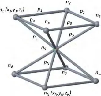
1.1 A strut-based lattice configuration with nodes n = 9 and struts p = 16 2
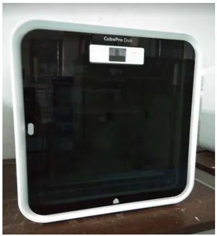
1.2 CubePro machine at Rapid Prototyping Laboratory 3
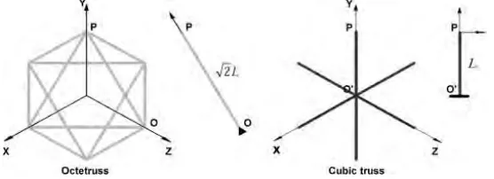
2.2 Octetruss and cubic truss 6
2.3.1 Octet-truss lattice structure 7
2.3.2 Sheet metal forming process 8
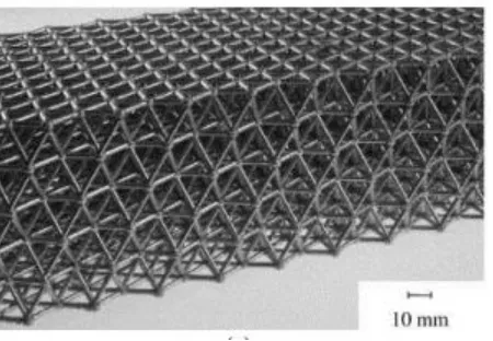
2.4 Fabricated struts with different diameters 9
2.5 CubePro 3D printer 11
3.2 Flow chart of the methodology 13
3.3.1 The part drawing of single struts with 35.26o using CATIA 15
3.3.2 The dimension drawing of single struts with 35.26o using CATIA 15
3.4.1 Build settings of CubePro software 16
3.4.2 Descriptions on the build settings 17
3.4.3 Single struts with slices in CubePro software 18
3.4.4 Printing process of struts using CubePro 3D printer 19
3.5.1 Detach the bottom support 20
3.5.2 Cut off the side bottom 21
xi
3.5.4 Single strut is labelled using (a) masking tape and (b) a marker pen 21
3.5.5 Three sets of printed single struts 22
3.5.6 A single strut is observed using Dino-Lite Pro 23
3.5.7 3D non-contact profilometer 24
4.2.1 Top view for printed single struts using CubePro 3D printer 26
4.2.2 Schematic diagram of overhang strut angles 26
4.2.3 Support angle setting 27
4.2.4 Specimens from feasibility tests 28
4.2.5 Several printed single struts on the printing bed 28
4.4.1 (a) Surface with no trimming and (b) trimmed surface of single strut 31
4.4.2 Magnification scale used in Dino-Lite software 31
4.4.3 Graph of strut diameter versus build angle 41
4.4.4 Surface roughness analysis for 1.2mm strut diameter using Dino-Lite
Pro 43
4.4.5 Surface roughness analysis for 1.4mm strut diameter using Dino-Lite
Pro 43
4.4.6 Surface roughness analysis for 1.6mm strut diameter using Dino-Lite
Pro 44
4.4.7 Surface roughness analysis for 1.2mm strut diameter using 3D
non-contact profilometer 45
4.4.8 Surface roughness analysis for 1.4mm strut diameter using 3D
non-contact profilometer 45
4.4.9 Surface roughness analysis for 1.6mm strut diameter using 3D
non-contact profilometer 46
4.4.10 Dino-Lite Pro analysis and 3D non-contact profilometer analysis 47
xii
LIST OF FIGURES FOR APPENDICES
FIGURE TITLE PAGE
A1 The dimension drawing of single struts with 0o using CATIA 54
A2 The dimension drawing of single struts with 20o using CATIA 55
A3 The dimension drawing of single struts with 35.26o using CATIA 56
A4 The dimension drawing of single struts with 45o using CATIA 57
A5 The dimension drawing of single struts with 60o using CATIA 58
A6 The dimension drawing of single struts with 80o using CATIA 59
A7 The dimension drawing of single struts with 90o using CATIA 60
A8 Set A of printed single struts 61
A9 Set B of printed single struts 61
A10 Set C of printed single struts 62
A11 Set D of printed single struts 62
A12 The readings of measured diameter for each single strut in Set 1 63
A13 The readings of measured diameter for each single strut in Set 2 63
A14 The readings of measured diameter for each single strut in Set 3 63
A15 The readings of peak values and valley values for the selected single
xiii
LIST OF TABLES
TABLE TITLE PAGE
3.3 Parameters of single struts 14
3.4.1 Process parameters selected for single struts 18
4.3 A set of successfully printed specimens 29
4.4.1 The readings of the measured diameter for each single strut 32
4.4.2 The percentage difference of each single strut 40
4.4.3 The selected struts for surface roughness analysis 42
xiv
LIST OF ABBEREVATIONS
ABS Acrylonitrile Butadiene Styrene
AM Additive Manufacturing
Avg D Average Diameter
BCC Body Centered Cubic
CAD Computer-Aided Design
CATIA Computer Aided Three-dimensional Interactive Application
CO2 Carbon Dioxide
EBM Electron Beam Melting
FDM Fused Deposition Modelling
PLA PolyLactic Acid
Ra Roughness Average
SEM Scanning Electron Microscope
SLM Selective Laser Melting
xv
LIST OF SYMBOL
n = Nodes
p = Struts
𝑚𝑏 = Mass of block
𝜌𝑠 = Density of the steel
L = Length of cell
𝑁1, 𝑁2, 𝑁3 = Number of cells along the width, length and height directions
𝑑
= Strut diameterx = Reading of measured diameter
N = Number of readings in a single strut
𝜎 = Standard deviation
𝑥̅ = Mean (average data)
𝑥𝑒 = Experimental value (measured diameter)
𝑥𝑎 = Actual value (designed diameter)
% = Percentage difference
𝑙 = Evaluation length
1 CHAPTER 1
INTRODUCTION
1.1 Background
Lattice-structure materials utilize the design principals of efficient, lightweight
macroscale structures, to mesoscale material architectures. By having the properties of high stiffness and strength-to-weight scaling, the lattice-structure materials are suitable for
lightweight structural applications. The basic unit of lattice-structure material is single strut. The assembly methods of the strut-based lattice structures are flexible because of the availability of the joint type. Hence, the complex geometries designs would prefer to apply the strut-based
lattice structures due to its flexible configurations (Doyoyo and Hu, 2006).
For designing strut-based lattice structures, a lot of feasible options can be proposed
within a defined volume as a lattice structure has variation number of nodes and struts. An example of lattice structure with its nodes (n) and struts (p) is shown in Figure 1.1. A node is a point where two or more struts join, while a strut is a connection or member that links two nodes
2
Figure 1.1: A strut-based lattice configuration with nodes n = 9 and struts p = 16. (Source: Syam et al., 2017)
There are many methods in fabricating lattice-structure material, such as casting, sheet metal forming, wire bonding process, selective laser melting (SLM) and electron beam melting (EBM) (Rashed et al., 2016). Casting is one of the conventional methods to produce lattice
structures by using injection molding and the mold is made by ceramic (Rashed et al., 2016). Sheet metal forming produces lattice structures by press forming operation from a roll of sheet
metal (Rashed et al., 2016). SLM and EBM are both methods that using additive manufacturing (AM) techniques where the part is produced layer by layer. For SLM process, its raw material used is metal powder and the part is formed by depositing a thin powder layer and scanning by
the laser(Gebhardt, 2003).
Additive layer manufacturing is an innovative method to fabricate lattice-structure
materials. 3D printing is also an additive manufacturing (AM) which the printed part is formed layer by layer. By using AM technology, the design of lattice structure is needed to be drawn using a CAD software before proceed to printing machine. AM technology is an advanced
3 1.2 Problem Statement
Understanding the single strut properties is important in lattice-structure material study. This is because, single strut is the basic unit of lattice-structure material. Different arrangement
of struts can produce different architecture of lattice-structure material. Moreover, by producing lattice-structure material using additive layer manufacturing, many controlling parameters affect the properties of material. In this study, fabricated single struts using additive manufacturing are
studied, in terms of its layer by layer formation. This is because there is no study done on investigating single strut using CubePro machine. Hence, the formation of single strut using
[image:18.612.201.424.352.594.2]material of polymer acrylonitrile butadiene styrene (ABS) and CubePro machine (Figure 1.2) will be examined at different diameter sizes and build angles.
4 1.3 Objective
The objective of this study is to analyse layer by layer formation of fabricated single strut using fused deposition modelling (FDM) machine with several parameters.
1.4 Scope of Project
The scopes of this project are:
1. To design single strut using CATIA (an acronym of computer aided
three-dimensional interactive application) at different size and angles.
2. To fabricate single struts using CubePro 3D printer and material of polymer
acrylonitrile butadiene styrene (ABS).
3. To evaluate the formation of single strut and relate it with process parameters
using microscopic examination, which is optical microscope and profilometer.
1.5 Summary of Chapter 1
In conclusion, the fabricated single struts using additive manufacturing are studied in order to quantify the single strut as a basic unit of lattice structure. By conducting this study, the
5 CHAPTER 2
LITERATURE REVIEW
2.1 Introduction
The background of this study is needed to be studied in order to have better
understanding before proceed for further progress. In this chapter, the relevant topics with this study are explained based on the journal articles and academic book. Moreover, the researches
that related to this study are discovered from the journal articles and described in this chapter as well.
2.2 Lattice-structure and Strut
Lattice-structure is formed by a number of struts and nodes. Node is a joint where struts
meet together while strut is the basic unit of lattice structure and also as a connection between nodes. For designing strut-based lattice structure, it can be designed in various types of
configuration due to the variation of node positions in a fixed volume. Lattice-structure has high stiffness-to-weight ratio, which means its materials used can be saved. Hence, the strut-based lattice structures are being applied in complex geometries designs as the problem of forming
can be eliminated (Doyoyo and Hu, 2006).
6
variation of the number of nodes and struts can lead to obtain a large number of options results,
the node positions and strut diameters can be variable in a specific volume as well (Syam et al., 2017). Strut-based lattice structure can be in various shape such as cubic truss and octetruss as
[image:21.612.175.453.190.291.2]shown in Figure 2.2.
Figure 2.2: Octetruss and cubic truss.
(Source: Doyoyo and Hu, 2006)
2.3 Methods in Producing Lattice-structures
Traditionally, lattice-structures are manufactured through casting, sheet metal forming, or wire bonding processes. These conventional manufacturing processes are time-consuming
and also limited the complexity of lattice-structure designs. These methods are only used to manufacture lattice-structure materials with simple configuration on a macroscale (Tang et al., 2017).
For casting process, a pattern of wax or polymer lattice-structure is coated with ceramic casting slurry. This ceramic is a mold and the wax or polymer is then removed through the
process of melting. The liquid metal with high fluidity can be used to fill in the empty mold in order to form lattice-structure material. By using this method, a wide range of shapes of lattice
7
shape. Figure 2.3.1 shows octet-truss lattice structure produced from casting process. With this
[image:22.612.204.429.198.354.2]casting process, the manufactured lattice-structure material had severe porosity and this method is expensive and time-consuming (Rashed et al., 2016).
Figure 2.3.1: Octet-truss lattice structure.
(Source: Rashed et al., 2016)
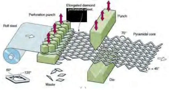
For sheet metal forming method, a roll of sheet metal is went through perforation punch to form the shaped holes such as hexagonal or diamond. The elongated perforated sheet is treated with annealing process to soften the struts before proceed to punching process. The perforated
sheet is then bent by the combinations of punch and die. This punching process allows the perforated sheet to be corrugated. Hence, a simple lattice-structure material can be manufactured
8
Figure 2.3.2: Sheet metal forming process.
(Source: Rashed et al., 2016)
However, the introduction of additive manufacturing (AM) technologies had reduced
the limitations in producing lattice-structure materials. AM technologies manufacture a part layer by layer and enables the design of lattice-structure materials in complex configuration. A
complex lattice-structure can be produced in ease through AM technologies and also in variation of geometrical scales such as microscale, mesoscale or macroscale (Reinhart et al., 2012).
2.4 Additive Layer Manufacturing
Generally, the first process of AM technology is to design and build a 3D modeling using
a CAD (Computer-Aided Design) software. This drawing is later converted into a “STL” (Standard Tessellation Language) file format which originates from 3D Systems. A computer program can read the STL file to create slices from the model for data preparation. This data is
9
3D printing is one of the additive layer manufacturing technologies. There are different
types of 3D printing and can be classified by depending on the raw materials such as solid-based, liquid based or powder based (Gebhardt, 2003). A lattice-structure material or single strut can
be fabricated by using 3D printing which is done within one process only where the part is generated layer-by-layer (Kessler et al., 2016).
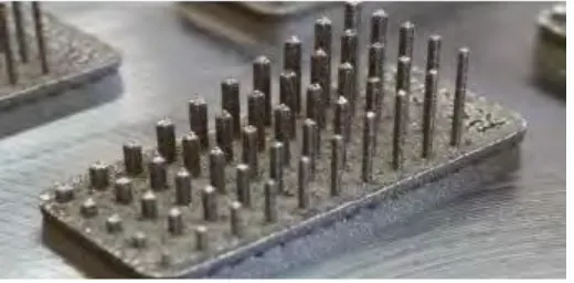
There was a study on producing strut shape of lattice-structure using SLM (Selective
Laser Melting) method. It was a powder-based AM technology and its raw material used was metal powder. During SLM process, a thin powder layer was deposited, and CO2 (carbon
dioxide) laser was irradiated to the powder surface successively until final part was produced based on CAD data. It focused on few types of cross sectional shape of struts and its reached quality. The examined shapes were circular, elliptical, square, triangular and rhombus. By
producing these struts, the limitations of SLM process were evaluated. For example, the limitation for circular cross section was the nominal diameter which smaller than 0.15mm
[image:24.612.185.445.502.630.2]cannot be fabricated (Kessler et al., 2016). Figure 2.4 shows the fabricated struts with different diameters.
Figure 2.4: Fabricated struts with different diameters.