AWAKE, The Advanced Proton Driven Plasma Wake
fi
eld Acceleration
Experiment at CERN
E. Gschwendtner
b, E. Adli
v, L. Amorim
g, R. Apsimon
c,j, R. Assmann
e, A.-M. Bachmann
l,
F. Batsch
l, J. Bauche
b, V.K. Berglyd Olsen
v, M. Bernardini
b, R. Bingham
o, B. Biskup
b,d,
T. Bohl
b, C. Bracco
b, P.N. Burrows
i,w, G. Burt
c, B. Buttenschön
m, A. Butterworth
b,
A. Caldwell
l, M. Cascella
s, E. Chevallay
b, S. Cipiccia
x, H. Damerau
b, L. Deacon
s, P. Dirksen
r,
S. Doebert
b, U. Dorda
e, J. Farmer
f, V. Fedosseev
b, E. Feldbaumer
b, R. Fiorito
c,t, R. Fonseca
g,
F. Friebel
b, A.A. Gorn
a,n, O. Grulke
m, J. Hansen
b, C. Hessler
b, W. Ho
fl
e
b, J. Holloway
i,w,
M. Hüther
l,q, D. Jaroszynski
x, L. Jensen
b, S. Jolly
s, A. Joulaei
l, M. Kasim
i,w, F. Keeble
s,
Y. Li
c,u, S. Liu
r, N. Lopes
h,g, K.V. Lotov
a,n, S. Mandry
s, R. Martorelli
f, M. Martyanov
l,
S. Mazzoni
b, O. Mete
c,u, V.A. Minakov
a,n, J. Mitchell
c,j, J. Moody
l, P. Muggli
l,
Z. Najmudin
h,i, P. Norreys
w,o, E. Öz
l, A. Pardons
b, K. Pepitone
b, A. Petrenko
b,
G. Plyushchev
b,p, A. Pukhov
f, K. Rieger
l,q, H. Ruhl
k, F. Salveter
b, N. Savard
l,r,y, J. Schmidt
b,
A. Seryi
i,w, E. Shaposhnikova
b, Z.M. Sheng
x, P. Sherwood
s, L. Silva
g, L. Soby
b,
A.P. Sosedkin
a,n, R.I. Spitsyn
a,n, R. Trines
o, P.V. Tuev
a,n, M. Turner
b, V. Verzilov
r, J. Vieira
g,
H. Vincke
b, Y. Wei
c,t, C.P. Welsch
c,t, M. Wing
s,e, G. Xia
c,u, H. Zhang
c,ta
Budker Institute of Nuclear Physics SB RAS, Novosibirsk 630090, Russia b
CERN, Geneva, Switzerland c
Cockcroft Institute, Warrington WA4 4AD, UK d
Czech Technical University, Zikova 1903/4, 166 36 Praha 6, Czech Republic eDESY, Notkestrasse 85, 22607 Hamburg, Germany
fHeinrich-Heine-University of Düsseldorf, Moorenstrasse 5, Düsseldorf 40225, Germany
gGoLP/Instituto de Plasmas e Fusão Nuclear, Instituto Superior Técnico, Universidade de Lisboa, Lisbon, Portugal h
John Adams Institute for Accelerator Science, Blackett Laboratory, Imperial College London, London SW7 2BW, UK i
John Adams Institute for Accelerator Science, Oxford, UK j
Lancaster University, Lancaster LA1 4YR, UK k
Ludwig-Maximilians-Universität, Munich 80539, Germany
lMax Planck Institute for Physics, Föhringer Ring 6, München 80805, Germany mMax Planck Institute for Plasma Physics, Wendelsteinstr. 1, Greifswald 17491, Germany n
Novosibirsk State University, Novosibirsk 630090, Russia o
STFC Rutherford Appleton Laboratory, Didcot OX11 0QX, UK p
Swiss Plasma Center, EPFL, Lausanne 1015, Switzerland q
Technische Universität München (TUM), Arcisstrasse 21, D-80333 Munich, Germany r
TRIUMF, 4004 Wesbrook Mall, Vancouver V6T2A3, Canada sUCL, Gower Street, London WC1E 6BT, UK
tUniversity of Liverpool, Liverpool L69 7ZE, UK u
University of Manchester, Manchester M13 9PL, UK v
University of Oslo, Oslo 0316, Norway w
University of Oxford, Oxford OX1 2JD, UK x
University of Strathclyde, 16 Richmond Street, Glasgow G1 1XQ, UK y
University of Victoria, 3800 Finnerty Rd, Victoria, Canada
Contents lists available atScienceDirect
journal homepage:www.elsevier.com/locate/nima
Nuclear Instruments and Methods in
Physics Research A
http://dx.doi.org/10.1016/j.nima.2016.02.026
a r t i c l e i n f o
Article history:
Received 30 November 2015 Received in revised form 5 February 2016 Accepted 9 February 2016
Keywords: AWAKE
Proton driven plasma wakefield accelera-tion
Linear accelerators Plasma wakefield Electron acceleration
a b s t r a c t
The Advanced Proton Driven Plasma Wakefield Acceleration Experiment (AWAKE) aims at studying plasma wakefield generation and electron acceleration driven by proton bunches. It is a proof-of-principle R&D experiment at CERN and the world'sfirst proton driven plasma wakefield acceleration experiment. The AWAKE experiment will be installed in the former CNGS facility and uses the 400 GeV/c proton beam bunches from the SPS. Thefirst experiments will focus on the self-modulation instability of the long (rms12 cm) proton bunch in the plasma. These experiments are planned for the end of 2016. Later, in 2017/2018, low energy (15 MeV) electrons will be externally injected into the sample
wake-fields and be accelerated beyond 1 GeV. The main goals of the experiment will be summarized. A summary of the AWAKE design and construction status will be presented.
&2016 The Authors. Published by Elsevier B.V. This is an open access article under the CC BY license (http://creativecommons.org/licenses/by/4.0/).
1. Introduction
AWAKE is a proof-of-concept acceleration experiment with the aim to inform a design for high energy frontier particle accel-erators and is currently being built at CERN [1,2]. The AWAKE experiment is the world's first proton driven plasma wakefield acceleration experiment, which will use a high-energy proton bunch to drive a plasma wakefield for electron beam acceleration. A 400 GeV/c proton beam will be extracted from the CERN Super Proton Synchrotron, SPS, and utilized as a drive beam for
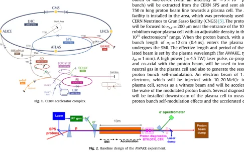
wake-fields in a 10 m long plasma cell to accelerate electrons with amplitudes up to the GV/m level.Fig. 1shows the AWAKE facility in the CERN accelerator complex. In order to drive the plasma wakefields efficiently, the length of the drive bunch has to be on the order of the plasma wavelength λpe, which corresponds to E1 mm for the plasma density used in AWAKE (1014–1015 elec-trons/cm3). The proton beam for AWAKE has a bunch length of
σz¼12 cm, therefore the experiment relies on the self-modulation instability (SMI) [3], which modulates the proton driver at the plasma wavelength in thefirst few meters of plasma. The SMI is a transverse instability that arises from the interplay between
transverse components of the plasma wakefields and the
wake-fields being driven by regions of different bunch densities. The modulation period sffiλpe and the modulated bunch resonantly drives the plasma wakefields. The occurrence of the SMI can be detected by characterizing the longitudinal structure of the proton beam when exiting the plasma cell.
In the AWAKE master schedule, the experiment to obtain evi-dence for the SMI corresponds to Phase 1, and is expected to start by the end of 2016. In Phase 2, AWAKE aims at thefirst demon-stration of proton-driven plasma wakefield acceleration of an electron witness beam; this programme is planned to start by the end of 2017. At a later phase it is foreseen to have two plasma cells in order to separate the modulation of the proton bunch from the acceleration stage. Simulations[4]show that this would optimize the acceleration of external electrons and reach even higher gradients.
1.1. Baseline design
In the baseline design of AWAKE at CERN, an LHC-type proton bunch of 400 GeV/c (with an intensity of 31011
protons/ bunch) will be extracted from the CERN SPS and sent along the 750 m long proton beam line towards a plasma cell. The AWAKE facility is installed in the area, which was previously used for the CERN Neutrinos to Gran Sasso facility (CNGS)[5]. The proton beam will be focused toσx;y¼200μm near the entrance of the 10 m long rubidium vapor plasma cell with an adjustable density in the 1014– 1015electrons/cm3range. When the proton bunch, with an r.m.s. bunch length of σz¼12 cm (0.4 ns), enters the plasma cell, it undergoes the SMI. The effective length and period of the modu-lated beam is set by the plasma wavelength (for AWAKE, typically
[image:2.595.38.525.447.754.2]λpe¼1 mm). A high power (E4.5 TW) laser pulse, co-propagating and co-axial with the proton beam, will be used to ionize the neutral gas in the plasma cell and also to generate the seed of the proton bunch self-modulation. An electron beam of 1:2109 electrons, which will be injected with 10–20 MeV/c into the plasma cell, serves as a witness beam and will be accelerated in the wake of the modulated proton bunch. Several diagnostic tools will be installed downstream of the plasma cell to measure the proton bunch self-modulation effects and the accelerated electron Fig. 1. CERN accelerator complex.
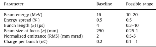
bunch properties.Fig. 2shows the baseline design of the AWAKE experiment. The baseline parameters of the proton beam, laser and plasma cell are summarized inTable 1; those of the electron beam inTable 2.
2. The AWAKE beams: proton, electron, laser
2.1. Proton beam line
For the main part of the beam line, the 750 m long CNGS transfer line can be reused without major changes. However, in the last 80 m a chicane has been integrated in order to create space for a mirror of the laser beam line, necessary to merge the ionising laser pulse with the proton beam about 22 m upstream the plasma cell. The proton beam is shifted horizontally by 20 mm at the position of the laser mirror in the present layout[6]. Two beam position monitors (BPMs) and a beam loss monitor (BLM) are placed around the merging mirror in order to interlock the SPS extraction in case the mirror is hit by the proton beam. The syn-chronization of the two co-propagating beams has to be stable to 100 ps and the transverse pointing accuracy of the proton beam at its focal point is required to be r100μm and r15μrad, so that the proton trajectory is coaxial with the laser over the full length of the plasma cell. Beam position monitors and screens (BTVs) in
combination with a streak camera close to the plasma cell allow the overlap and synchronization of the beams to be measured. Optics simulations predict a 1σ spot size of 210μm at the focal point in agreement with the experiment requirements (see Table 1).
2.2. Electron source
The electron source for AWAKE consists of a 2.5 cell RF-gun and a one meter long booster structure both at 3 GHz (seeFig. 3). The electron beam is produced via photo-emission by illuminating a cathode with a frequency quadrupled laser pulse which is derived from the main drive laser for the plasma. The wavelength used in the photo injector will be 262 nm. The baseline will use copper cathodes with a quantum efficiency of Qe104. However, thanks to the integration of a load lock system, which allows transferring cathodes under ultra high vacuum, different cathodes could be used: e.g. Cs2Te with a quantum efficiency ofQe102. A 30 cell travelling wave structure was designed to boost the energy with a constant gradient of 15 MV/m up to a total electron energy of 20 MeV. The RF-gun and the booster are powered by a single klystron delivering about 30 MW. The operation mode will be single bunch with a maximum repetition rate of 10 Hz. In addition the electron source is equipped with BPMs with a reso-lution of 50 μm to control the beam position, a fast current transformer with a resolution of 10 pC, a Faraday Cup, and two emittance measurement stations. Details of the electron source are described in[7]. The PHIN Photo-Injector built for CTF3[8]will be used as the RF-gun for AWAKE. The RF power source will also be recuperated from the CTF3.
2.3. Electron beam line
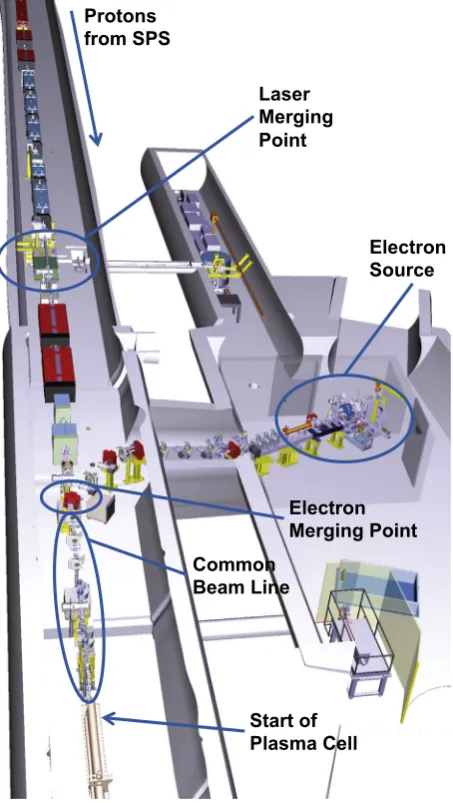
The electron source is installed in an adjacent room 1.16 m below the level of the proton beam line. The electron transfer line consists of an achromatic dog-leg to raise the electron beam up to the level of the proton line and a part which bends the electron beam horizontally onto the proton beam axis. Details of the beam line design are described in[9].Fig. 4shows the layout of electron beam line, together with the proton and laser beam lines in the AWAKE facility. Directly after the accelerating structure of the electron source a quadrupole triplet matches the electron beam into the transfer line (seeFig. 3). Another quadrupole triplet just before the plasma is used to focus the beam into the plasma. Five additional quadrupoles are used to control the dispersion and the beta function. While the dispersion in the horizontal plane is almost zero along the part of the beam line downstream of the merging dipole (common line with the protons), the dispersion in the vertical plane is not closed due to the vertical kick given by the tilted dipole, which merges the electron beam onto the proton beam axis. However, the final focusing system matches the beta functions and dispersion to the required 1σspot size ofr250μm at the focal point in both planes. Longitudinally the focal point is set at an iris (orifice) with a free aperture of 10 mm about 0.5 m upstream of the plasma cell. The present optics provides the possibility to shift the focal point up to 0.8 m into the plasma cell without significant changes of the beam spot size. Ten kickers (correctors) along the electron beam line compensate systematic alignment andfield errors and a shot-to-shot stability of7100μm is predicted for a currentfluctuation of 0.01% in the power con-verters. In the common beam line upstream the plasma cell the proton, electron and laser beam are travelling coaxially. Studies on the proton induced wakefields on the beam pipe walls and their effect on the electrons show that the influence of the proton beam wakefields on the electrons is negligible [10]. However, direct beam–beam effects show that the electron beam emittance blows Table 1
AWAKE proton, laser beam and plasma parameters.
Parameter Baseline
Proton beam
Beam momentum 400 GeV/c
Protons/bunch 31011
Bunch extraction frequency 0.03 Hz (ultimate: 0.14 Hz)
Bunch length (σ) 0.4 ns
Bunch size at plasma entranceðσx;yÞ 200μm Normalized emittance (RMS) 3.5 mm mrad Relative energy spread (Δp/p) 0.035% Beta functionðβn
x;yÞ 4.9 m
DispersionðDnx;yÞ 0
Laser beam to plasma
Laser type Fibre titanium: sapphire
Pulse wavelength (L0) 780 nm
Pulse length 100–120 fs
Laser power 4.5 TW
Focused laser sizeðσx;yÞ 1 mm
Energy stability (RMS) 71.5%
Repetition rate 10 Hz
Plasma source
Plasma type Laser ionized rubidium vapor
Plasma density 71014cm3
Length 10 m
Plasma radius Z1 mm
Skin depth 0.2 mm
[image:3.595.42.292.389.464.2]WavebreakingfieldE0¼mcωcp=e 2.54 GV/m
Table 2
AWAKE electron beam parameters.
Parameter Baseline Possible range
Beam energy (MeV) 16 10–20
Energy spread (% ) 0.5 0.5
Bunch length (σ) (ps) 4 0.3–10
Beam size at focus (σ) (mm) 250 0.25-1 Normalized emittance (RMS) (mm mrad) 2 0.5-5
up[11]. In addition to the beam–beam effect, the most efficient electron injection into the plasma wakefields must be optimized. The trapping of the electrons in the plasma was analysed with respect to the transverse vertical position y and angle y0 at
injection [12]. Combining the results of these studies show a possible optimized injection scheme; the electron beam is offset in the common beam line and this offset is kept also at the injection point (seeFig. 5). Adding a kicker magnet close to the plasma cell and focusing the beam into the iris allows to inject the electrons into the plasma wakefield with an offset of up to 3.25 mm and an angle between 0 and 8 mrad[9].
2.4. Laser beam line
The laser system is housed in a dust-free, temperature-stabilized area (class 4) and includes the laser, pulse compressor and laser beam transport optics[13]. The laser beam line to the plasma cell starts at the output of the optical compressor in the laser lab and is transported via a newly drilled laser core. The laser beam line is enclosed in a vacuum system, which is attached to the compressor's vacuum chamber and to the proton beam line vacuum system at the merging point, which is at a vacuum level of 107mbar. The deflection of the laser beam will be performed with dielectric mirrors held by motorized mirror mounts, installed in the vacuum system. The size of the laser beam and the focusing spatial phase will be controlled by a dedicated telescope just before the pulse compressor. The focal distance is to be adjustable in the range between 35 and 45 m.
A diagnostic beam line will be installed in the proton tunnel for measuring the beam properties of a low energy replica of the ionizing beam in exactly the distance which corresponds to the plasma cell location.
The laser beam for the electron gun will be taken from the second output of the base version of the laser system, further amplified to E30 mJ, compressed to 300 fs using an in-air com-pressor, frequency converted to 262 nm via a Third Harmonics Generation and stretched to the desired pulse length of 10 ps.
2.5. Low-level RF and synchronization
[image:4.595.131.456.57.245.2]The proton, electron and the high power laser pulse have to arrive simultaneously in the rubidium plasma cell. The proton bunch is extracted from the SPS about every 30 s and must be synchronized with the AWAKE laser and the electron beam pulsing at a repetition rate of 10 Hz. The latter is directly generated using a photocathode triggered by part of the laser light, but the exact time of arrival in the plasma cell still depends on the phase of the RF in the accelerating structure. Each beam requires RF signals at characteristic frequencies: 6 GHz, 88.2 MHz and 10 Hz for the Fig. 3.Electron source and accelerating structure layout.
Protons
from SPS
Laser
Merging
Point
Electron
Source
Electron
Merging Point
Common
Beam Line
Start of
Plasma Cell
[image:4.595.46.273.271.673.2]synchronization of the laser pulse, 400.8 MHz and 8.7 kHz for the SPS, as well as 3 GHz to drive the accelerating structure of the electron beam [14]. A low-level RF system and distribution has been designed to generate all signals derived from a common reference. Additionally precision triggers, synchronous with the arrival of the beams, will be distributed to beam instrumentation equipment to measure the synchronization. Phase drifts of the opticalfibers transporting the RF signals for the synchronization of the SPS with AWAKE will be actively compensated by newly developed hardware, which is essential to achieve a link stability of the order of 1 ps.
3. Plasma source
AWAKE will use a rubidium vapor source[15]ionized by a short laser pulse (seeTable 1). Rubidium plasma consists of heavy ions, that mitigate plasma ions motion effects. The plasma cell is 10 m long and has a diameter of 4 cm. The density uniformity is achieved by imposing a uniform temperature (within 0.2%) along the source. For that purpose a heat exchanger with sufficient heat carryingfluid
flow is used. Synthetic oil is circulated inside a thermal insulation around the tube containing the rubidium vapor. The oil temperature can be stabilized to70.05°C. A threshold ionization process for the
first Rb electron is used to turn the uniform neutral density into a uniform plasma density. The ionization potential is very low,
ΦRb¼4.177 eV, as is the intensity threshold for over the barrier ionization (OBI),IIoniz1:71012W=cm2.
At the two ends of the 10 m long plasma cell fast valves were foreseen originally, with the fast valves open only to let the proton, laser and electron beam pass. However, gas dynamic simulations of the Rb vaporflow showed that the fast valves were not fast enough (1–3 m) to ensure a short enough density ramp: for
efficient electron trapping one needs the density ramp shorter than E10 cm. To meet this requirement the vapor cell ends will now have a continuousflow through orifices at each end[13]. The Rb sources should be placed as close as possible to the orifices to minimize the density ramp length. Thus there is continuousflow of Rb from the sources to the plasma cell and afterwards from the plasma cell to the expansion volumes through the orifices (10 mm diameter). The walls of the expansion volumes should be cold enough (39°C, the melting temperature of Rb) to condense all Rb atoms. The density gradient in the plasma cell will be controlled by the temperature difference of the Rb sources at each end of the plasma cell. In order to control a density gradient of 0.5–% with at least 50% precision the relative reservoir temperatures must be controlled with a precision of 0.1°C or better.
4. Electron injection
In order to optimize the electron acceleration in the plasma various schemes for electron injection have been investigated. The history of the evolution on the optimized electron injection for AWAKE is described in [16]. In the first experimental phase the electron bunch will be at least one plasma period long in order to avoid exact phasing with the proton bunch modulation and thus cover several modulation cycles. Once the SMI is better under-stood and optimal parameters are found, it is planned to inject short electron bunches at the desired phase.
4.1. Oblique injection
[image:5.595.134.471.60.213.2]At the plasma entrance the plasma density increases smoothly from zero to the baseline density of 71014electrons/cm3. Elec-trons initially propagating along the proton beam axis are not Fig. 5.The 3σenvelope of the electron beam in the common beam line, in case the electron beam is coaxial with the proton beam (OnAxis) or with an offset to the proton beam axis (Offset). The position and free aperture of the main beam line elements are represented by blue squares. (For interpretation of the references to color in thisfigure caption, the reader is referred to the web version of this paper.)
rubidium vapor
plasma
laser pulse
proton bunch
electron bunch
r
z
flaser pulse
trapped electrons modulated proton bunch
e
α
idefocusing region
[image:5.595.141.467.267.373.2]trapped by the plasma wave in case the plasma density increases over a too long distance. The effect is similar to the plasma lens effect[17]and is explained in detail in[16]. For the parameters of the AWAKE experiment, a transition region of 10 cm length is sufficient to defocus the electrons.
To shorten the transition area, the plasma cell ends are designed with a continuousflow through orifices as described in Section 3. With this design the defocusing region is on the order of 15 cm. This distance is still sufficient to deliver a radial momentum of about 0.5 MeV/c to the electrons thus preventing their trapping by the plasma wave. But fortunately the defocusing region does not extend beyond the radial plasma boundary[16]. So the elec-trons that are outside the ionized area in the plasma transition region propagate freely and some of them can even receive a small focusing push of several mrad.
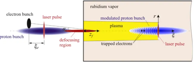
Applying an oblique electron injection as shown in Fig. 6 mitigates the loss of the electrons at the plasma density transition region: the electrons have a small radial offset with respect to the proton beam upstream the plasma cell and are injected with a small angleαiinto the plasma. In this way they approach the axis in the region of already constant plasma density and therefore can get trapped into the established plasma wave. The optimum values for the oblique injection scheme found in simulations are [16]: electron delay ξe¼11:5 cm, injection angle αi¼2:8 mrad, and focusing pointzf¼140 cm. These values are compatible with the range of settings for the electron beam line (seeSection 2.3) and therefore no changes in the facility design are required.
4.2. Density gradient along the plasma
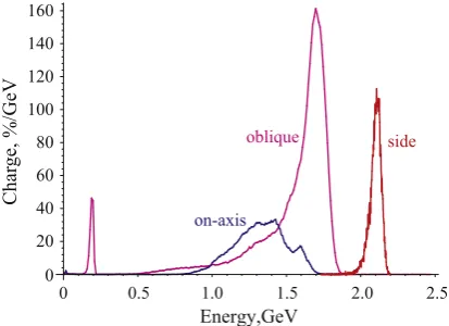
With the plasma cell design as described inSection 3a plasma density gradient of several percent along the 10 m long plasma cell can be created. If the gradient is positive the resulting change of the wakefield structure optimizes the electron acceleration. Details of these studies are described in[18].Fig. 7shows thefinal energy of the electrons after passing through the 10 m long plasma cell for oblique, on-axis and side-injection. (In side-injection, the electrons would be injected into the plasma cell only after the SMI has developed. This has turned out to be technically very challenging and was abandoned for thefirst phases of the experiment[6].) The results show that with oblique injection, realistic plasma bound-aries at both ends and the linear growth of the plasma density by 1% over 10 m, about 40% of the injected electrons are trapped and accelerated toE1.8 GeV after 10 m.
5. Diagnostics
5.1. Direct SMI measurements
The direct SMI diagnostic tools are based on transition radia-tion measurements[19].
The optical transition radiation (OTR) is prompt and its time structure reflects that of the bunch charge density hitting the radiator foil placed in the beam path. For AWAKE the plasma and modulation frequency range is 100–300 GHz. The time structure of the light and the proton bunch can be characterized using affi1 ps resolution streak camera. The ability of the streak camera to detect the ps modulation of the light signal was tested using beating laser beams; the results show that the period of the modulation can be measured for frequencies of up to 300 GHz[13].
Coherent transition radiation (CTR) diagnostics uses time-resolved and heterodyne frequency measurements to determine the frequency and possibly amplitude of the SMI. The CTR has a radially polarized electricfield and has a maximum emission at a certain angle that depends on the particular experimental condi-tions of the plasma density. This makes it difficult to couple into the fundamental mode of circular or rectangular wave-guides, therefore using quasi-optical propagation to handle the CTR beam at least in the vicinity of the interaction point is considered. The CTR can be detected when focused onto a pyro-detector or to couple part of a beam into a horn antenna and then detect it with the help of Schottky diodes.
5.2. Indirect SMI measurement
Protons in the defocusing phase of the wakefields exit the plasma close to the plasma center and appear as a narrow core on transverse profiles downstream the plasma. In [20]it is shown that the defocusing angle is on the order of 1 mrad for the 400 GeV/c protons. For the indirect SMI measurements two beam-imaging screens (BTVs) at a distance of E8 m will be inserted downstream the plasma cell in order to measure the transverse bunch shape and the beam size. Detailed studies of the screen material showed that a 1 mm thick Chromox-6 (Al2O3:CrO2) scintillator with a hole or an OTR material at the beam centre can measure the beam shape and produce enough light, with only minimal interference of the proton beam. A defocused beam edge resolution of 0.6 mm can be achieved[20].
5.3. Electron spectrometer
The electron spectrometer system[21] consists of a C-shaped dipole providing a 1.5 Tfield to separate the electrons from the proton beam and disperse them in energy onto a scintillating screen (baseline is gadolinium oxysulfide). The spectrometer sys-tem also includes a quadrupole doublet in a point-to-point ima-ging configuration, to focus the beam exiting the plasma onto the spectrometer screen and increase the energy resolution. An optical line will transport the screen light to a CCD camera. Radiation protection calculations showed that the CCD camera needs to be located at a position 17 m away from the screen in order to avoid radiation damage. Calculations show that by transporting the light to the camera using a series of mirrors and a suitable commercially available lens a peak signal to noise ratio of at least 120 is achieved at the expected electron acceleration capture efficiency.
6. The AWAKE underground facility and safety aspects
Modifying the CNGS underground high radiation area for AWAKE beam requires challenging modifications in a complex 0
20 40 60 80 100 120 140 160
Ve
G/
%
,e
gr
a
h
C
Energy,GeV
0 0.5 1.0 1.5 2.0 2.5
on-axis
[image:6.595.55.262.58.208.2]oblique side
experimental area. AWAKE services and infrastructure must be integrated within the existing radiation facility and at the same time be designed and installed to keep the radiation dose to per-sonnel as low as possible. Shielding was installed and CNGS ele-ments dismantled or exchanged in order to turn the high-radia-tion, no-access CNGS facility into a supervised radiation area with safe regular access. Fig. 4shows the integration of the AWAKE beam lines in the CNGS facility; the diagnostics is downstream of the plasma cell and not seen in thefigure.
Fire safety equipment and the access procedures must be modified following extensivefire risk assessments, in order to deal with the specific AWAKE access needs (a stop-and-go proof-of-principle experiment) and properties of the new equipment. Because of the high radiation, materials in CNGS were limited to concrete, iron, graphite, etc. leading to a very low fuel load of the area. The much lower radiation level in AWAKE means that racks, electronics and other equipment with a non-negligible fuel load are still installed in an underground area that is 1 km distance from the nearest exit. In order to guaranteefire safety, a new and more complexfire zone layout was created. Fire resistant walls and doors will ensure that at least two evacuation paths are available for every AWAKE area. Fire risk assessment were per-formed for the regions with the higher fuel loads (e.g. the oil-based Klystron for the electron source), fire intervention and evacuation exercises are organised and the fire safety and eva-cuation information will be part of a dedicated AWAKE safety course, obligatory for every person wanting to enter the area.
Radiation protection calculations have been performed using FLUKA Monte Carlo code[22,23]to study the radiation environ-ment in the AWAKE facility. The results show that access to the AWAKE experimental area has to be prohibited during the proton beam operation as the prompt dose equivalent rate exceeds 100 mSv/h. As a consequence, the experiment and equipment must be remotely controlled. To allow partial access to the laser room and the klystron area during the operation of the electron beam, an appropriate shielding wall around the electron gun has to be designed. During electron operation radiation levels in accessible areas will be continuously monitored. Moreover, a dedicated air management system of the area including an air-borne radioactivity monitor has to be installed to guarantee safe access conditions after proton beam operation.
7. Summary
AWAKE is a proof-of-principle accelerator R&D experiment currently being built at CERN. It is thefirst proton-driven
wake-field acceleration experiment worldwide, with the aim to provide a design for a particle physics frontier accelerator at the TeV scale. The installation of the AWAKE experiment is advancing well. Hardware and beam commissioning is planned for thefirst half of 2016. The physics of the self-modulation instability as a function of the plasma and proton beam properties will be studied starting by the end of 2016. The longitudinal accelerating wakefield will be probed with externally injected electrons starting by the end of 2017. At a later stage it is foreseen to have two plasma cells in
order to separate the modulation of the proton bunch from the acceleration stage and to reach even higher gradients.
Acknowledgments
This work was supported in parts by: EU FP7 EuCARD-2, Grant Agreement 312453 (WP13, ANAC2); and EPSRC and STFC, United Kingdom. The contribution of Novosibirsk team to this work is supported by The Russian Science Foundation, Grant no. 14-12-00043. The AWAKE collaboration acknowledges the support of CERN, Max Planck Society, DESY, Hamburg and the Alexander von Humboldt Stiftung.
References
[1] A. Caldwell et al., AWAKE Design Report, A Proton-Driven Plasma Wakefield Acceleration Experiment at CERN, Internal Note CERN-SPSC-2013-013, CERN, Geneva, Switzerland, 2013.
[2]R. Assmann, et al., AWAKE Collaboration, Plasma Physics and Control Fusion 56 (2014) 084013.
[3]N. Kumar, A. Pukhov, K. Lotov, Physical Review Letters 104 (2010) 255003. [4]A. Caldwell, K. Lotov, Physics of Plasma 18 (2011) 103101.
[5] E. Gschwendtner et al., Performance and Operational Experience of the CNGS Facility, in: Proceedings of the 1st International Particle Accelerator Con-ference, IPAC2010, Kyoto, Japan, THPEC046, 2010.
[6] C. Bracco et al., in: Proceedings of IPAC2014, Dresden, Germany, 2014. [7] K. Pepitone, S. Doebert et al., The electron accelerator for the AWAKE 436
experiment at CERN, EAAC2015, Elba, Italy, these proceedings, 2015. [8] G. Geschonke et al., CTF3 Design Report, Technical Report
CTF3-Note-2002-047, CERN, Geneva, 2002.
[9] J. Schmidt et al, Status of the Proton and Electron Transfer Lines for 441 the AWAKE Experiment at CERN, EAAC2015, Elba, Italy, these proceedings, 2015. [10] U. Dorda et al., Simulations of Electron–Proton Beam Interaction before Plasma
in the AWAKE Experiment, IPAC15, Richmond, USA, 2015.
[11] U. Dorda, et al., Propagation of electron and proton beams before the plasma (2015)https://indico.cern.ch/event/403300/.
[12] A. Petrenko et al., Latest electron trapping simulation results, 2015,https:// indico.cern.ch/event/403300/.
[13] A. Caldwell at al., AWAKE Status Report, CERN-SPSC-2015-032, SPSC-SR-169, 2015.
[14]M. Bernardini, et al., AWAKE, a Proof-of-Principle R&D Experiment at CERN, IPAC15, Richmond, USA (2015).
[15] E. Öz, F. Batsch, P. Muggli, An acccurate Rb density measurement 454 method for a plasma wakefield accelerator experiment using a novel Rb 455 reservoir, EAAC2015, Elba, Italy, these proceedings, 2015.
[16] A. Caldwell and AWAKE Collaboration, Path to AWAKE: Evolution of 457 the concept, EAAC2015, Elba, Italy, these proceedings, 2015.
[17] P. Chen, Particle Accelerators 20 (1987) 171.
[18] A. Petrenko, K. Lotov, A. Sosedkin, Numerical Studies of Electron Ac461 cel-eration Behind Self-Modulating Proton Beam in Plasma with a Density 462 Gradient, EAAC2015, Elba, Italy, these proceedings, 2015.
[19] P. Muggli, AWAKE, proton-driven plasma wakefield experiment at 464 CERN, IPAC15, Richmond, USA, 2015.
[20] M. Turner et al., Indirect Self-Modulation Instability Measurement Concept for the AWAKE Proton Beam, EAAC2015, Elba, Italy, these proceedings, 2015. [21] L.C. Deacon et al., Development of a spectrometer for proton driven plasma
wakefield accelerated electrons at AWAKE, IPAC15, Richmond, USA, 2015. [22] G. Battistoni, S. Muraro, P.R. Sala, F. Cerutti, A. Ferrari, S. Roesler, A. Fasso, J.
Ranft, in: M. Albrow, R. Raja eds., Proceedings of the Hadronic Shower Simulation Workshop 2006, Fermilab 6–8 September 2006, AIP Conference Proceedings, vol.896, 2007, pp. 31–49.