City, University of London Institutional Repository
Citation:
Kloukinas, C. and Ozkaya, M. (2014). Realizable, Connector-Driven Software
Architectures for Practising Engineers. Communications in Computer and Information
Science, 457, pp. 273-289. doi: 10.1007/978-3-662-44920-2_17
This is the accepted version of the paper.
This version of the publication may differ from the final published
version.
Permanent repository link:
http://openaccess.city.ac.uk/4288/
Link to published version:
http://dx.doi.org/10.1007/978-3-662-44920-2_17
Copyright and reuse: City Research Online aims to make research
outputs of City, University of London available to a wider audience.
Copyright and Moral Rights remain with the author(s) and/or copyright
holders. URLs from City Research Online may be freely distributed and
linked to.
City Research Online:
http://openaccess.city.ac.uk/
[email protected]
for Practising Engineers
Mert Ozkaya and Christos Kloukinas
City University London School of Informatics London EC1V 0HB, U.K.
{mert.ozkaya.1,c.kloukinas}@city.ac.uk
Abstract. Despite being a widely-used language for specifying software sys-tems, UML remains less than ideal for software architectures. Architecture de-scription languages (ADLs) were developed to provide more comprehensive sup-port. However, so far the application of ADLs in practice has been impeded by at least one of the following problems: (i) advanced formal notations requiring a steep learning curve, (ii) lack of support for user-defined, complex connectors, and (iii) potentially unrealizable architectural designs.
This paper proposes XCD, a new ADL that aims at supporting user-defined, com-plex connectors to help increase architectural modularity. It also aims to help in-crease the degree of reusability, as now components need not specify interaction protocols, as these can be specified independently by connectors (which increases protocol reusability too).
Connector support requires to ensure that architectural designs are always realiz-able, as it is currently extremely easy to obtain unrealizable ones. XCDeliminates potentially unrealizable constructs in connector specifications.
Finally, XCDemploys a notation and notions from Design-by-Contract (DbC)
for specifying software architecture behaviour. While DbC promotes a formal and precise way of specifying system behaviours, it is not as challenging for practising developers as process algebras that are usually employed by ADLs.
Keywords: Component Based Software Engineering; Software architecture; Mod-ular specifications; Connector realizability; Separation of functional and interac-tion behaviours; Design-by-Contract.
1
Introduction
and (iii) potential for producing unrealizable designs. Indeed, to the best of our knowl-edge, there is no ADL that is easy to learn, treats connectors as first-class elements and ensures that architecture specifications are realizable.
While condition (i) has been identified by practitioners as being a serious imped-iment to their adoption of current ADLs [19], condition (ii) is not an issue that they consider as crucial, as does a number of researchers since many ADLs do not support complex connectors. Nevertheless, we believe that it can substantially help in develop-ing concise designs, as it increases modularity and reusability by allowdevelop-ing designers to reuse not only components but interaction protocols as well, thus facilitating architec-tural exploration and avoiding reuse-by-copy. Condition (iii) is in fact something that has not been identified at all so far to the best of our knowledge but we believe that it is crucial to identify and resolve, if a connector-centric ADL is to succeed among practitioners. Below we briefly examine each of these issues.
Formal notations Many ADLs (e.g., Wright [1], LEDA [6], SOFA [24], CONNECT [15], etc.) adopt formal notations, e.g., process algebras [4], for specifying the be-haviours of architectural elements. They do so in order to enable the architectural anal-ysis of systems, which is extremely important in uncovering serious system design er-rors early on in the lifetime of a project. Indeed, if such an analysis is not possible, then there is no point in using a specialized language for software architectures – even sim-ple drawings suffice. However, ADLs employ notations that practitioners view (with reason) as having a steep learning curve [19]. Thus, practitioners end up avoiding them and use instead simpler languages, even if that means that they lose the ability to prop-erly describe and analyse their systems – better an informal description of a system that everybody understands than a formal description of a system that people struggle understanding.
(a) The nuclear power plant’s requirements (b) An unavoidable bad behaviour
Fig. 1: A nuclear power plant [2]
connectorPlant Connector=
roleP1= ur→na→P1.
roleP2= ur→na→P2.
roleNA = increment→NA⊓double→NA.
roleUR = increment→UR⊓double→UR.
glue=P1.ur→UR.increment→P1.na→NA.increment
→P2.ur→UR.double→P2.na→NA.double→glue
P2.ur→UR.double→P2.na→NA.double→P1.ur
→UR.increment→P1.na→NA.increment→glue.
Fig. 2: Wright’s(unrealizable)connector for Alur’s nuclear power plant
Potentially unrealizable designs The third problem of existing ADLs is that when they do support user-defined, complex connectors, they do so in a way that can lead to unre-alizable designs. All ADLs in this category follow the approach initiated by Wright [1] and require connectors to include a glue element. In Wright [1], a connector role spec-ifies the “obligations of [a] component participating in the interaction” and a glue specifies “how the activities of the [. . . ] roles are coordinated.” – a connector glue is supposed to be more than simple definition/use relationships. The fact that the glue can introduce inter-role interaction constraints is deeply problematic because these con-straints cannot always be implemented in a decentralized manner by the components that assume the connector roles, as these can only observe their local state [27, 28]. In fact, it has been shown that the general problem of deciding whether a glue is realizable is undecidable [2, 3, 27, 28], so there is no general algorithm that can be implemented to warn architects that the glue they are specifying is not realizable by the existing roles. The only easy solution to realize a protocol then is to introduce yet another component that will assume the role of the glue, thus transforming all protocols into centralized ones and potentially invalidating architectural analyses concerning scalability, perfor-mance, reliability, information flows, etc.
An example of such an unrealizable protocol is the simplified nuclear power plant [2], shown in Fig. 1a. The interaction therein involves two client roles (P1and P2)
[image:4.595.138.460.122.202.2]to avoid nuclear accidents, for which reason we wish to allow only the sequences shown in Fig. 1a. The interaction of the two clients with the NA and UR variables, can easily be specified in Wright as in Fig. 2. Note that this glue specification does two things. First it establishes bindings between clients and servers (e.g., P1.ur→UR.increment). Then it
constraints interactions by requiring that we only allow UR.increment→NA.increment or UR.double→NA.double. This specification is however unrealizable [2] because it is impossible to implement it in a decentralized manner in a way that avoids behaviours excluded by the glue, e.g., the one depicted in Fig. 1b. The only way to achieve the desired behaviour is to introduce another role, for a centralized controller G. Roles P1
and P2then need to inform G when they wish to interact with UR and NA and have G
perform the interactions with UR and NA in their place.
2
Our Approach
The ADL we are developing, called XCD, tries to overcome the problems identified in the previous section and offer:(i)first-class support for user-defined, complex con-nectors;(ii)realizable software architectures by construction; and(iii)a simple to un-derstand, yet formal, language for specifying behaviour, based on design-by-contract (DbC).
2.1 Support for Complex Connectors
XCDgrants connectors in software architectures first-class status, allowing designers to specify both simple interaction mechanisms and complex protocols. These can then be instantiated as many times as needed, allowing architects to simplify the specifications of their components and easily reuse the specification of complex protocols.
To illustrate how important this is for both architectural understandability and also analysis, we will use a simple example from electrical engineering. Let us considerk
concrete electrical resistors,r1,· · ·,rk, i.e., our system components. When using a
se-quential connector (→), the overall resistance is computed asR→(N,{Ri}Ni=1) =∑Ni=1Ri,
whereN,Riare variables (Ricorrespond to connector roles), to be assigned eventually some concrete valuesk,rj. If using a parallel connector (k) instead, it is computed as
Rk(N,{Ri}Ni=1) =1/∑Ni=11/Ri. So the interaction protocol (connector) used is the one
that gives us the formula we need to use to analyse it – if it does not do so, then we are probably using the wrong connector abstraction. The components (rj) are simply providing some numerical values to use in the formula, while the system configuration tells us which specific value (k,rj) we should assign to each variable (N,Ri) of the connector-derived formula. By simply enumerating the wires/connections between re-sistors/components, we miss the forest for the trees. This leads to architectural designs at a very low level that is not easy to communicate and develop – as [8] found the case to be with AADL.
→ r1,||
→(r2,r3),
r4
! !
(a) Simple connectors, i.e., wires (b) Complex connectors
Fig. 3: Connectors in circuits
also becomes difficult and architectural errors can go undetected until later develop-ment phases. Indeed, we are essentially forced to reverse-engineer the architect’s intent in order to analyse our system – after all, the architect did not select the specific wire connections by chance but because they form a specific complex connector. When com-plex connectors are employed instead as in Fig. 3b then the number of connectors to be considered is reduced substantially. This makes it much easier to understand the system and to analyse its overall resistance by taking advantage of the connector properties as:
R→(r
1,||(→(r2,r3),r4))=r1+R||(→(r2,r3),r4)=r1+
1
1
R→(r2,r3)+
1
r4
=r1+
1
1
r2+r3+
1
r4
The use of connectors allows us to separate interaction patterns/protocols from com-ponents and renders comcom-ponents independent from these – resistors do not need to know if they will be connected in series or in parallel. Both modularity and reuse (for both components and protocols) are increased. Unlike physical systems, where configuration patterns are enough to specify connectors as interaction in them is governed by known physical laws, software systems connectors also need to specify role interaction.
2.2 Realizable Software Architectures
Connectors in our ADL are not specified with glue-like elements. Instead, we consider connectors as a simple composition of roles, which represent the interaction behaviour of participating components, and built-in sub-connectors (i.e., links) that allow actions of one role to reach another. Coordination is now the responsibility of roles alone. If a particular property is desired then it must be shown that the roles satisfy it. But this is a problem that is decidable for finite state systems – model-checking. Thus an architect can easily specify a protocol and be sure that it has the required properties. Designers can also feel reassured that the architectural protocols are indeed realizable in principle, without the need to transform them into centralized ones, which might invalidate ar-chitectural analyses concerning scalability, performance, reliability, information flows, etc., as aforementioned.
the more experienced architect. The less experienced designers do not have to waste their time trying to achieve the impossible or take the easy (and dangerous) way out and turn a decentralized protocol into a centralized one. We essentially turn the glue from constraints to be imposed, to a property that needs to be verified, thus turning an undecidable problem that the less experienced designers have to deal with, into a de-cidable one for them (and pushing the responsibility to resolve the issue to the more experienced architect).
2.3 Design-by-Contract for Architecture Specifications
The Java Modelling Language (JML) [7] seems to be gaining popularity among devel-opers, as they use it for “test-driven development” and even for static analysis in some instances. XCDattempts to follow this trend so as to maximize adoption by practition-ers. Thus, it departs from the ADLs that adopt process algebras, and instead follows a Design by Contract (DbC) [21] approach like JML, specifying behavioural aspects of systems through simplepairs of method pre-/post-conditions, in a syntax reminiscent of JML. DbC allows for a formal specification of systems, as it is based on Hoare’s logic [13] and VDM’s [5] rely-guarantee specification approach. DbC has so far been mainly considered for programming languages (e.g., Java through JML), which is why contracts have been restricted to provided services (i.e., class methods).
There are very few ADLs that employ DbC. The work of Schreiner et al. [26] along with the TrustME ADL [25] are some of the very few examples applying DbC at the level of software architecture. Schreiner et al.’s work transforms connectors into com-ponents themselves, which we believe loses many of the connector benefits, as these are needed to essentially drive the component interactions. Doing so through wrapper-like components [26] makes it difficult to control component required ports, i.e., the ones initiating calls. This is because a wrapper-like explicit connector can delay a call request, while a proper connector can ensure that it never gets triggered at all. TrustME does not provide support for user-specified, complex connectors at all, as it essentially follows the approach of Darwin [18], enriching it with contracts.
Our approach attempts to apply DbC in a more comprehensive manner, covering component methods and events. As we view connectors as first-class elements, we use DbC to specify their behaviour as well. XCDfurther extends DbC by structuring com-ponent port action contracts into separate functional and interaction parts.
3
DbC-based Specifications with X
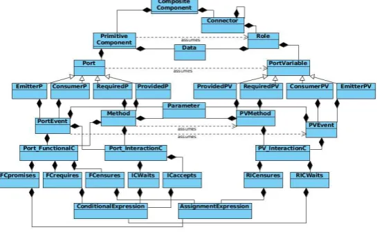
CDFig. 4 gives the meta-model of the XCD language. There are two main elements for specifying software architectures with XCD: components (primitive and composite ones), used to specify abstractions of computational units in a system, and connectors, that specify the complex interaction protocols of components.
Fig. 4: Meta-model of XCD
the data has been initialized – otherwise, it rejects the request and commences a chaotic behaviour.
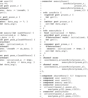
The XCDspecification of the shared-data access is given in Fig. 5. Two primitive component types are specified,userin lines 1–13 andmemoryin lines 15–31. Both the user and the memory comprise data-variables (line 2 and line 16 respectively) represent-ing their states and ports that are the points of interaction with their environment. There is also a connector typememory2userspecified (lines 1–32 at the right side), which represents the interaction between a memory and a user. Connector memory2user uses some other connectors (here built-in ones) to establish the communication links be-tween its role ports (lines 26–31). Its roles (userRoleat line 6 andmemoryRoleat line 14) constrain the behaviour of the components that assume them. Finally, we specify a composite component typesharedData(lines 34–44 at the right side), which includes component and connector instances and represents their configuration.
Primitive Component Types Componentuserhas a required portpuser_r(lines 3–7) through which it makes method calls to its environment (i.e., the memory) to retrieve the value of some data. Portpuser_r has a single methodget, whose functional contract
ensurespost-assignment clause (lines 4–5) assigns the method’s result to the compo-nent data – it has no pre-condition (i.e., arequires clause). Componentuseralso has an emitter portpuser_e (lines 8–12) to emit events. Portpuser_e declares a single eventset, whose functional contractpromisesclause assigns its parameter to 7 – the event has no pre-condition (i.e., arequiresclause) or post-assignment (i.e., anensures
1component user (){ 2 i n t data :=0;
3 r e q u i r e d p o r t p u s e r _ r {
4 @Functional{
5 e n s u r e s: data := \r e s u l t; } 6 i n t get ();
7 }
8 e m i t t e r p o r t p u s e r _ e {
9 @Functional{
10 p r o m i s e s: d a t a _ a r g := 7; } 11 set (i n t d a t a _ a r g );
12 } 13} 14
15component memory (i n t n u m O f U s e r s ) { 16 b o o l i n i t i a l i z e d _ m := f a l s e; 17 i n t s h _ d a t a := 0;
18 p r o v i d e d p o r t pmem_p [ n u m O f U s e r s ] { 19 @ I n t e r a c t i o n{
20 a c c e p t s: i n i t i a l i z e d _ m ; }
21 @Functional{
22 e n s u r e s: \r e s u l t := s h _ d a t a ; } 23 i n t get ();
24 }
25 consumer p o r t pmem_c [ n u m O f U s e r s ] {
26 @Functional{
27 e n s u r e s: i n t i a l i s e d _ m := t r u e; 28 s h _ d a t a := d a t a _ a r g ; } 29 set (i n t d a t a _ a r g );
30 } 31}
1c o n n e c t o r m e m o r y 2 u s e r (
2 u s e r R o l e { pvuser_r ,
3 p v u s e r _ e } ,
4 m e m o r y R o l e { pvmem_p ,
5 p v m e m _ c }) {
6 r o l e u s e r R o l e {
7 r e q u i r e d p o r t p v u s e r _ r { 8 i n t get ();
9 }
10 e m i t t e r p o r t p v u s e r _ e { 11 set (i n t d a t a _ a r g ); 12 }
13 }
14 r o l e m e m o r y R o l e {
15 b o o l i n i t i a l i z e d := f a l s e; 16 p r o v i d e d p o r t p v m e m _ p {
17 @ I n t e r a c t i o n{ w a i t s: i n i t i a l i z e d ; } 18 i n t get ();
19 }
20 consumer p o r t p v m e m _ c { 21 @ I n t e r a c t i o n{
22 e n s u r e s: i n i t i a l i z e d := t r u e; } 23 set (i n t d a t a _ a r g );
24 } 25 }
26 c h a n n e l a s y n c
27 u s e r 2 m e m o r y _ m ( u s e r R o l e { p v u s e r _ r } , 28 m e m o r y R o l e { p v m e m _ p }); 29 c h a n n e l a s y n c
30 u s e r 2 m e m o r y _ e ( u s e r R o l e { p v u s e r _ e } , 31 m e m o r y R o l e { p v m e m _ c }); 32};
33
34component s h a r e d D a t a () {// C o m p o s i t e 35 component user user1 ();
36 component user user2 (); 37 component memory mem (2); 38 c o n n e c t o r m e m o r y 2 u s e r 39 x1 ( user1 { puser_r , p u s e r _ e } , 40 mem { pmem_p [0] , p mem_c [0]}); 41 c o n n e c t o r m e m o r y 2 u s e r
[image:9.595.164.475.118.464.2]42 x2 ( user2 { puser_r , p u s e r _ e } , 43 mem { pmem_p [1] , p mem_c [1]}); 44}
Fig. 5: Shared-data access in the XCDADL
Componentmemoryhas an array of provided portspmem_p(lines 18–24). It uses each of these ports to provide methodgetto a differentusercomponent instance. Unlike the contracts of componentuser, the contract of these ports have an additional@Interaction
Complex Connector Types Connector type memory2user (lines 1–32 at the right of Fig. 5) specifies the protocol used in the system between the memory and the users. It serves to ensure that the memory will not behave chaotically. The connector has two roles,userRole(lines 6–13) andmemoryRole(lines 14–25). RoleuserRolehas a required port-variablepvuser_r(lines 7–8), reflecting portpuser_rof componentuser, and an emitter port-variable pvuser_e (lines 10–11), reflecting port puser_e. These port-variables do not impose any interaction constraints on the role.
RolememoryRolehas a provided port-variablepvmem_p(lines 16–19) reflecting port pmem_pof componentmemory. Unlike the port-variables ofuserRole, this port-variable introduces extra interaction constraints on the behaviour of its methods. It requires that calls to methodgetare considered only when the role’sinitializeddata is true, thus delaying them while this condition is not satisfied.
The role’s consumer port-variablepvmem_c (lines 20–24) reflects port pmem_c of componentmemory. It uses its interaction contract to note that the memory has been set, through itsensuresclause. The combination of the contracts of the two ports means that the memory cannot start behaving chaotically, as requests at non-accepting states are delayed until they are safe.
Composite Component Types ThesharedDatacomponent type (lines 34–44 at the right of Fig. 5) includes two instances of theuser component and a single instance of the memorycomponent. The component instances are passed as arguments to the two con-nector instances, in lines 38–43, to bind them together and constrain their interactions.
XCD Notation and Expressiveness As can be seen by Fig. 5, the notation used for DbC in the XCDADL follows a JML-like syntax, which should prove much easier for practitioners to understand and use effectively than formal languages such as process algebras. Indeed, we would expect one to be able to use XCDwith minimal training. At the same time, XCDintroduces connector constructs that are essentially (decentralized) algorithms (i.e., protocols) – configuration patterns of component variables, on which we have imposed additional interaction constraints. Apart fromπ calculus’ ability to send channels as messages, which XCDdoes not support, the XCDADL should allow architects to express the static architectures that one can express now with ADLs based on process algebras. However, XCDdoes not support dynamic architectures currently.
4
X
CDSemantics
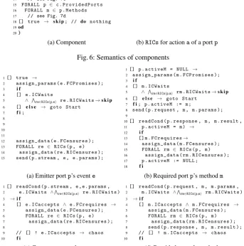
Fig. 6 shows the general behaviour of a (primitive) component described using Dijk-stra’s guarded command language [9]. Each instance is a concurrent process, that ini-tializes its data and then enters a loop, executing the actions of its ports (lines 6–12) or performing a skip action (line 14). The behaviour of port actions is shown in Fig. 7 for the four different port types.
1FORALL c ∈ Model . C o m p o n e n t s 2p r o c e s s c ... {
3// i n i t i a l i z a t i o n of data 4Start :
5do
6 FORALL p ∈ c . E m i t t e r P o r t s 7 FORALL e ∈ p . Ev ents 8 // see Fig. 7a
9 FORALL p ∈ c . R e q u i r e d P o r t s 10 FORALL m ∈ p . M e t h o d s 11 // see Fig. 7b
12 FORALL p ∈ c . C o n s u m e r P o r t s 13 FORALL e ∈ p . Eve nts 14 // see Fig. 7c
15 FORALL p ∈ c . P r o v i d e d P o r t s 16 FORALL m ∈ p . M e t h o d s 17 // see Fig. 7d
18[] true → s k i p; // do n o t h i n g 19od
20}
1 // all a s s o c i a t e d
2 // Role I n t e r a c t i o n C o n s t r a i n t s 3RICs ( port p , a ction a ) {
4 pvs = p . a s s o c i a t e d P o r t V a r i a b l e s ; 5 return S
pv∈pvs pv . a . RICs ; 6}
[image:11.595.127.471.231.578.2](a) Component (b)RICsfor actionaof a portp
Fig. 6: Semantics of components
1[] true →
2 a s s i g n _ p a r a m s ( e . F C P r o m i s e s ); 3 i f
4 [] e . I C W a i t s
5 ∧ Vre∈RICs(p,e) re . R I C W a i t s→s k i p
6 [] e l s e → goto Start
7 f i; 8 9 10 11
12 a s s i g n _ d a t a ( e . F C e n s u r e s ); 13 FORALL re ∈ RICs (p , e ) 14 a s s i g n _ d a t a ( re . R I C e n s u r e s ); 15 send ( p . stream , e , e . params );
1[] p . a c t i v e M = NULL →
2 a s s i g n _ p a r a m s ( m . F C P r o m i s e s ); 3 i f
4 [] m . I C W a i t s
5 ∧ Vrm∈RICs(p,m) rm . R I C W a i t s→s k i p 6 [] e l s e → goto Start
7 f i; p . a c t i v e M := m ;
8 send ( p . request , m , m . params ); 9
10[] r e a d C o n d ( p . response , m , m . result , 11 p . a c t i v e M = m ) →
12 i f
13 [] m . F C r e q u i r e s→
14 a s s i g n _ d a t a ( m . F C e n s u r e s ); 15 FORALL rm ∈ RICs (p , m ) 16 a s s i g n _ d a t a ( rm . R I C e n s u r e s ); 17 p . a c t i v e M := NULL ;
18 f i
(a) Emitter portp’s evente (b) Required portp’s methodm
1[] r e a d C o n d ( p . stream , e , e . params , 2 e . I C W a i t s ∧V
re∈RICs(p,e) re . R I C W a i t s ) 3 →i f
4 [] e . I C a c c e p t s ∧ e . F C r e q u i r e s →
5 a s s i g n _ d a t a ( e . F C e n s u r e s ); 6 FORALL re ∈ RICs (p , e ) 7 a s s i g n _ d a t a ( re . R I C e n s u r e s ); 8
9 // [] ! e . I C a c c e p t s → chaos 10 f i
1[] r e a d C o n d ( p . request , m , m . params , 2 m . I C W a i t s ∧V
rm∈RICs(p,m) rm . R I C W a i t s ) 3 →i f
4 [] m . I C a c c e p t s ∧ m . F C r e q u i r e s →
5 a s s i g n _ d a t a ( m . F C e n s u r e s ); 6 FORALL rm ∈ RICs (p , m ) 7 a s s i g n _ d a t a ( rm . R I C e n s u r e s ); 8 send ( p . response , m , m . re sult ); 9 // [] ! m . I C a c c e p t s → chaos 10 f i
(c) Consumer portp’s evente (d) Provided portp’s methodm
Fig. 7: Semantics of a portp’s actions
constraint that its parameters satisfy a predicate, which is passed as the fourth parameter of the action (see lines 1–2 of Fig. 7d).
As can be seen from Fig. 7, all port actions correspond to a single atomic block of guarded actions, apart from required port method requests that correspond to two atomic blocks of guarded actions (separated by a single blank line at line 9). Event and method guarded action patterns have been aligned vertically so as to make it easier to establish their similarities and differences.
An emitter port event (Fig. 7a) attempts to assign the event parameters in a way that satisfies its own and its roles’ interaction constraints. If successful, it assigns the component and role data and sends the event over the port event stream channel. If the parameter values do not satisfy the interaction constraints then it simply passes control back to the component (possibly retrying). The role interaction constraintsRICs(p, e) are the delaying constraints imposed by the port-variables assumed by the event’s port and associated with this event, as shown in Fig. 6b.
A required port method (Fig. 7b) is enabled if no method request is currently active on the port, in which case it assigns the parameters of this method request and verifies that they satisfy the method’s interaction constraints. If they do, it notes that the method is currently active on this port and emits the method request over the channelp.request. A second atomic block is enabled when there is a response for this method. So, if the functional constract pre-condition (requiresclause) is satisfied, then, it assigns the component data according to theensuresclause of the method functional contract (and similarly for its roles).
Consumer events and provided methods are the dual of these, with the difference that a provided method is a single atomic block instead of two. Another difference is that, unlike the former actions, these latter port actions can cause the component to exhibit chaotic behaviour, as seen in lines 9 of Fig. 7c and 7d. This occurs when the action’s delaying interaction constraints (in line 2) imposed by its associated roles are satisfied but the component interaction constraints at line 4 are not satisfied.
Race Conditions Being atomic blocks of actions, emitter/consumer port events and producer port methods do not suffer from race conditions. Required port methods on the other hand are by necessity modelled as a pair of states – one initiating a method call and another receiving the method response. The post-assignments (ensuresclause) at the latter can suffer from two types of race-conditions. First, an assignment may attempt to use the value of some data at the pre-state, i.e., when the request was being made. If another port has modified this value, then we have awrite-readkind of race-condition. If an assignment tries to update the value of some data that has been updated in the meantime by another port, then we have awrite-writekind of race-condition. In our semantics we employ extra variables (not shown in the presented semantics) to identify these conflicts and notify architects about them.
4.1 Data Assignments in Contracts
In order to ensure that variablesx,y,zreceive values that meet such a condition we would need to consider all possible combinations of their values in the range[0,25], i.e., consider 263=17576 cases. Instead, XCDrequires that the specification is transformed to a sequence of assignments, such as “ensures:x∈[0,25];y∈[0,25−x];z∈[0,25−
x−y];”. Through the use of a generalized form of assignment that also supports ranges as here, XCD permits non-deterministic choices but it requires that these choices are done sequentially and only depend on constants and variables that have been assigned already. So in this case, there would be at most 26∗3=78 cases to consider, which is a substantial reduction.
Assignments are treated differently for action parameters (assign_params) and data updates (assign_data), e.g., as seen in lines 2 and 12 of Fig. 7a. This is because miss-ing parameter assignments are added implicitly by assignmiss-ing unconstrained parameters some values from their domain. This is not however done for missing data updates. It is instead assumed that these data should not be updated and retain whatever value they have at that point. The other difference between assigning parameters and data has to do with how the well-definedness of an assignment sequence is done in each case.
Well-definedness of Assignment Sequences Let us consider an assignment sequence
vi:= ei, where 1≤i≤nandviandeiare a variable and an expression respectively. For assign_params, an assignment expression sequence as a whole is well-definediff the left hand side is a parameter and the right hand sideeiof each assignment expression is an expression constructed according to the following rules:
Expression: 1. a Formula f
2. a range, i.e.,[min,max], whereminandmaxare Formulas and
min≤max.
Formula 1. a Formula f (e.g.,+,−, /,∗) of formulas f1,· · ·,fn.
2. a Termt
Term 1. a constant, e.g., some Boolean or integer value. 2. a (known) variable, i.e., one of:
(a) avj, where j<i
(b) a (pre-state) value of some datadk
As aforementioned, if the set ofvi is a strict subset of the set of parameters used in the respective action, then the other parameters are assigned values in their domain in a non-deterministic manner.
Forassign_data, an assignment expression sequence as a whole is well-definediff
the left hand side is a component or role data variable and the right hand sideeiof each assignment expression is constructed according to the same rules as previously. In this case though all parameters are variables with known values, so a term can also be a parameterpm.
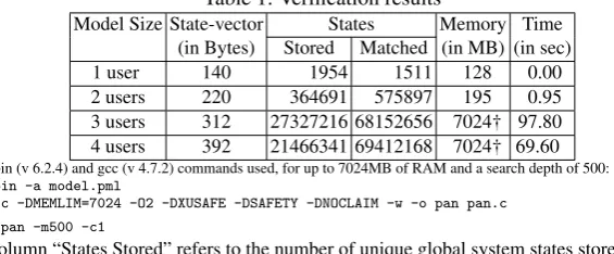
Table 1: Verification results
Model Size State-vector States Memory Time
(in Bytes) Stored Matched (in MB) (in sec)
1 user 140 1954 1511 128 0.00
2 users 220 364691 575897 195 0.95
3 users 312 27327216 68152656 7024† 97.80
4 users 392 21466341 69412168 7024† 69.60
Spin (v 6.2.4) and gcc (v 4.7.2) commands used, for up to 7024MB of RAM and a search depth of 500:
spin -a model.pml
gcc -DMEMLIM=7024 -O2 -DXUSAFE -DSAFETY -DNOCLAIM -w -o pan pan.c ./pan -m500 -c1
Column “States Stored” refers to the number of unique global system states stored in the state-space, while column “States Matched” refers to the number of states that
were revisited during the search - see:spinroot.com/spin/Man/Pan.html#L10
4.2 XCDand Architecture Realizability
All constraints in XCDarelocal, expressed on local component/role data and parame-ters. Indeed, components do not even synchronize on message emission – asynchronous channels are used to ensure that they are completely decoupled and independent.
Non-local interaction constraints, like those imposed by the glue in Fig. 2, cannot be expressed in XCD. This ensures that XCDconnectors are always realizable in a way that respects the architecture, i.e., without transforming decentralized designs to cen-tralized ones. When non-local interaction constraints are desired, they can be verified as properties of some connector or configuration.
Data themselves are encapsulated either by components or connector roles, so there are no aliasing problems, and concurrency is controlled through component ports. Each port is a concurrent unit (a monitor), thus ensuring that actions of a port are mutually exclusive to each other. As event emission/consumption and method servicing (at pro-vided ports) are atomic, architects need only guarantee (and verify) that method calling (at required ports) will not lead to data race conditions.
5
Formal Verification Analysis
The semantics of XCDdescribed in Section 4 are used to automatically transform XCD
architectures into corresponding ProMeLa models, which can be analysed by the Spin model-checker [14]. Each component instance of an architecture becomes a ProMeLa process. Instances of primitive component types follow the patterns described in Fig. 6 and 7. For composite component instances we produce again ProMeLa processes that initiate the processes of their sub-components and establish the channels that these should be using. The transformation to ProMeLa models is done through a tool that is available from the XCDweb page [22], along with other case studies and information about the XCDlanguage.
1 r o l e u s e r R o l e {
2 r e q u i r e d p o r t p v u s e r _ r { 3 i n t get ();
4 }
5 e m i t t e r p o r t p v u s e r _ e { 6 set (i n t d a t a _ a r g );
7 }
8 }
1 r o l e u s e r R o l e {
2 b o o l i n i t i a l i z e d := f a l s e; 3 r e q u i r e d p o r t p v u s e r _ r {
4 @ I n t e r a c t i o n{ w a i t s: i n i t i a l i z e d ; } 5 i n t get ();
6 }
7 e m i t t e r p o r t p v u s e r _ e { 8 @ I n t e r a c t i o n{
9 e n s u r e s: i n i t i a l i z e d := t r u e; } 10 set (i n t d a t a _ a r g );
11 } 12 }
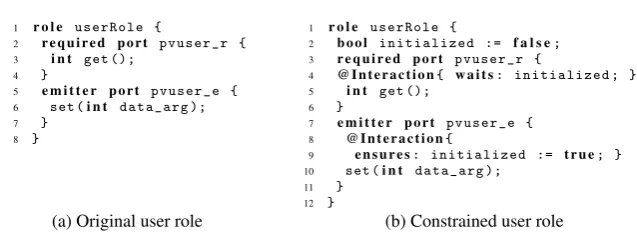
[image:15.595.137.456.109.226.2](a) Original user role (b) Constrained user role
Fig. 8: Constraining role user of connector memory2user specified in Fig. 5
Table 2: Verification results for the constrained user role of Fig. 8
Model Size State-vector States Memory Time
(in Bytes) Stored Matched (in MB) (in sec)
1 user 148 1744 1374 128 0.00
2 users 236 286735 479528 182 0.95
3 users 336 1998023 5594597 662 5.92
4 users 424 20477758 70199771 7024† 81.10
in Table 1. Its verification allowed us to quickly evaluate whether the system compo-nents behave compatibly without deadlocking. Although in some cases, the memory may go beyond the required amount for a full verification (indicated with a † in Ta-ble 1), designers can still obtain useful information about their system models and in-crease their confidence in their correctness.
In the rest of this section, we discuss some of the issues that we identified through the formal verification.
5.1 Avoiding Chaotic Behaviour through Connector Protocols
Thememory component is specified in Listing 3 with anaccepts guard stating that it will enter chaotic behaviour if it receives a call for methodgetwhen the data is not yet initialized. This is avoided through thememory2userconnector that constrains memory such that it does not receive requests for methodgetbefore the eventsetthat initializes its data. Indeed, when we remove this constraint from the memory role of the connec-tor and re-run our verification, an assertion violation error occurs identifying that the memory component has entered a chaotic behaviour.
5.2 Reducing the State Space
[image:15.595.174.424.278.352.2]constraints on user components via the user role of thememory2userconnector. When the user role is modified as shown in Fig. 8, user components cannot make requests for methodgetbefore they emit eventset. When we re-run the verification the state space is reduced as shown in Table 2, enabling us to fully verify a system with three users.
6
Conclusions
The XCD ADL supports user-defined, complex connectors, that can recursively use other connectors to model protocols and sub-protocols, in the same way as components can have sub-components. Complex connectors allow architects to increase the modu-larity of their specifications, and produce component specifications that are agnostic to their usage contexts. This increases the re-usability of component specifications and can help CBSE by permitting the development of general component specifications. It also helps with the reuse of protocol specifications as these can be specified independently of specific usage instances. Finally, it aids architectural exploration, since architects can easily replace protocols and components without having to rewrite their specifications. Many ADLs have supported connectors so far, with Wright [1] being the first one to provide formal support for them. Unfortunately, the connector structure proposed by Wright, and all those inspired from Wright ever since, permits the specification of un-realizable architectures. We showed how this can occur and presented XCD’s approach
for avoiding this issue and guaranteeing that connectors will always be realizable. The paper also presented how XCDuses and extends Design-by-Contract so as to hopefully make it easier for practitioners to use it for specifying the architectures of their systems and for communicating these architectures to others. The transformation of the XCDlanguage constructs was shown with the use of patterns of Dijkstra’s guarded com-mands that can be easily modelled with the Spin model-checker’s language ProMeLa.
Preliminary verification results showed promise, though the current tool support needs to be improved. In the future we plan to apply a number of patterns to reduce the state space of the models produced and explore ways to perform other optimizations, e.g., to reduce the state size itself.
References
1. Allen, R., Garlan, D.: A formal basis for architectural connection. ACM Trans. Softw. Eng. Methodol. 6(3), 213–249 (1997)
2. Alur, R., Etessami, K., Yannakakis, M.: Inference of message sequence charts. IEEE Trans. Software Eng. 29(7), 623–633 (2003)
3. Alur, R., Etessami, K., Yannakakis, M.: Realizability and verification of MSC graphs. Theor. Comput. Sci. 331(1), 97–114 (2005)
4. Bergstra, J.A., Ponse, A., Smolka, S.A. (eds.): Handbook of Process Algebra. Elsevier (Mar 2001)
5. Bjørner, D., Jones, C.B. (eds.): The Vienna Development Method: The Meta-Language, Lec-ture Notes in Computer Science, vol. 61. Springer (1978)
7. Chalin, P., Kiniry, J.R., Leavens, G.T., Poll, E.: Beyond assertions: Advanced specification and verification with JML and ESC/Java2. In: FMCO’05 – Formal Methods for Comp. and Obj. LNCS, vol. 4111, pp. 342–363. Springer (2006)
8. Delanote, D., Baelen, S.V., Joosen, W., Berbers, Y.: Using AADL to model a protocol stack. In: ICECCS. pp. 277–281. IEEE Computer Society (2008)
9. Dijkstra, E.W.: Guarded commands, nondeterminacy and formal derivation of programs. Commun. ACM 18(8), 453–457 (1975)
10. Feiler, P.H., Gluch, D.P., Hudak, J.J.: The Architecture Analysis & Design Language (AADL): An Introduction. Tech. rep., Software Engineering Institute (2006)
11. Garlan, D., Allen, R., Ockerbloom, J.: Architectural mismatch or why it’s hard to build sys-tems out of existing parts. In: ICSE. pp. 179–185 (1995)
12. Garlan, D., Shaw, M.: An introduction to software architecture. In: Ambriola, V., Tortora, G. (eds.) Advances in Software Engineering and Knowledge Engineering. pp. 1–39. World Scientific Publishing Company, Singapore (1993), also appears as SCS and SEI technical reports: CMU-CS-94-166, CMU/SEI-94-TR-21, ESC-TR-94-021.
13. Hoare, C.A.R.: An axiomatic basis for computer programming. Commun. ACM 12(10), 576–580 (1969)
14. Holzmann, G.J.: The SPIN Model Checker - Primer and reference manual. Addison-Wesley (2004)
15. Issarny, V., Bennaceur, A., Bromberg, Y.D.: Middleware-layer connector synthesis: Beyond state of the art in middleware interoperability. In: Bernardo, M., Issarny, V. (eds.) SFM. Lecture Notes in Computer Science, vol. 6659, pp. 217–255. Springer (2011)
16. Ivers, J., Clements, P., Garlan, D., Nord, R., Schmerl, B., Silva, J.R.O.: Documenting com-ponent and connector views with UML 2.0. Tech. Rep. CMU/SEI-2004-TR-008, Software Engineering Institute (Carnegie Mellon University) (2004)
17. Luckham, D.C.: Rapide: A language and toolset for simulation of distributed systems by partial orderings of events. Tech. rep., Stanford University, Stanford, CA, USA (1996) 18. Magee, J., Kramer, J.: Dynamic structure in software architectures. In: SIGSOFT FSE. pp.
3–14 (1996)
19. Malavolta, I., Lago, P., Muccini, H., Pelliccione, P., Tang, A.: What industry needs from architectural languages: A survey. IEEE Trans. Software Eng. 39(6), 869–891 (2013) 20. Medvidovic, N., Taylor, R.N.: A classification and comparison framework for software
ar-chitecture description languages. IEEE Trans. Software Eng. 26(1), 70–93 (2000) 21. Meyer, B.: Applying “Design by Contract”. IEEE Computer 25(10), 40–51 (1992)
22. Ozkaya, M.: XCDwebsite.http://www.soi.city.ac.uk/~abdz276/xcd.html(2013)
23. Perry, D.E., Wolf, A.L.: Foundations for the study of software architecture. SIGSOFT Softw. Eng. Notes 17(4), 40–52 (Oct 1992)
24. Plasil, F., Visnovsky, S.: Behavior protocols for software components. IEEE Trans. Software Eng. 28(11), 1056–1076 (2002)
25. Schmidt, H., Poernomo, I., Reussner, R.: Trust-by-contract: Modelling, analysing and pre-dicting behaviour of software architectures. J. Integr. Des. Process Sci. 5(3), 25–51 (Aug 2001)
26. Schreiner, D., G¨oschka, K.M.: Explicit connectors in component based software engineering for distributed embedded systems. In: Proceedings of the 33rd conference on Current Trends in Theory and Practice of Computer Science. pp. 923–934. SOFSEM ’07, Springer-Verlag, Berlin, Heidelberg (2007)
27. Tripakis, S.: Undecidable problems of decentralized observation and control. In: Proc. of the
40thIEEE Conf. on Decision and Control. vol. 5, pp. 4104–4109. IEEE, Orlando, FL, USA
(Dec 2001)
![Fig. 1: A nuclear power plant [2]](https://thumb-us.123doks.com/thumbv2/123dok_us/1514548.104066/4.595.138.460.122.202/fig-a-nuclear-power-plant.webp)