Simulation study of a passive plasma beam dump using varying plasma
density
KieranHanahoe,1,2,a)GuoxingXia,1,2MohammadIslam,1,2YangmeiLi,1,2 €
OznurMete-Apsimon,3,2BernhardHidding,4,2and JonathanSmith5 1
School of Physics and Astronomy, University of Manchester, Oxford Road, Manchester M13 9PL, United Kingdom
2
Cockcroft Institute, Sci-Tech Daresbury, Keckwick Lane, Daresbury, Cheshire WA4 4AD, United Kingdom 3
Department of Engineering, Lancaster University, Bailrigg, Lancaster LA1 4YW, United Kingdom 4
Department of Physics, University of Strathclyde, Richmond Street, Glasgow G1 1XQ, United Kingdom 5
Tech-X UK Ltd., Sci-Tech Daresbury, Keckwick Lane, Daresbury, Cheshire WA4 4FS, United Kingdom
(Received 22 November 2016; accepted 10 February 2017; published online 27 February 2017)
A plasma beam dump uses the collective oscillations of plasma electrons to absorb the kinetic energy of a particle beam. In this paper, a modified passive plasma beam dump scheme is proposed using either a gradient or stepped plasma profile to maintain a higher decelerating gradient compared with a uniform plasma. The improvement is a result of the plasma wavelength change preventing the re-acceleration of low energy particles. Particle-in-cell simulation results show that both stepped and gradient plasma profiles can achieve improved energy loss compared with a uni-form plasma for an electron bunch of parameters routinely achieved in laser wakefield acceleration.
Published by AIP Publishing.[http://dx.doi.org/10.1063/1.4977449]
I. INTRODUCTION
The safe operation of a particle accelerator requires that the beam be disposed of once it has been used. This is usu-ally achieved using a dense material such as a metal, graph-ite, or water. Such a conventional beam dump can stop even a very high energy electron beam in a relatively short dis-tance. For example, the Large Electron-Positron Collider (LEP) used a 2 m long aluminium dump to stop a 100 GeV electron beam1and the proposed water-based dump for the International Linear Collider (ILC)2,3is designed to stop a 500 GeV beam in 11 m. However, the high density of the stopping medium and high power of the beam led to a num-ber of disadvantages for a conventional dump. Both proton and electron beams lead to the production of radionuclides in the stopping material.4,5 The dump must be capable of absorbing the high power of the beam (18 MW for the ILC) in a small volume, leading to high power density cooling requirements and high temperatures and pressures.3The ILC beam dump design would operate at 10 bar and at a maxi-mum water temperature of 155C. In the case of a water dump, decomposition generates hydrogen and oxygen gas which must be removed.2,6 In addition, structural materials may suffer radiation damage and lose strength, a concern for pressure vessels and windows.6,7 These considerations lead to a conventional beam dump being substantially larger than the simple stopping power may suggest. For instance, the proposed ILC dump will require a pumping station, water tower, catalytic hydrogen-oxygen recombiner, and deionizer sited above ground, connected via pipes to the dump loca-tion. A sump is also required to collect any radioactive water that may leak from the dump and ancillary equipment.3
One proposed alternative to a high density beam dump uses a beam pipe filled with a noble gas at atmospheric pres-sure, surrounded by iron cladding. With a length of 1000 m the power deposited per unit length is greatly reduced.8Heat can be dissipated by a simple water cooling jacket at atmo-spheric pressure and radio-activation is reduced compared with the baseline ILC design. However, the disadvantage of this scheme is the extremely long length required to stop a high energy beam and the associated costs of providing space for such a dump.
Another dump scheme, focused on in this paper, uses a plasma wakefield to decelerate a bunch at a high gradient.9 The plasma beam dump minimizes radio-activation by oper-ating at a low density even compared with a gas dump, and potentially allows for the recovery of some of the beam energy as electricity rather than dissipation as heat.9 The high decelerating gradients achievable with high density ultrashort bunches such as those produced by laser wakefield acceleration make plasma beam dumps suitable to comple-ment compact accelerators with compact beam disposal.
In this paper, SectionIIcompares the plasma beam dump with the conventional beam dump. Section II discusses the use of modified plasma profiles to improve the performance of a passive plasma beam dump and Section III presents particle-in-cell (PIC) simulation results for a range of plasma beam dump parameters using fixed beam parameters.
II. PLASMA BEAM DUMP AND CONVENTIONAL BEAM DUMP COMPARED
The stopping power, i.e., the average loss of energy T
with distance, of an electron in a neutral medium depends on its energy. At high energies, losses are dominated by brems-strahlung. The critical energyTcmay be defined as the energy at which losses due to bremsstrahlung are equal to losses due
a)
to other factors, e.g., ionization. The critical energy in MeV is approximated by Tc¼ ð800 MeVÞ=ðZþ1:2Þwhere Z is the atomic number of the stopping material.10For high-Z materi-als such as lead or copper, bremsstrahlung dominates at any relevant energy. For lowerZmaterials such as water, brems-strahlung is dominant above a few hundred MeV. The stop-ping power due to radiation is given by9
dT
dx¼Za
4e4ne
mc2 ðc1Þln 183Z
1 3
; (1)
whereais the fine structure constant,mis the incident parti-cle mass,neis the electron density of the stopping material,
eis the elementary charge,cis the relativistic gamma factor, andcis the speed of light, with all quantities in CGS units. As long as bremsstrahlung is dominant, the stopping power is linearly proportional to the kinetic energy of the incident particles,T¼ ðc1Þmc2.
In a plasma medium, an electron bunch is decelerated by collective oscillations of the electrons in the plasma. The plasma wakefield may be excited by the beam itself in a pas-sive beam dump, or excited by a laser pulse in an active beam dump. The plasma may be preformed or, if the driver is of sufficient intensity, be a neutral gas ionized by the driver itself.11A field-ionized plasma would make the pas-sive dump simple and reliable. A paspas-sive beam dump has recently been demonstrated experimentally over a short dis-tance using a laser-accelerated bunch.12,13 It has previously been shown using simulations that for typical Laser Wakefield Accelerator (LWFA) bunch parameters, the initial stopping power of a passive plasma beam dump is indepen-dent of initial beam energy.9
The passive dump does however suffer from a major limi-tation of being unable to decelerate the head of the bunch due to the finite response time of the plasma. This problem can be addressed by the active beam dump, in which the beam is decelerated by the wakefield of a laser pulse.14An active beam dump however relies on the provision of a laser pulse and accu-rate synchronization. Without either the dump would fail to stop the beam and a backup dump would need to be available.
Recent experimental results have shown that an electron beam can be decelerated by a plasma when initially offset transversely from the plasma column.15The electron beam is attracted by the charge imbalance created by the beam’s trans-verse fields. In a plasma beam dump employing a pre-formed plasma, this phenomenon would allow the requirements on alignment of the bunch and plasma column width to be relaxed, potentially improving the reliability of the dump.
The highest decelerating gradients for a given plasma density can be achieved in the non-linear regime, where the bunch density exceeds the plasma density. The limit on the maximum decelerating gradient is the wave-breaking field
Ewb, which depends on the electron plasma frequencyxp
Ewb¼
mecxp
e ; (2)
xp¼ e
2n p 0me
1 2
; (3)
whereme is the electron mass,0is the permittivity of free space, andnp is the plasma electron density, and all quanti-ties are in SI units.
The limit of the wave-breaking field for a plasma den-sity of 1024m3can be compared with a copper beam dump for an electron beam of 1 GeV. Equation(1)gives an initial average decelerating gradient of 5:1 GeV m1 compared with a wave-breaking field of 96 GV m1. The actual decel-erating gradient that can be achieved in a plasma depends on the properties of the electron bunch. A short bunch with den-sity higher than the plasma denden-sity can achieve a gradient approaching the wave-breaking limit as has been demon-strated experimentally.11,16–18
Very short, high density bunches are routinely produced by laser wakefield acceleration,19–22 making plasma beam dumps well suited to pairing with laser plasma accelerators. Long bunches can drive large wakefields by self-modulation, potentially widening the scope of applicability of the plasma beam dump. Recent experiments have provided an initial indication of self-modulation in a long electron beam.23 Such long bunches are however not studied in this paper. Experiments have also shown that positron bunches can drive strong plasma wakefields,18 indicating that a plasma beam dump would also be applicable to a positron beam.
III. PLASMA BEAM DUMP SCHEMES
The simplest version of a plasma beam dump is a uni-form plasma into which the particle bunch to be decelerated propagates. The head of the bunch will experience no decel-erating field, while some part of the bunch will experience a maximum decelerating field. After some time the part of the bunch that experiences the maximum field will become non-relativistic and will fall behind the rest of the bunch until it reaches an accelerating region of the wakefield. The portion of the bunch will then absorb energy from the wakefield and be re-accelerated. This leads to the rate of energy loss of the bunch dramatically decreasing after a saturation length Lsat, as a substantial proportion of the energy lost is reabsorbed. The saturation length for a beam of initial energy T0 is approximately the propagation length at which the maximum decelerating gradientEdecdecelerates a portion of the beam to non-relativistic velocity
Lsat
T0
eEdec
: (4)
Since the decelerating gradient of a passive plasma beam dump depends on the bunch dimensions but not on the initial energy, a higher energy beam can be dumped using a corre-spondingly longer plasma. As a higher energy beam will remain highly relativistic for longer as it loses energy, a greater fraction of the initial energy can be absorbed before dephasing causes the decelerating gradient to fall.
achieves the same result using a plasma-only decelerating medium may be attractive.
As an alternative to the use of foils to absorb low energy particles, the decelerated particles can be removed from the accelerating region of the wakefield by defocusing. This can be achieved by increasing the plasma density once the bunch has travelled over the saturation length. The plasma wave-lengthkpis related to the plasma electron densitynpby
kp¼2pc 0me e2n
p
1 2
3:3107=pffiffiffiffiffinp; (5)
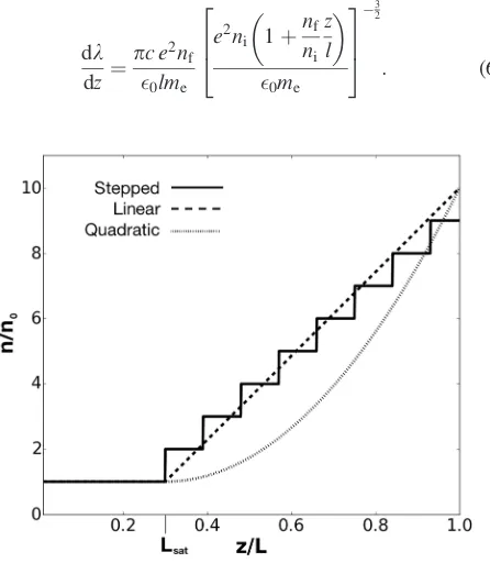
where all quantities are in SI units. As the density increases the plasma wavelength decreases, effectively shifting the bunch within the wakefield. Half of one plasma wavelength behind the drive bunch is the region of highest on-axis elec-tron density. If the plasma density is increased, decelerated particles will pass through a strong defocusing region and be removed from the axis. This will prevent their re-acceleration. For a stepped plasma, the change in plasma wavelength is instantaneous and the decelerated particles do not need to pass through the accelerating region. For a gradual plasma density increase the decelerated particles will gain energy in the accelerating region prior to being defocused. Figure 1 shows a diagram of the stepped and gradient plasma density schemes. The rate of change with position of the plasma wavelength can be calculated for a given plasma profile, by taking the derivative of kp (Equation (5)) with respect to z. For a linearly increasing plasma density from initial density ni to a final density nf over a lengthl
dk dz¼
pc e2n f 0lme
e2ni 1þ
nf
ni
z l
0me
2 6 4
3 7 5 3
2
: (6)
In the linear regime, the defocusing region is located kp=4 behind the maximum decelerating region. The propaga-tion distanceDzover which the plasma wavelength changes by 1/4 can be estimated assuming that the rate of change of plasma wavelength is constant, and the energy gainDTis the average accelerating fieldEaccmultiplied by the propagation distance
DT ¼EaccDz¼Eacc k0
4 dk dz
1
; (7)
[image:3.607.364.508.329.724.2]wherek0is the initial plasma wavelength at a given positionz. The more rapid the change in plasma density, the less energy will be gained by the decelerated particles; however, the den-sity has to remain low enough to be achievable and to gener-ate a high decelerating field. In this study the density was increased by a factor of ten over the plasma length. Linear and quadratic plasma density changes were considered. A quadratic density profile was found to reduce the expected re-acceleration over a larger portion of the plasma length com-pared with a linear ramp.
FIG. 1. Plot illustrating stepped, linear gradient, and quadratic gradient plasma density schemes. The density is constant over the saturation length Lsatand then increases over the remaining lengthl. The total plasma length
isL¼Lsatþl. For the stepped scheme, the gradient increases by a fixed
amount for each step, while for the gradient schemes the density increases to ten times its initial value.
[image:3.607.65.288.443.699.2]IV. SIMULATION RESULTS
Two-dimensional simulations of passive beam dump schemes were carried out using the explicit particle-in-cell (PIC) code VSim.24Bunch parameters were chosen to repre-sent a bunch that can be generated routinely by laser wake-field acceleration.19–22 The bunch has an rms length of
7.5lm, rms radius of 20lm, and charge of 100 pC. The total energy of the bunch is 0:025 J corresponding to a bunch which may be generated by a modest laser pulse of 0:25 J assuming 10% laser to bunch efficiency.25 A moderate energy of 250 MeV allows the simulation length to be kept short. A 25 cm plasma length allows the deceleration to satu-rate and for modified density schemes to be studied. An ini-tial plasma densityni of 21023m3 was used, for a range of step lengths and for linear and quadratically increasing plasma density after the saturation length. The initial den-sity corresponds to a plasma wavelength of 75lm. For the gradient plasma schemes the density was increased by a factor of 10 starting from the saturation length and ending at the end of the plasma. The step schemes increased the plasma density by ni for each step. The step length refers to the length of the flat plasma density between each step. The plasma and beam density and electric fields at
z¼5 cm are shown in Figure2, before any plasma density change occurs. The peak decelerating field of approxi-mately 3 GV m1 gives a calculated saturation length of 8.3 cm. Preliminary simulations showed that saturation in fact occurs at approximately 10.5 cm and this value was used in subsequent simulations.
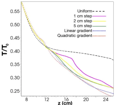
[image:4.607.79.264.58.228.2]Figure3shows the change in total beam energy for dif-ferent dump schemes. The gradient scheme proved to pro-vide the greatest energy loss over 25 cm. Figure 4 shows the longitudinal phase space for a uniform plasma and a 1 cm stepped plasma profile. In each plot the bunch has FIG. 3. Energy loss with distance for uniform, stepped, and gradient
[image:4.607.68.282.399.718.2]plasma density profiles. Prior to approximately z¼10 cm all profiles show the same constant decelerating gradient, so this region is omitted from the plot. The vertical axis gives total beam energy as a fraction of initial beam energy.
FIG. 4. Longitudinal phase space histogram atz¼16:3 cm for a uniform plasma (a) and a linear gradient plasma profile (b). The energy scale corre-sponds toc=mec2and as such is not accurate for non-relativistic velocities.
The color scale gives the sum of macroparticle weight for each bin.
[image:4.607.326.542.413.724.2]propagated 16:3 cm in the plasma, some distance beyond the saturation length of approximately 10 cm. It can be seen that significantly less charge is re-accelerated in the case of the gradient profile. In the regionzct<30lm, outside the extent of the initial bunch, at z¼16:3 cm there was found to be 25 pC of charge re-accelerated to greater than 30 MeV. This compares with only 0:6 pC in the gradient plasma density case. The higher energy portion of the bunch located at zct¼ 20lm is the tail of the bunch which experiences a lower decelerating gradient than the central part. Figure5shows a plot of energy and transverse position at the same propagation distance. The lowest energy part of the bunch has been defocused while the higher energy particles have not been affected. The defo-cused particles are limited to less than approximately 50 MeV. The evolution of the longitudinal phase space for a linear plasma density increase is shown in Figure 6. It can be seen that at z¼10 cm (Figure6(c)), before the start of the density increase, some of the decelerated particles have started to be re-accelerated. Once the density increase com-mences, the re-accelerated particles are lost (Figures
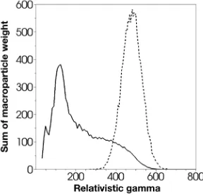
6(d)–6(f)). A comparison of the initial and final energy spectra for the linear ramp case is shown in Figure 7. Although the peak energy of the bunch remains largely unchanged, the intensity of particles at the initial central energy has been reduced by a factor of 10. The relativisticc at the peak intensity of the final bunch corresponds to an energy of approximately 75 MeV.
V. CONCLUSION AND OUTLOOK
[image:5.607.65.546.55.386.2]Simulation results show that a short, moderate charge electron bunch can lose a large fraction of its energy in a 25 cm plasma. Stepped and gradient plasma profiles are capable of improving energy loss and provide an alternative to the previously proposed foil scheme. Gradient plasma pro-files were found to be most effective in improving energy loss; however, there was relatively little difference between the linear and quadratic plasma profiles. The largest energy loss achieved in simulations was approximately 75% of the initial beam energy. The advantage of the gradient scheme FIG. 6. Evolution of the longitudinal phase space for a plasma with a linear density increase. Phase space atz¼(a) 0, (b) 5, (c) 10, (d) 15, (e) 20, and (f) 25 cm are shown. Thexandyscales for each plot are the same, while the color scales are not.
[image:5.607.363.507.587.725.2]suggests that the energy gain of non-relativistic particles while the plasma wavelength changes is not significant for the parameters used. However, this may not be the case when bunch parameters are such that the accelerating gradient is very large. The achievability of the modified plasma density profiles will depend on the technology used for the source, which will in turn depend on the beam and plasma parameters. Such considerations will be important if such a passive plasma beam dump is to be experimentally tested in the future.
Plasma beam dumps show great promise both in provid-ing compact deceleration to complement high-gradient novel accelerators and in reducing the complexity of beam dumps in conventional accelerators. Although passive plasma beam dumps are not capable of decelerating the head of the bunch, the rapid reduction in total beam energy would allow for a conventional beam dump to absorb the remaining energy with greatly reduced radio-activation and cooling requirements.
ACKNOWLEDGMENTS
This work was supported by the Cockcroft Institute Core Grant and the STFC. The authors gratefully acknowledge the computing time granted on the supercomputer JURECA at J€ulich Supercomputing Centre (JSC).
1E. Carlier, U. Jansson, R. Jung, V. Mertens, S. Peraire, M. Ross, G. Schr€oder, G. R. Stevenson, E. B. Vossenberg, E. Weisse, and J. M. Zazula, in Proceedings of the 4th European Particle Accelerator Conference (1994), p. 2494.
2C. Adolphsen, M. Barone, B. Barish, K. Buesser, P. Burrows, J.
Carwardine, J. Clark, H. Mainaud Durand, G. Dugan, E. Elsen, A. Enomoto, B. Foster, S. Fukuda, W. Gai, M. Gastal, R. Geng, C. Ginsburg, S. Guiducci, M. Harrison, H. Hayano, K. Kershaw, K. Kubo, V. Kuchler, B. List, W. Liu, S. Michizono, C. Nantista, J. Osborne, M. Palmer, J. McEwan Paterson, T. Peterson, N. Phinney, P. Pierini, M. Ross, D. Rubin, A. Seryi, J. Sheppard, N. Solyak, S. Stapnes, T. Tauchi, N. Toge, N. Walker, A. Yamamoto, and K. Yokoya, “ILC technical design report vol. 3, part II—Baseline design,” Technical Report No. ILC-REPORT-2013-040 (Linear Collider Collaboration, Batavia, IL, USA, 2013).
3
P. Satyamurthy, P. Rai, V. Tiwari, K. Kulkarni, J. Amann, R. G. Arnold, D. Walz, A. Seryi, T. Davenne, O. Caretta, C. Densham, and R. Appleby, Nucl. Instrum. Methods Phys. Res., Sect. A679, 67 (2012).
4D. Schumann, J. Neuhausen, J. Eikenberg, M. R€uthi, M. Wohlmuther,
P. W. Kubik, H. A. Synal, V. Alfimov, G. Korschinek, G. Rugel, and T. Faestermann,Radiochim. Acta97, 123 (2009).
5A. Leuschner and K. Tesch, “The residual radioactivity of a water-copper
beam dump for the TESLA test facility,” Technical Report No. DESY D3-92 (Deutsches Elektronen-Synchrotron, Hamburg, Germany, 1998). 6
D. R. Walz, J. Jurow, and E. L. Garwin,IEEE Trans. Nucl. Sci.12, 867 (1965). 7K. Nordlund, A. Sand, F. Granberg, S. J. Zinkle, R. Stoller, R. S. Averback, T. Suzudo, L. Malerba, F. Banhart, W. J. Weber, F. Willaime,
S. Dudarev, and D. Simeone, “Primary radiation damage in materials,” Technical Report No. NEA/NSC/DOC(2015)9 (OECD-NEA, Paris, France, 2015).
8A. Leuschner, “Another crazy idea of an LC dump compared to the water
dump design,” LC-ABD Dump Meetings (2005). 9
H. C. Wu, T. Tajima, D. Habs, A. W. Chao, and J. Meyer-ter Vehn,Phys. Rev. Spec. Top. Accel. Beams13, 101303 (2010).
10
Particle Data Group,Phys. Lett. B667, 261 (2008). 11
M. Hogan, T. O. Raubenheimer, A. Seryi, T. Katsouleas, C. Huang, W. Lu, W. An, K. A. Marsh, W. B. Mori, C. E. Clayton, and C. Joshi,New J. Phys.12, 055030 (2010).
12
S. Chou, “Investigation of electron acceleration and deceleration in plasmas,” Ph.D. thesis, Ludwig-Maximilian University of Munich, Munich, Germany, 2015.
13
S. Chou, J. Xu, K. Khrennikov, D. E. Cardenas, J. Wenz, M. Heigoldt, L. Hofmann, L. Veisz, and S. Karsch,Phys. Rev. Lett.117, 144801 (2016). 14A. Bonatto, C. B. Schroeder, J. L. Vay, C. G. R. Geddes, C. Benedetti, E.
Esarey, and W. P. Leemans,Phys. Plasmas22, 083106 (2015). 15
E. Adli, C. Lindstrøm, J. Allen, C. Clarke, J. Frederico, S. Gessner, S. Green, M. Hogan, M. Litos, B. O’Shea, V. Yakimenko, W. An, C. Clayton, K. Marsh, W. Mori, C. Joshi, N. Vafaei-Najafabadi, S. Corde, and W. Lu,New J. Phys.18, 103013 (2016).
16
I. Blumenfeld, C. E. Clayton, F. J. Decker, M. J. Hogan, C. Huang, R. Ischebeck, R. Iverson, C. Joshi, T. Katsouleas, N. Kirby, W. Lu, K. A. Marsh, W. B. Mori, P. Muggli, E. Oz, R. H. Siemann, D. Walz, and M. Zhou,Nature445, 741 (2007).
17M. Litos, E. Adli, W. An, C. I. Clarke, C. E. Clayton, S. Corde, J. P.
Delahaye, R. J. England, A. S. Fisher, J. Frederico, S. Gessner, S. Z. Green, M. J. Hogan, C. Joshi, W. Lu, K. A. Marsh, W. B. Mori, P. Muggli, N. Vafaei-Najafabadi, D. Walz, G. White, Z. Wu, V. Yakimenko, and G. Yocky,Nature515, 92 (2014).
18
S. Corde, E. Adli, J. M. Allen, W. An, C. I. Clarke, C. E. Clayton, J. P. Delahaye, J. Frederico, S. Gessner, S. Z. Green, M. J. Hogan, C. Joshi, N. Lipkowitz, M. Litos, W. Lu, K. A. Marsh, W. B. Mori, M. Schmeltz, N. Vafaei-Najafabadi, D. Walz, V. Yakimenko, and G. Yocky,Nature524, 442 (2015).
19S. Karsch, J. Osterhoff, A. Popp, T. P. Rowlands-Rees, Z. Major, M.
Fuchs, B. Marx, R. H€orlein, K. Schmid, L. Veisz, S. Becker, U. Schramm, B. Hidding, G. Pretzler, D. Habs, F. Gr€uner, F. Krausz, and S. M. Hooker, New J. Phys.9, 415 (2007).
20
J. Osterhoff, A. Popp, Z. Major, B. Marx, T. P. Rowlands-Rees, M. Fuchs, M. Geissler, R. H€orlein, B. Hidding, S. Becker, E. A. Peralta, U. Schramm, F. Gr€uner, D. Habs, F. Krausz, S. M. Hooker, and S. Karsch, Phys. Rev. Lett.101, 085002 (2008).
21
A. Buck, J. Wenz, J. Xu, K. Khrennikov, K. Schmid, M. Heigoldt, J. M. Mikhailova, M. Geissler, B. Shen, F. Krausz, S. Karsch, and L. Veisz, Phys. Rev. Lett.110, 185006 (2013).
22
V. Malka, in Proceedings of the 4th International Particle Accelerator Conference(2013), p. 11.
23E. Adli, V. B. Olsen, C. Lindstrøm, P. Muggli, O. Reimann, J. Vieira, L.
Amorim, C. Clarke, S. Gessner, S. Green, M. Hogan, M. Litos, B. O’Shea, V. Yakimenko, C. Clayton, K. Marsh, W. Mori, C. Joshi, N. Vafaei-Najafabadi, and O. Williams,Nucl. Instrum. Methods Phys. Res., Sect. A 829, 334 (2016).
24
C. Nieter and J. Cary,J. Comput. Phys.196, 448 (2004).