Prediction, Detection, and Observation of Rotorcraft Pilot
Couplings
Thesis submitted in accordance with the requirements of the University of Liverpool for the degree of Doctor in Philosophy
by
Michael Graham Jones
Abstract
Unmasking Aircraft and Rotorcraft Pilot Couplings (A/RPC) prior to vehicle entry into service has been a long standing challenge in the Aerospace Industry. A/RPCs, often only exposed through unpredictable or very specific circumstances have arisen throughout the history of manned powered flight, and have required short-term ‘fixes’ to ensure system safety. One of the reasons for this occurrence is th lack of detailed practice regarding the prediction and detection of RPCs prior to full-scale testing. Of-ten in simulation, A/RPCs are only investigated once problems have been experienced during other aircraft qualification activities. This is a particular issue for the rotor-craft community, where system sophistication is ‘catching-up’ with their fixed-wing counterparts.
This research helps to extend the state-of-art knowledge surrounding the exposure of RPCs prior to any catastrophic occurrences, through the introduction of novel tools for use both in the rotorcraft design process and beyond. Using key definitions and findings from previous research efforts, objective and subjective measures have been developed for use in both real-time piloted flight and for pre- or post-flight analysis. These tools have been designed to compliment one another, in a process that should reduce the susceptibility to RPC in future rotorcraft.
Novel tools developed have been tested through real-time piloted simulation, with results allowing RPC susceptibility boundaries and regions to be identified. Application of all tools developed, both subjective and objective, have been validated through comparison with existing methods.
Acknowledgement
I wish to thank everyone who has assisted me in any way during the duration of this
PhD study.
Further mentions however must start by thanking my supervisor, Dr Mike Jump, who has been a constant support during the completion of this work. One day I will repay him by getting all of the right words in the correct order.
Since the start of this work, I have had the chance to meet many learned individuals, who have all assisted me in my quest. I have been lucky to work alongside fellow PhD candidate Deniz Yilmaz, who has been a great support during work. His assistance with experimental work contained within this thesis cannot be overlooked. I had the chance act as a witness at his wedding, and on numerous occasions he has let me stay in his ‘one star’ hotel.
I must thank all fellow FS&T, particularly Emma, Garnet and Sophie. All have moved on to pastures new, but were a great support during my work. Also to those who still remain, including Philip, Mark, and Tom Fell. Particular thanks also go to the support of Dr Linghai Lu and Prof. Gareth Padfield, who both offered helpful support and advice through this work.
I would like to thank all partners in the ARISTOTEL project; particularly ‘the un-professional pilots’ Vinny, Giuseppe, and Pierangelo. Furthermore, Olaf Stroosma, Marilena Pavel, and Binh Dang Vu have provided significant assistance with technical work completed during the project. I would also like to thank the Professional pilots, as without their help I would have been stuck with only the ‘un-professional pilots’. I have been lucky to have the support of my family whilst in Liverpool. Thanks to all of them for their encouragement and assistance during my studies. Soon young Alex and Matthew will be undertaking their PhD’s!
the help I have needed to get to this stage.
Both of my Grandparents, Blanche and Arthur, have been constant support during my life, and have encouraged me to always think positively. I encourage everyone to do to the same.
Contents
Abstract i
Acknowledgement iii
Contents iv
Publications xii
Nomenclature xiv
Acronyms xv
1 Introduction 1
1.1 What Are Aircraft/Rotorcraft Pilot Couplings? . . . 1
1.1.1 Classification of Aircraft/Rotorcraft Pilot Couplings . . . 4
1.1.2 Problems Unmasking Aircraft/Rotorcraft Pilot Couplings . . . . 7
1.2 The ARISTOTEL Project . . . 10
1.3 Thesis Objective . . . 11
1.4 Thesis Structure . . . 12
1.5 Originality and Novelty . . . 13
2.1 Overview . . . 14
2.2 Prediction of A/RPCs . . . 16
2.3 Protection against A/RPCs . . . 23
2.3.1 Suppression . . . 24
2.3.2 Compensation . . . 25
2.3.3 Detection . . . 31
2.4 Assessment of A/RPCs . . . 35
2.4.1 Subjective Methods . . . 35
2.4.2 Tasks . . . 42
2.5 Summary of Review . . . 44
2.6 Research Questions . . . 45
3 Experimental Set-up 46 3.1 Outline . . . 46
3.2 Vehicle Modelling . . . 46
3.2.1 Nonlinear Vehicle for Real-Time Simulation Model . . . 47
3.2.2 Model Validation . . . 50
3.3 PIO Susceptibility Using Current Tools . . . 55
3.3.1 Predictions Using Bandwidth Phase Delay . . . 55
3.3.2 Predictions Using OLOP . . . 57
3.4 Simulation Devices . . . 62
3.5 Mission Task Development . . . 63
3.6 Pilots . . . 66
4 A New Criterion for Detection of RPCs 70
4.1 Objective . . . 70
4.2 Overview of Pilot-Induced Oscillation Detection Methods . . . 71
4.2.1 Real-Time Oscillation VERifier (ROVER) . . . 71
4.2.2 Pilot-Inceptor Workload . . . 73
4.3 Real-Time Phase-Aggression Criterion . . . 75
4.4 Preliminary PAC Investigations . . . 79
4.4.1 Identification of Pilot-Induced Oscillations . . . 81
4.4.2 Application of ROVER . . . 83
4.4.3 Application of PAC Criterion . . . 88
4.4.4 PAC correlation and consistency . . . 99
4.5 Validation of Boundaries through Single Axis Flying Task . . . 103
4.6 Validation of Boundaries During Multi-axis Flying Tasks . . . 107
4.6.1 Precision Hover Task . . . 107
4.6.2 Application of Longitudinal Boundary . . . 111
4.6.3 Identification of Lateral Boundary . . . 116
4.6.4 Correlation between Pilot Subjective and Phase-Aggression . . . 120
4.7 Validation of Boundaries with Independent Data Source . . . 121
4.8 Integration of Real-Time PAC Coding . . . 125
4.9 Summary of Chapter 4 . . . 129
5 The Development of Prediction Tools for RPCs 130 5.1 Objective . . . 130
5.2 Transition from Detection tool to Prediction tool . . . 130
5.2.2 C-PRE-PAC Method . . . 134
5.3 O-PRE-PAC Linear Examples . . . 137
5.3.1 Calculation of PIO Metrics . . . 138
5.3.2 Calculation of PIO envelope . . . 142
5.3.3 Influence of Control Gearing . . . 143
5.4 Parametric Sweeps using C-PRE-PAC . . . 145
5.4.1 Observation of PAC Based on Rate Limit Boundaries . . . 149
5.5 Case Study Examples . . . 151
5.6 Validation of PRE-PAC Criteria . . . 160
5.6.1 O-PRE-PAC Prediction . . . 160
5.6.2 C-PRE-PAC Prediction . . . 161
5.7 Summary of Chapter 5 . . . 169
6 A New Subjective Method to Assess A/RPCs 170 6.1 Objectives . . . 170
6.2 Recap of Previous A/RPC Scales . . . 170
6.3 Critique of ‘the PIO Tendency Rating Scale’ . . . 171
6.3.1 Subjective Scale with Limited Subjectivity . . . 172
6.3.2 Severity: Poor Descriptors . . . 173
6.3.3 Question of Divergence . . . 174
6.3.4 The Three Point Scale . . . 174
6.3.5 Task Dependency . . . 175
6.4 Solution: A Novel Adverse Pilot Coupling Scale . . . 175
6.4.1 Development . . . 175
6.5.1 Experimental Setup . . . 181
6.5.2 Task . . . 182
6.5.3 Results . . . 184
6.5.4 Comparison . . . 190
6.6 Summary of Chapter 6 . . . 191
7 Simulation Case Study 193 7.1 Objective . . . 193
7.2 Process . . . 193
7.2.1 Vehicle . . . 195
7.2.2 Requirements . . . 196
7.3 Prediction - Using PRE-PAC . . . 198
7.4 Results . . . 200
7.4.1 Roll Step Results . . . 200
7.4.2 Precision Hover Results . . . 209
7.5 Correlation . . . 214
7.5.1 Roll Step Correlation . . . 216
7.5.2 Precision Hover Correlation . . . 219
7.6 Overall Observations . . . 221
7.7 Summary of Chapter 7 . . . 222
8 Conclusions and Recommendations 223 8.1 Conclusions . . . 223
8.2 Recommendations . . . 225
A.1 Bo105 Reference Data . . . 239
B Mission Task Elements 242 B.1 Accel-Decel . . . 242
B.1.1 Objectives . . . 242
B.1.2 Description of Manoeuvre . . . 242
B.1.3 Description of Test Course . . . 243
B.2 Lateral Reposition/Sidestep . . . 243
B.2.1 Objectives . . . 243
B.2.2 Description of Manoeuvre . . . 244
B.3 Precision Hover . . . 244
B.3.1 Objectives . . . 244
B.3.2 Description of Manoeuvre . . . 245
B.3.3 Performance Standards . . . 245
B.4 Vertical Manoeuvre . . . 246
B.4.1 Objectives . . . 246
B.4.2 Description of Manoeuvre . . . 246
B.4.3 Description of Test Course . . . 246
B.4.4 Performance Standards . . . 247
B.5 Slalom . . . 247
B.5.1 Objectives . . . 247
B.5.2 Description of Manoeuvre . . . 248
B.5.3 Description of Test Course . . . 248
B.5.4 Performance Standards . . . 248
B.6.1 Objectives . . . 249
B.6.2 Description of Manoeuvre . . . 249
B.6.3 Description of Test Course . . . 249
B.6.4 Performance Standards . . . 250
B.7 Roll Tracking . . . 250
B.8 Pitch Tracking . . . 251
B.8.1 Objectives . . . 251
B.8.2 Description of Manoeuvre . . . 251
B.8.3 Performance Standards . . . 252
C Detailed Subjective Ratings 253 D PAC Correlation 268 D.1 Roll Step . . . 268
Publications
The following are the publications that have included the work presented within this thesis.
Journal Publications
Jones,M., Jump,M.,“New Methods to Subjectively and Objectively Evaluate Adverse
Pilot Couplings,” Journal of the American Helicopter Society, Vol.60, No.1, 2015
doi:10.4050/JAHS.60.011003
Jones,M., Jump,M., Lu,L.,“Development of the Phase-Aggression Criterion for
De-tection of Rotorcraft Pilot Couplings,” Journal of Guidance, Control, and Dynamics,
AIAA, Vol.36, No.1, pp 35-47, 2013, doi:10.2514/1.58232
Pavel,M.D., Jump,M., Dang-Vu, B., Masarati,P., Gennaretti,M., Ionita,A., Zaichik,L., Smaili,H., Quaranta,G., Yilmaz,D., Jones,M., Serafini,J., Malecki,J., “Adverse
Rotor-craft Pilot Couplings - Past, Present and Future Challenges,” Progress in Aerospace
Sciences, Elsevier, Vol.62, October 2013, pp 1-51, doi:10.1016/j.paerosci.2013.04.003
Conference Proceedings
Jones,M., Jump,M.,“Subjective and Objective Evaluation of PIO Tendencies,” Pro-ceedings of the 70th American Helicopter Society Annual Forum, Montreal, Canada, 2014 (Awarded Best Paper for Handling Qualities Session)
Pavel,M.D., Yilmaz,D., Dang Vu,B., Jump, M., Lu,L., Jones,M.,“Adverse
Rotrocraft-Pilot Couplings - Modeling and Prediction of Rigid Body RPCs,” Proceedings of the
Lu,L., Jump,M., Jones,M., Yilmaz,D., Pavel,M.D., “Comparison of Simulator
Plat-form and Flight Tasks on Adverse Rotorcraft Pilot Coupling Prediction,” Proceedings
of the 70th American Helicopter Society Annual Forum, Montreal, Canada, 2014
Jones,M., Jump,M., Lu,L., Yilmaz,D., Pavel,M.D., Masarati,P., Quaranta, G., Mus-carello, V.,“Exposing Rotorcraft Pilot Couplings using Flight Simulation,” Proceedings of the 39th European Rotorcraft Forum, Moscow, Russia, 2013
Yilmaz,D., Dang Vu,B., Jones,M.,“Rotorcraft Pilot Coupling Susceptability
Accompa-nying Handling Qualities Prospects in Preliminary Rotorcraft Design,” Proceedings of
the 39th European Rotorcraft Forum, Moscow, Russia, 2013
Jones,M., Jump,M.,“Prediction of Rotorcraft Pilot Induced Oscillations using the
Phase-Aggression Criterion,” Proceedings of the 69th American Helicopter Society Annual
Forum, Phoenix, Arizona, 2013 (Awarded Best Paper for Handling Qualities Session)
Muscarello, V., Masarati, P., Quaranta, G., Lu,L., Jump,M., Jones,M.,“Investigation
of Adverse Aeroelastic Rotorcraft-Pilot Coupling Using Real-Time Simulation,”
Pro-ceedings of the 69th American Helicopter Society Annual Forum, Phoenix, Arizona, 2013
Jones,M., Jump,M., Lu,L., Yilmaz,D., Pavel,M.D.,“Using the Phase-Aggression
Crite-rion to Identify Rotorcraft Pilot Coupling Events,” Proceedings of the 38th European
Rotorcraft Forum, Amsterdam, Netherlands, 2012
Jones,M., Jump,M.,“Generic Research Simulator Requirements for Prediction of
Ad-verse Rotorcraft Pilot Couplings,” Proceedings of the 68th American Helicopter Society
Annual Forum, Fort Worth, Texas, 2012
Pavel,M.D, Malecki,J., Dang Vu, B., Masarati,P., Gennaretti,M., Jump,M., Jones,M., Smaili, H., Ionita,A., Zaicek,L.,“Present and Future Trends in Rotorcraft Pilot Cou-plings (RPCs) - A Retrospective Survey of Recent Research Activities within the
Eu-ropean project ARISTOTEL,” Proceedings of the 37th European Rotorcraft Forum,
Nomenclature
Ai Sinusoidal input amplitude −
AG Aggression deg/s2
Hs Control gearing term deg/s/deg
Lp Roll damping derivative 1/s
Lθ1c Roll control sensitivity derivative deg/s
2
Ni Sinosodial input number −
R(µ) Real part of eigenvalue −
T2 Time to double (half) amplitude sec
Tp(q,r)P K1 Last roll (pitch,yaw) attitude rate peak sec
Tp(q,r)P K2 Current roll (pitch,yaw) attitude rate peak sec
TδP K1 Last control input peak sec
TδP K2 Current control input peak sec
Yc Vehicle transfer function −
Yp Pilot transfer function −
p(q, r) Roll (pitch, yaw) attitude rate deg/s
t Time sec
t1 Start of time period sec
t2 End of time period sec
∆ Change in parameter −
Θ Phase deg
δφ Change in phase metric deg
δ1c(1s,0,0T) Pilot Input lateral (longitudinal, collective, tail rotor) in
˙
δθ1c(1s,0c) Pilot Input lateral (longitudinal, collective) deg
ζ Damping Ratio −
θ1c,(1s,0c) Control Swashplate Input lateral (longitudinal, collective) deg
τ System time delay sec
τs Pilot processing delay sec
τps Phase delay sec
θcommand Task attitude command signal deg
φ(θ, ψ) Roll (pitch, yaw) attitude deg
ω Frequency rad/s
ωBW Bandwidth frequency rad/s
ωc Pilot cross-over frequency rad/s
ωco Pilot cut-off frequency rad/s
ωi Sinusoidal input frequency rad/s
ωn Natural Frequency rad/s
ωt Trigger frequency rad/s
ωtM OD Moderate boundary trigger frequency rad/s
Acronyms
ADSAeronautical Design Standard ALT-5Approach and Landing Tests (5th) ATTASAdvanced Technologies Testing Aircraft
AWAnti-Windup
AG Action Group
APCAircraft Pilot Coupling
APC(R) Adverse Pilot Coupling Rating A/RPCAircraft/Rotorcraft Pilot Coupling BATBoundary Avoidance Tracking
BPDBandwidth Phase Delay
CAPIOControl Allocator for recovery from Pilot Induced Oscillations DASADeutsche Aerospace Aktiengesellschaft
DCDuty Cycle
DFBW Digital Fly-by-Wire DLIDifferentiate-Limit-Integrate
DLRThe German Aerospace Center (Deutsches Zentrum fur Luft und Raumfahrt) FAAFederal Aviation Administration
FBWFly-by-Wire
FCS Flight Control System FoVField-of-View
FGRFLIGHTLAB Generic Rotorcraft FTFlight Test
FWBFly-with-Bypass
GARTEURGroup for Aeronautical Research and Technology in Europe HQHandling Qualities
HQLHandling Qualities Level HQRHandling Qualities Rating
MIL-STDMilitary Standard MTE Mission Task Element
NASANational Aeronautics and Space Administration OLOP Open-Loop Onset Point
PACPhase Aggression Criterion PAOPilot Assisted Oscillation PHPrecision Hover
PIOPilot Induced Oscillation
PIORPilot Induced Oscillation Rating PIW Pilot Inceptor Workload
PTPoint Tracking
PVSPilot Vehicle System RL Rate Limit
RLCRate Limit Concept RLERate Limit Element RLPFRate Limiter Pre-Filter
ROVERReal-Time Oscillation VERifier RPCRotorcraft Pilot Coupling
RSRoll Step
RSCRoll Step Course
SAAB Svenska Aeroplan Aktiebolag SASStability Augmentation System SISOSingle-Input Single-Output SOStability Augmentation System On SXStability Augmentation System Off SWRL Software Rate Limit
TIFSTotal In-Flight Simulator Investigation TPS Test Pilot School
TTATarget Tracking and Acquisition
Chapter 1
Introduction
1.1
What Are Aircraft/Rotorcraft Pilot Couplings?
Causing significant aviation accidents over the past 100 years, unfavourable Aircraft and Rotorcraft Pilot Couplings (A/RPC), with the specific subcategory of Pilot-Induced Oscillations (PIOs), have shown themselves to be one of the great problems in the field of aircraft control and stability. The earliest form of PIOs occurred in the 1903 Wright Flyer, where static instability resulted in mild longitudinal oscillations [1, 2]. In the century following, the development of flight control architecture, mission requirements, and aircraft design have led to increased unfavourable couplings between the pilot and the vehicle. Ref. [3] states that A/RPCs, “have an unambiguous status as the senior flying qualities problem.”
Although there is no ‘typical’ example of an A/RPC, all feature some undesirable coupling between the pilot and the vehicle. The undesirability separates these A/RPC responses from commanded vehicle responses. PIOs are the most researched and un-derstood of these unfavourable couplings. These are oscillatory A/RPCs, where the commanded vehicle response materialises as an oscillation. The oscillation can occur over a wide range of frequencies, magnitudes, and time periods, but they must be a result of an active pilot. Oscillations that are neither undesirable nor a result of pilot control should not be considered as PIOs.
“Pilot-Induced Oscillations are rare unexpected, and unintended excursions
in aircraft attitude and flight path caused by anomalous interactions between
aircraft and pilot” [4]
“Inadvertent, sustained aircraft oscillations as a consequence of an
abnor-mal joint enterprise between the aircraft and the pilot.” [3]
“the pilot generates a sustained oscillatory motion by an active, although
unintended, interpretation of the cues resulting from the motion of the
air-craft.” [5]
Historically, A/RPCs have occurred unexpectedly, sporadically, and have often had dangerous consequences. However, A/RPC tendencies that lead to catastrophic conse-quences are rare. If one is observed, it may be years until it is seen again [6].
Some examples of PIO events, predominantly from fixed-wing aircraft, are contained within Ref. [4]. These display the multitude of variants that can trigger the undesirable oscillations. One of the most famous PIO events recorded occurred during a display flight of the YF22. During a planned ‘go-around’, the vehicle entered into a violent PIO, in the longitudinal axis. The data trace from the incident is shown in Fig.1.1, and is a good example of how PIO events can materialise quickly, and unexpectedly.
As shown, betweent= 0sandt= 2s, the pilot makes small inputs in the longitudi-nal control, resulting in only small deflection of the control surfaces and little change in the vehicle trajectory. Betweent= 3sandt= 6spilot inputs become faster and larger, with the pilot commanding full forward stick at approximatelyt= 4sand full aft stick 3 seconds later. The increase in control activity causes large and quick changes in pitch attitude, rate, and control surface deflection. These changes materialise as oscillations, which are shown to occur with varying magnitude and frequency. As shown, oscilla-tions in the horizontal tail exhibit ‘saw-tooth’ behaviour, a result of sudden reversal of control. This type of behaviour materialises through system quasi-linearities. The term quasi-linear refers to a system that only exhibits non-linear behaviour when reaching certain limits or conditions. Therefore, non-linearities in the configuration are not nec-essarily exposed during regular operation. Many previous events have materialised in this way through system rate or position limiting. The control demand exceeds the allowable response, causing system limiting. This limiting can cause an unexpected vehicle response, which has been shown to lead to many PIO events [4].
Figure 1.1: Trace of YF22 PIO. [4]
to the change in control sensitivity following the deployment of thrust vectoring. The event occurred during a planned ‘go-around’. The pilot deployed the afterburners and raised the landing gear. The YF-22 control command gradients were largely developed in response to specific mission objectives. The thrust vectoring control was developed for high angle-of-attack manoeuvring at high altitudes. As a result, the characteristics were not analysed at low altitude or speed [4]. Therefore, when it was deployed during the ‘go-around’, the aircraft responds to command inputs was larger than intended for low altitude flying, which caused the surface rate limiting.
unexpected, with the pilot active throughout, displayed by the forces recorded at the longitudinal control stick.
A further example of a different type of PIO is shown in Fig.1.2. Ref. [4] reports that, as sophisticated control systems and fly-by-wire (FBW) technology has only re-cently been incorporated into rotorcraft, there has been significantly less opportunity to encounter PIO events. However, some early FBW rotorcraft have been shown to be prone to PIO, through excessive system time delays. For low frequency, corrective control, time delays in the control path will likely lead to poor vehicle Handling Qual-ities (HQs) and difficult task performance. However, for tight tracking or stabilisation control inputs, these delays can cause PIO events. This is due to the phase shift that is present between the pilot control and the vehicle response. If this phase is too large, the situation can arise where pilot input control is in the opposing direction to the vehicle motion. If this is sustained, undesirable oscillations will occur.
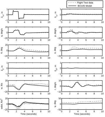
An example shown in Fig. 1.2 was recorded from a BO105 in-flight simulator operated by The German Aerospace Center (DLR) [4]. The impact of control system delays was displayed through a landing task, where a PIO manifested in the roll axis. This PIO was sustained at approximately 1 Hz for 4 seconds. Figure 1.3 displays the elements of the system which combine to cause the overall control delay. In this case, 43 % of the total delay is attributed to the ‘Actuators and Rotor’. As the complexity of rotorcraft control systems increase, it is possible that larger delays are experienced at each of the control system elements, causing larger overall time delays.
Figure 1.2: Trace of BO105 PIO. [4]
1.1.1 Classification of Aircraft/Rotorcraft Pilot Couplings
Figure 1.3: Control System of BO105 PIO. [4]
all possible PIO events. Prior to this structured system, there was no unified scheme for the analysis of Pilot-Induced Oscillations. Ashkenas specified the following;
“PIO’s are classed by the control axis involved, i.e., as longitudinal (pitch),
lateral (roll), directional (yaw), and coupled lateral-directional. The type
is defined by the nature of the physical phenomena (and, incidentally, the
kind of analysis) involved”
Three types of PIO were identified. These were;
I. Oscillations due to linear pilot-vehicle coupling
II. Limit cycles due to one or more nonlinear elements in series in the
primary control loop
III. Limit cycles due to one or more nonlinear elements in vehicle motion
feedback paths subsidiary to the primary control loop.
In 1995, McRuer [3] modified the system by replacing the class and type with Cat-egories (Category I, Category II, Category III). McRuer retained the meanings applied to the types defined by Ashkenas et.al in Ref. [2].
At the same time, the term Aircraft Pilot Coupling (APC) was proposed [7], as a means to avoid attributing any blame to the pilot during PIO events. The term also allowed for the inclusion of non-oscillitory pilot coupling events, which were not previously classified in Refs. [2, 3]. During this time, there was a stigma attached to the term PIO, resulting in a reluctance by pilots to report observed issues, as they did not wish to disclose that they had trouble commanding an aircraft [8].
occur over a larger frequency range in rotorcraft, but retain the same classifications as given in Ref. [4]. Due to increased vibrations and flexibility in rotorcraft, they are also believed to experience a wider range of pilot coupling events due to involuntary pilot control. Referred to as Aeroelastic RPCs, these include high frequency response due to the passive presence of the human pilot within the control loop. Oscillatory events are known as ‘Pilot Assisted Oscillations’ (PAO), and can occur through couplings with the airframe, the engine, or external influences (e.g. slung load, atmospheric conditions).
Figure 1.4: Tree showing division of APC events [9].
1.1.2 Problems Unmasking Aircraft/Rotorcraft Pilot Couplings
The primary reason for the continued presence of A/RPCs, is the unpredictability of interactions; almost every occurrence of undesirable pilot coupling is unique, caused by certain combinations of pilot, vehicle and mission requirements. Whilst A/RPC phenomena have been well researched in the past, there is a lack of a holistic approach to assist with the design, test, and evaluation process. As a result, and due to no specific requirements or guidelines, often no test or evaluation of A/RPC tendencies are conducted. Usually, any investigations are reactive, following problems experienced in-flight. This has been particularly true for rotorcraft investigations [10].
PIOs are the result of a coupling between three elements; the Pilot, Vehicle and a ‘Trigger’. All three are required for a PIO to occur, but the ‘requirements’ for each Pilot/Vehicle/Trigger are relatively unknown for every unique aircraft configuration.
Figure 1.6 shows a graphical representation of what happens to cause a PIO; the intersection of the Pilot/Vehicle/Trigger is the PIO region. However, elements of these regions are usually unknown and, for this reason, the size of the PIO region is also unknown. Elements including the operational condition of the vehicle may cause the unknown vehicle region to increase, changing the size of the PIO region. Furthermore, a particular pilot may interact with a larger range of vehicle dynamics, again causing the PIO region to increase. The result will be an increase in PIO susceptibility.
Figure 1.6: Diagram showing unknown elements of pilot, vehicle, and trigger that can lead to a PIO event.
the pilot believes should happen (the pilot’s mental model) and the actual response of the vehicle. In Ref. [11], the following was used to describe the distinction;
“One way of viewing the crucial distinction between oscillations resulting
from degraded handling and those that can result in a divergent PIO is to
note that in the former case the pilot drives the oscillation, whereas in a
“real” PIO ... the pilot is driven by the oscillation.”
Despite significant research in dynamics and control, it is still impossible to recre-ate a complete human brain and central nervous system as a mathematical model. Pilot modelling efforts have led to the development of models which can reproduce the actions of a pilot during closed-loop control of vehicles [12–14]. However, these can currently only represent elements of the pilot decision making process.
As each pilot operates differently, using their judgement of the situation and their individual strategy, it is difficult to predict how the vehicle will be controlled, partic-ularly in a PIO situation. The experience of the pilot plays a key role in the control activity; a trainee may over-control the aircraft causing an increase control gain or aggressiveness. They may also not recognise potentially catastrophic situations. All of these factors mean that, the response of the vehicle within a simulation cannot confirm that problems will not occur in flight.
The vehicle is perhaps the most well known of the three contributing factors to the occurrence of PIOs. This is mainly due to research efforts defining HQ criteria, and metrics that have been presented in the past 50 years. Although A/RPCs are not directly a HQ issue, there has been an effort to offer insight to A/RPCs through Handling Qualities analysis. Both fixed-wing (MIL-STD-1797-C [15]) and rotary-wing (ADS-33E-PRF [16]) have well established HQ guidelines. If the recommendations in these documents are followed, the vehicle should have good HQs, meaning that the vehicle should also be free from PIO tendencies. The linkage between PIOs and HQs comes through the systems implemented in the vehicle, namely the software and mechanical limits.
Figure 1.7: Diagram showing trigger groups.
The first are triggers caused through the difficulty of the task (through the lit-erature, these have been classified as Environmental Triggers [4]). Tasks which go beyond the capabilities of the vehicle and the pilot can act as a trigger. The closed loop control of the aircraft causes the pilot to work beyond the capabilities of the vehi-cle, leading to the pilot/vehicle mental-mismatch. These tasks could be in demanding stressful environments (e.g. war zones), in tasks where limits are of greatest impor-tance (e.g. nap-of-the-earth) or tasks with poor cueing environment leading to spatial disorientation (e.g. clouds, brownout). In 1995, McRuer [3, 17] related task perfor-mance (environmental) triggers to the situation where variable high pilot gain becomes necessary for desired control. Situations for this include precision landing in turbulent conditions, air-to-air tracking, flight refuelling, formation flying, landing on the deck of an aircraft carrier, manual terrain tracking, target tracking and landing in adverse weather conditions [17, 18]. High pilot gain however could be mistaken for poor pilot control strategy, and the A/RPC could be seen as a pilot triggered event. One example where high pilot gain could increase due to the environment is during collision avoid-ance. Low altitude flying over difficult terrain can cause excessive pilot control gain and, therefore, cause adverse A/RPC.
aircraft condition, or a sudden change in the system characteristics (such as a switch from command system or control sensitivity). A good example of this is the YF-22 case shown in Fig. 1.1. The pilot was flying a closed-loop approach, when a ‘go-around’ was initiated. When the afterburners were deployed, it caused an automatic change in pitch command gradients during the transition, causing unexpected and uncontrollable oscillations that resulted in collision with the runway [4]. This situation is very difficult to predict, as it is almost unique to every situation; i.e if the pilot had engaged the afterburners a second later, would the PIO have occurred?
The third type of trigger is the pilot. In some circumstances, it can be unexpected pilot control that can lead to the PIOs. A common occurrence is the over-control of the vehicle, leading to tight closed-loop flying where there is no task requirement. This can then replicate the type of experience found in high-gain, task triggered PIO events.
1.2
The ARISTOTEL Project
In 2001, the European Commission published “European Aeronautics: A Vision for 2020” [19], and later in 2011 published “Flightpath 2050: Europe’s Vision for Aviation” [20]. Within these reports, goals on safety, environment and European Air Transport efficiency were set. Regarding safety, the goal was set to achieve a five-fold reduction in the average accident rate of global operators and the drastic reduction of the impact of human error.
Due to the concern that A/RPC events may contribute to future aviation accidents, the ARISTOTEL project (Aircraft and Rotorcraft Pilot Couplings: Tools and Tech-niques for Alleviation and Detection), was initiated in 2010 [21, 22]. The three year project was funded through the European Commission (EC), under the 7th Framework Programme for Research.
The ARISTOTEL project detailed 6 key problems;
•Lack of understanding of what an A/RPC is,
•Lack of specific A/RPC pilot models,
•Lack of proper A/RPC vehicle models,
•No reliable A/RPC criteria,
•No proper simulator practices to unmask A/RPC,
The project was an international collaboration between 10 European institutions. Most of these parters were concerned primarily with rotorcraft specific problems. All research reported within this Thesis is funded through this project, and results from this work were reported in project dissemination activities.
The author was a member of the ARISTOTEL consortium, and involved in all project work packages where the University of Liverpool had involvement. This in-cluded both investigations of low and high frequency RPC. Primarily, the author con-tributed to aspects of Rigid Body RPCs, and to Simulation Testing for RPCs. Work conducted for the project included the creation and validation of helicopter models, preparation for simulated flight tests, data handling and post-processing, and prepa-ration of technical reports and joint conference papers. The work reported within this thesis helped the ARISTOTEL project reach some of the goals, particularly regarding simulator practices to unmask A/RPCs.
1.3
Thesis Objective
The objective of this research is to respond to the current threat of the ‘unknown’ PIO phenomena, with a view to answer research questions posed in the subsequent chapter.
•Improve experimental methods and analysis for use in Rotorcraft
Pi-lot Coupling investigations. This includes investigation of processes and
practices that should be undertaken in both a research and industrial
envi-ronment
•Development of novel tools for detection of Pilot-Induced Oscillations, to
provide feedback and protection for the pilot. There should be a way to
con-vey to the pilot the danger of PIO situations, in order to provide alleviation
and safety throughout the operation of the vehicle.
•Improve methods of pilot feedback during RPC investigations, to allow
the engineer to understand what the pilot experiences during completion of
closed-loop tasks.
•Provide novel robust methods for prediction of RPC/PIO tendencies, to
provide more understanding of pilot-vehicle susceptibility prior to real-time,
1.4
Thesis Structure
Chapter 1 presents an introduction to the work contained within the thesis. After introducing the background to the subject area, the goals of this current work are presented, along with the novelty of the work conducted.
Chapter 2 presents results of a literature survey of past research in Pilot-Induced Oscillations and Pilot Couplings. Results presented are aimed at the specific subject area of prediction and alleviation of Pilot-Induced Oscillations. Although work con-ducted in this research is using rotorcraft simulation, fixed wing analysis methods are presented to give sufficient understanding into work that has been completed before.
Chapter 3 details experimental set-up and modelling conducted in order to complete experimentation in following chapters. Simulation facilities are described, along with the modelling tools and techniques.
Chapter 4 presents the development of real-time algorithms for prediction of Pilot-Induced Oscillations. Theory, development and modelling of the real-time tools are discussed, along with methods of implementation. The chapter presents the results from a number of experimental test campaigns used to derive and validate boundaries for real-time PIO detection.
Chapter 5 presents the development of a new predictive tool to assess the potential for PIO prior to manned flight. This includes a number of methods and assessment metrics, derived from the real-time criteria developed. The use of the criteria is shown through a case study, involving a number of simple rotorcraft approximations.
Chapter 6 introduces a novel ratings scale for assessment of Adverse Pilot Couplings. The development and first use of the scale is shown through results obtained from an experimental test campaign. Within the chapter, the advantage the novel scale offers over pre-existing methods is shown through a series of examples.
Chapter 7 uses novel methods described in the preceding chapters to conduct a case study using data collected from real-time simulation. This demonstrates the use of previously developed tools to improve understanding of when and why PIO/RPCs occur during closed-loop flying tasks.
1.5
Originality and Novelty
The following are considered to demonstrate the originality and novelty contained within this thesis:
In Chapter 4, a novel real-time algorithm is presented, as a method to evaluate and identify PIOs in rotary-wing aircraft. The method has been specifically developed using data from rotorcraft closed-loop piloted simulations. The ability to use the algorithm without aircraft-specific tuning is not shown in any previous ‘detection method’.
In Chapter 5, the novel method presented in Chapter 4 is used as a prediction tool. This demonstrates the utility of the method for use in both the design stage and the evaluation stage. The utilisation in this way allows for standardised tools for both prediction and detection. This is not shown through current methods.
In Chapter 6, an original subjective rating scale for the assessment of RPCs is presented. This scale has been developed through cooperation with test pilots, during completion of closed-loop simulation trials. This new scale is shown to give more detailed information than results obtained using pre-existing scales.
Chapter 2
Literature Review
To establish an understanding of previous research regarding A/RPCs, a review of relevant existing studies was undertaken. This review was used to formulate research questions, determined through identification of the outstanding issues found.
2.1
Overview
Aircraft Pilot Coupling (APC) events, occurring in fixed wing aircraft, have been re-ported since 1947 but the first Rotorcraft Pilot Coupling (RPC) was not rere-ported until 1963 [2]. Figure 2.1 displays reported APC and RPC events for each decade from 1940 to 2010. These are combined from cases shown in Refs. [2–4, 10, 11, 21, 23–25]
As of 2010, there have been approximately 90 reports of APCs in fixed-wing air-craft. It is important to note that there is no requirement to report APCs that have not resulted in an accident. Therefore, these results represent only the most severe APCs encountered. It is likely that many more events have been disregarded as unimportant and were not reported at the time [4]. Reported events give a frequency of approxi-mately 1.5 incidents per year. Since 1963, approxiapproxi-mately 35 occurrences of RPC have been reported. The number of events is difficult to ascertain, as a number of rotorcraft were reported to experience ‘several occurrences’ of RPCs during their development and operation.
Figure 2.1: APC and RPC events per decade reported from 1947 to 2010.
increased again in the 1990s, suggesting that new problems emerged, which were not addressed by previously developed techniques. Unlike APCs, there has been a steady increase in RPCs since the 1960s and, in 2010, the number of reported events per decade was found to be approaching the reported number of APCs.
Although there appears to be no definitive trend concerning the nature of the APCs, the database of previous events shows periods characterised by certain trigger events. In the 1960s and 1970s, some of the first events concerning rotorcraft were caused by structural interaction between the main rotor and the fuselage. These events continued throughout the 1980’s and 1990’s, and were particularly prevalent in the V-22 tilt-rotor aircraft [10]. Here, interactions were found concerning the flexible airframe and the ro-tors. In the 1970s-1990s, a large number of events concerning sling-load transportations were found. Procedural mitigations were put in place to ensure safety during opera-tions. Finally, more recent events have been found to be attributed to control system forces, mode switching, system time delays, and lack of pilot experience.
Although there has been a change in the nature of events occurring in rotorcraft, it does not appear that this change has been driven by design guidelines or criteria. For example, many slung load interactions were mitigated against only through the requirement for the pilot to ‘drop the load’ if oscillations were experienced [10]. The results in Fig. 2.1 also show that there has been no reduction in the number of reported incidents. Therefore, further research is required in order to reduce or eliminate the threat of A/RPC.
re-search concerning them is extensive. The development of rotorcraft has generally lagged behind that of fixed-wing aircraft and, as a result, most of the past research has focused on fixed-wing APCs events [4]. Only limited research has been conducted to investigate RPCs (recent examples including [9, 26, 27]).
[image:33.612.160.484.249.473.2]The aim of the review is not to restrict the content of research to purely previous ro-tary research. Therefore, this review covers research both for fixed- and roro-tary-winged vehicles. It covers three main topics of A/RPCs: prediction methods, protection meth-ods, and Assessment/Evaluation Methods. An overview of previous A/RPC research topics is shown in Fig.2.2. These are discussed in the subsequent sections.
Figure 2.2: Overview of A/RPC research topics
2.2
Prediction of A/RPCs
For almost 50 years, the categorisation of PIOs has been used to develop prediction tools. As with protection methods, they have primarily been designed with fixed-wing aircraft in mind. The individual criteria are not however as readily applicable to rotor-craft as the protection methods, due to the differences in dynamics and flight regimes of the aircraft. Therefore, not all methods are discussed in detail here, but an overview of developments is presented.
•Validity: a criterion embodies properties and characteristics that define the
environ-ment of interest and are associated with parameter spaces covering the vast majority of
known cases.
•Selectivity: demands that the criterion differentiate sharply between “good” and “bad”
systems.
•Ready Applicability: requires that the criterion be easily and conveniently applied.
Initially, some of the first attempts to create criteria that followed these requirements resulted in a number of tools based upon identification of the properties of the closed-loop pilot-vehicle-system (PVS) [4]. These tools included Neal-Smith (1971, [28]), Smith-Geddes (1994, [29]), Aircraft-Bandwidth/Phase Delay (1994, [15]), Moscow Avi-ation Institute [4], and Dropback criteria (1994, [8]). The former two criteria are explic-itly based upon pilot models relating to compensatory control [4]. The latter consider the effective aircraft dynamics as an element of the open-loop system, which can be related to the closed-loop operations for which the pilot’s behaviour is synchronous [4]. All of these tools were initially developed to observe tendencies for linear, Category I PIO, as these were of most concern at the time. Furthermore, criteria were based upon the longitudinal axis, due to the database of events available. Criteria including Aircraft-Bandwidth/Phase Delay and Smith-Geddes were examined using lateral-axis experimental data. It was reported that the longitudinal criteria could be overly conser-vative for the lateral dynamics [4]. Some of the criteria developed for observation in the longitudinal axis are not directly applicable to the lateral axis, such as the Dropback criterion.
The validity of these criteria is shown through the observation of the PVS dynamics at the frequency range of interest for A/RPC.
The selectivity of the criteria has been achieved through the application of bound-aries, designed to encompass the results of pilot subjective opinion. McRuer et. al. [4] highlighted three points regarding the boundaries used for assessment:
•Boundaries were originally developed to distinguish between Handling Qualities Levels,
and only after development were they used to distinguish between PIO potential
•In principle, the boundaries could be different for different closed-loop task
scenar-ios (e.g., precision tracking and tight regulation, closed-loop manoeuvres, and
•The boundaries relating to rotorcraft are still a case in point.
The readily applicability of the criteria results from the use of simplified systems, which are considered appropriate for the observation of linear-type PIO.
With the prevalence of Category II events, novel criteria were required which include quasi-linear dynamics. A variety of new methods were developed including Time-domain Neal-Smith [30], the Open-Loop Onset Point (OLOP, 1994-97, [31, 32]), Power Spectral Density analysis (1997, [12, 33, 34]), Wavelett and Scalargram methods (2006, [11, 35]), and most recently Power Frequency methods (2011, [36]). In order to predict Category II PIO, the complexity of the criteria, and of the model, is greater than that required for Category I analysis. As a result, the criteria are not as readily applicable as the Cat. I criteria. Furthermore, the selectivity of the criteria can be difficult to ascertain.
As stated above, the boundaries for the application of criteria for rotorcraft are relatively unknown. This is due to the reason that all previous boundaries have been developed using fixed-wing databases. It is perhaps for this reason that only two of the criteria discussed above have been applied extensively to rotorcraft investigations.
Of the Category I prediction methods, only the Bandwidth Phase Delay (BPD) method has been extensively applied [37]. BPD was adopted within the fixed-wing specification MIL-STD-1797 [15] in 1997, to act as a method for determination of flying qualities of piloted aircraft.
Specifically, the BPD is based upon the premise of determining the maximum crossover frequency that a pure gain pilot can achieve without threatening the sta-bility [38]. If this frequency is higher than what is expected during closed-loop control, the vehicle is not likely to be prone to PIO. The determination of the BPD should give an indication of the ease of pilot control, and the tolerance of variations in the pilot dynamics close to the region of cross-over [4].
have been based upon fighter-type aircraft, but include results for some transport-type aircraft, such as the Boeing 777 and the MD-11 [4].
Due to its success in predicting fixed-wing PIO, and the ease of analysis, the method was chosen to determine the short-term response of rotary vehicles in Helicopter Aero-nautical Design Standard 33 in 1985 [40]. Refinements and modification led to the introduction of ADS-33E-PRF in 2000 [16]. Specifically, within ADS-33E-PRF, BPD is used as a method to determine the HQs of the vehicle. Although poor HQs are often a result of PIO tendencies, they are not exclusively caused in this way. Within ADS-33, boundaries for Handling Qualities Levels (HQLs) are presented. Although not specifi-cally stated in ADS-33E-PRF, the link between high phase delay, previous fixed-wing considerations, and the HQLs still exists to indicate PIO potential. Figure 2.3 displays a comparison of bandwidth and phase delay boundaries. The rotorcraft boundaries are shown for the roll axis, for Target Tracking and Acquisition (TTA) tasks. The fixed-wing boundary shows specific requirements for PIO detection.
Figure 2.3: Comparison between rotorcraft and fixed-wing bandwidth requirements (modified from Ref. [16]).
In 2008, Dieterich et. al [43] and Pavel et. al [44] presented results from GAR-TEUR Helicopter Action Group 12 (AG-12) where research was conducted specifically to determine the suitability of BPD susceptibility boundaries for prediction of PIO. Both the roll and pitch axes of a BO105 helicopter model were investigated, with PIO susceptibility engineered through the use of forward control path time delays. Results from real-time flight simulation (outlined in Ref. [26]) were used to determine whether fixed-wing BPD boundaries are directly applicable to rigid body rotorcraft activities. Theoretical PIO susceptibility was determined for 36 configurations. Overall, it was concluded that the results from the simulation tests were in agreement with predic-tions. However, high scatter was found between pilots, and it was recommended that further investigations should be undertaken and that further guidelines for experiments be determined [44].
In 2009, Blanken et.al. [45], used BPD to investigate effects of reduced stability margins on a H-60, H-53, and a Heavy Lift Large Civil Tilt-rotor concept (LCTR). The study aimed to observe the effects of phase margin on vehicle types which are larger than traditionally tested. Within the study, a number of PIOs were observed, confirmed through use of BPD results. From the study, it was concluded that all aircraft configurations evaluated with the lowest phase-margins (20-23 degrees) were unanimously rated as oscillatory, PIO prone, and objectionable [45].
In 2011, Mariano, Guglieri, and Ragazzi [27] completed further investigations to determine the applicability of the fixed-wing BPD boundary to rotorcraft. In the study, a number of longitudinal configurations were investigated, with the PIO susceptibility engineered through the use of changes to the actuator bandwidth. The analysis was undertaken at various airspeeds, from 0kts to 80kts. As in the study reported in Refs. [26, 43, 44], validation was completed using flight simulation. Findings showed that PIOs were triggered at much higher bandwidth’s than predicted by BPD (over double the values expected). It was concluded that the likely cause of the discrepancy was the sources of mismatch due to the simulator that were not present within the simulation model, including time delays. It was suggested that future analysis should be conducted using such a delay within the BPD model.
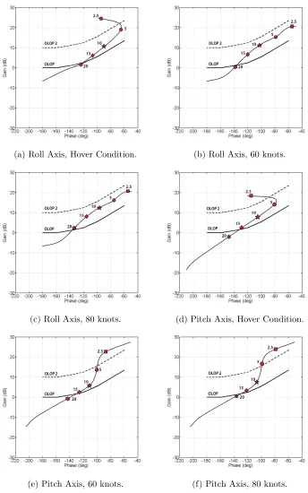
Only one Category II prediction method, Open-Loop Onset Point (OLOP), has been applied for analysis of rotory-wing vehicle susceptibility to PIO. Category II PIOs are usually the result of saturation limits, either hardware or software, within the flight control system. They may also be caused by repeatable system non-linearities.
although well established frequency domain PIO criteria could be extended to include the effects of rate limiting, this extension would be complicated. A new criterion was justified due to the observation that most of the catastrophic PIO incidents are a result of actuator rate limiting. Duda defined a new point on the Nichols chart: the point where a phase jump, associated with the closed-loop triggering of Rate-Limiting Elements (RLE) begins. The OLOP was defined as the frequency of the open-loop aircraft-pilot system at this closed-loop ‘phase jump’ frequency. This is shown in Fig.2.4. Duda defined boundaries, for the allowable position of the OLOP, through analyses of a number of experimental databases, including those from F-18 and YF-16 aircraft conducted in the Lateral High Order System simulator (LATHOS). The method was proposed as a tool for use in the early design stages of new flight control systems. However, the main uncertainty with the method was the reservation regarding pilot behaviour during the onset situation. The method uses a pure gain pilot model, which provides an estimation for the pilot control strategy. This is based upon the linear system, and does not account for the RLE within the system. The actual pilot behaviour during rate limited control is considered relatively unknown [31].
Figure 2.4: OLOP Example (taken from Ref. [46]).
rate limiting. In Ref. [47], Wilmes and Duda suggested a more conservative boundary for the use of OLOP. However, this has not been adopted in further studies to date.
In 2000, Duda et. al [48] presented further validation results from 342 pilot-in-the-loop simulation runs on fixed-wing fighter type aircraft (F-18, YF-16 databases). Five experienced test pilots completed evaluations in the roll axis. Overall, the use of OLOP for prediction of Category II PIOs was shown. The use of OLOP for limits in both the forward and feedback control loops was demonstrated, suggesting the latter to be a more significant problem. Validation was conducted through an analysis of the ‘change in PIO rating’ awarded for linear and nonlinear vehicles. Good correlation was found, and reasons were justified for those results that were not found to reflect the boundary. Reasons included high sensitivity to pilot gain, the use of intentional low gain from transport pilots, and PIO tendencies for the linear models (for the YF-16 results) [48]. It was concluded that despite results further justifying the use of OLOP, experience is required when interpreting results, and the criterion cannot be considered as a ‘cookbook’.
In 2008, Pavel et. al. [44] applied OLOP to rotorcraft models. The analysis was conducted for both low gain and medium gain pilot models, for configurations inves-tigated in a roll tracking task. The conclusion from the study was that the boundary for analysis of rotorcraft lies somewhere between the originally presented boundary (in Ref. [46]) and the more conservative OLOP boundary, presented in Ref. [47].
In 2008, Tischler et. al. [49] applied OLOP to a model of the XV-15 tilt-rotor, in the directional axis. The result was calculated for the aircraft FCS loop only, and did not include any pilot model, as used in previous references. This was to show stability in the open-loop system when the rate limiter is initially activated. Tischler et. al. found the method a good compromise in the short term, as they stated the use of a pilot model tends to severely (and unrealistically) limit predicted performance. Using the OLOP boundaries, the XV-15 was found to be marginally inside the ‘PIO unlikely’ region. Further analysis using OLOP was conducted showing the movement towards the ‘PIO region’ with increases in disturbance rejection bandwidths (DRB). The primary method for this analysis was to demonstrate how OLOP could be used within the rotorcraft design loop, and during optimisation. In the analysis, OLOP was found to be a limiting factor in the optimisation process. Without its use, the design could meet all Level 1 requirements.
the NASA Vertical Motion Simulator (VMS), nonlinear actuator rate limiting was fre-quently found to occur. On at least one occasion, rate limits caused divergence at the end of a completed test manoeuvre (which was only ended through stopping the sim-ulation). With the high system bandwidth, the actuators could not adequately handle pilot commands. Results from OLOP confirmed the PIO susceptibility. The criteria was used to observe the difference when the natural frequency of the command model was reduced. For the revised design, completed using results from OLOP, very little rate limiting was observed. It was commented that the use of OLOP saved significant time during investigations, and concluded that the tool is a legitimate method for rotor-craft analysis. However, it was stated that further flight data is required to determine a more precise rotorcraft boundary.
In 2011, Mariano, Guglieri, and Ragazzi [27] completed further investigations to determine suitability of OLOP boundaries for rotorcraft investigations. Overall, results from simulator experiments were in good agreement with those from OLOP predictions. However, the criterion was found to be very sensitive to stick deflection factor. When maximum stick travel was used, OLOP over predicted PIO tendencies. A sensitivity analysis recommended that a value ‘representative of pilot control in normal operations’ should be used.
2.3
Protection against A/RPCs
2.3.1 Suppression
PIO suppression filters were first used in the alleviation of PIOs experienced during landing of the ALT-5 Space Shuttle in 1977. They are usually intended as a short term measure when a full redevelopment of control systems cannot be completed [50]. In 1979, the Total In-Flight Simulator (TIFS) investigation examined two PIO suppression filters that were proposed for additions to the shuttle FCS [51]. In 1980, Smith and Edwards presented the design of the shuttle adaptive suppression filters [29]. They were designed to limit the rate limiting by attenuating pilot command path gain near the cross-over frequency. The nonlinear adaptive method was used to limit applied phase lags, as seen with linear compensation methods [29]. These filters were implemented in the shuttle FCS prior to its first flight. The filters attempt to estimate the frequency of the pilot’s input, and attenuate as a function of this frequency. Ref. [52] states that the drawback here is that the pilot input is attenuated whether is it required or not.
In 1980, a test programme was initiated to implement filters from the TIFS shuttle investigation in more conventional aircraft. The F-8 DFBW aircraft, originally used to investigate effects of time delays, was used to investigate two types of filters. Although the filters suppressed PIOs in the presence of added transport delay, they did not help with the configurations that exhibited first order lag [51].
In 1981, Bailey and Smith [53] presented results from an investigation into the use of suppression filters to mitigate against PIO. This was performed for a fighter aircraft (NT-33A), during a landing and approach task. Two types of adaptive filters were tested in the programme; both acting as a function of stick position. Briefly, weighted stick rate functions were considered. PIO filters were created through variation of the gain attenuation schedule, and no consideration for pilot input frequency was given. Both rate and position of the control stick were considered to feed to a gain attenua-tion schedule. Whilst the experiments clearly showed that the suppression filters could improve HQs, the recommendation was further follow-up programmes to evaluate dif-ferences in internal filter implementation, interaction between PIO filtering and short period dynamics, and the influence of actuator rate limiting.
conditions. The application of these filters can also lead to a delayed recovery, where a high performance aircraft flies like a large transport aircraft [54].
In 2007, Walden [10] reported a number of case studies from suppression of higher frequency RPCs (PAO phenomena) in naval rotorcraft. In the study, Walden showed that a common method used was to add specific notch filters once excited frequencies were identified through analytical and in-flight observation. Table 2.1 summarises some of the cases detailed. Although Walden’s study highlighted many problems solved through filtering methods or changes to design, it also showed that some problems have been solved through changes to procedures. Whilst these change are the most simple to implement, they do not account for how the coupling may materialise in future operations, where the role of the aircraft or additional operations are modified.
Although shown to adequately mitigate against A/RPCs tendencies which have been experienced many sources state that due to the requirements to modify pilot control inputs, they degrade general HQs. Ref. [55] states “Suppression filters ... attenuate (pilot) commands and add phase lag to the aircraft response, degrading general HQs, especially for high bandwidth tasks.” Furthermore, Ref. [56] states that a disadvantage of the systems is that they are ‘always active’. Whilst notch filters can perfectly remove oscillation tendencies at known frequencies, if the pilot faces a situation where they must for some reason tightly control the aircraft, the task is no longer possible. If for example pilot control is required for collision avoidance, it may not be possible to escape the situation.
2.3.2 Compensation
The SAAB JAS-39 Gripen was developed as an attack and reconnaissance aircraft to replace SAAB Viggens and Drakens [57]. During testing, two prototype aircraft catastrophically crashed, both caused by PIO triggered by actuator rate limiting. Both events, in 1989 and 1993 were filmed, and almost led to both the cancellation of the program and loss of life. Indecently, the same pilot, Lars R˚adestr¨om, was at the controls for both crashes. A detailed analysis of both accidents is contained within Ref. [58]. The events were a catalyst for increased research efforts regarding compensation. Whereas the ALT-5 shuttle had led to suppression filters, the SAAB crashes required a solution to deal with quasi-nonlinear elements of the system.
Table 2.1: Historical Events and Solutions in Naval Rotorcraft. [10]
Year Type Freq. Reason Solution
1967 CH-46D 3.2 Hz Shuffle Mode
Air Resonance created by the lightly damped main rotor regres-sive lag mode, causing out-of-phase de-patterning of the forward and aft rotors.
Changes to blade characteris-tics and 3.2 Hz notch filter
Early 1980s
CH-46E 3.5 Hz Shuffle Mode
Low speed, insufficient rotor lead-lag damping and pilot lateral cyclic stick coupling through the SAS.
Changes to roll axis viscous dampers, and procedural mit-igations
1981 SH-60B 3.0 Hz Ground Roll oscillation
Coupling between roll mode with the main rotor system’s regressive lag mode.
Procedural mitigations, to re-duce rotor flapping
1982 SH-60B 6.5 Hz Vertical bending mode
Caused during high speed autoro-tations and turns and dive recover-ies
Procedural mitigations, ability for pilots to disable longitudi-nal boost servo.
1981 CH-53E 3.4 Hz Vertical bending mode and 4.3 Hz Lateral bending mode
Interaction with modes through the AFCS, despite the presence of notch filters to attenuate pilot in-put. Materialised during trans-portation of external loads.
Reduction in roll axis FCS gains and the implementa-tion of procedural mitigaimplementa-tions through the removal of lateral control oscillations and load jettison
1989 V-22A 1.4 Hz Roll Mode Ground based, unstable and un-predicted lateral/roll mode oscilla-tion, involving coupling with the aircraft’s high focal roll mode. Ef-fect of aircraft lateral cyclic control grip behaviour.
Viscous dampers and filtering were not considered adequate solutions due to potential ad-verse effects on HQs. Added lateral balance weight on the cyclic.
1990 V-22A 3.2 Hz Wing Chord Bending Mode
Coupling with lateral control dur-ing divdur-ing flight. Initiated after the installation of a reduced stick damper whose purpose was to im-prove control feel.
Addition of 2.3 Hz asymmetric notch filter
1991 V-22A 3.8 Hz symmetric wing chord bend-ing
During sling-load operations, pi-lot coupling through longitudinal cyclic.
Addition of Notch Filters to al-leviate the coupling by atten-uation of the pilot control in-puts.
1991 V-22A 4.2 Hz symmetric wing chord bend-ing
Coupling with the pilot thrust control lever motion in forward flight. Inadvertently triggered through movement of both the thrust control lever and longitudi-nal cyclic
Notch filters at 4.2 Hz and 5.3 Hz installed, eliminating PAO.
1997 V-22B 1.4 Hz Roll Mode Ground based, re-emergence of mode previously experienced in V-22A, in part due to a reduction in the mass balance weight on the cyclic due to a reduction in FCS gain.
Modified stick gain shaping (reducing gain at 1.4 Hz) and procedural mitigations to relax the hand grip to terminate mo-tion.
2003 V-22B 2.3 Hz Asymmetric Drive System
During critical azimuth testing, at an airspeed of approx. 40 knots, divergent oscillations fol-lowed by sustained oscillations causing swashplate rate limiting. Coupling through lateral cyclic, treated previously with notch fil-ters.
channel. Situations are dangerous as it often appears that a lack of control gain must be compensated for through an increase in pilot control gain. However, this further sat-urates actuators, and causes the effects of unexpected dynamics to magnify. The term Anti-Windup (AW) filter refers to a system that attempts to avoid actuator saturation by causing a change in control system dynamics when approaching or reaching satu-ration. Usually these systems employ some combination of feed-back and feed-forward control to unload actuators whilst still allowing pilot control of the aircraft.
In 1980s, the Naval Air Systems Command (NAVAIR) developed phase compensa-tion filters to reduce effects of rate limiting. The time-domain filter was set to reverse the direction of the actuator when the actuator is on its rate limit and if the actuator is travelling in the opposite direction from its command. The filter was patented by the U.S. government. However, Ref. [59] states that problems were discovered regarding sensitivity to input noise, and a tendency to develop an offset bias over time. However, these problems could be overcome through additional complexity.
Rundqwist et.al. [60] developed a compensator, commonly termed the SAAB com-pensator, as a preventative filter in response to the second SAAB accident. In 1996, the system was presented within U.S. patent 5,528,119 [60]. This type of filter is referred to as a Feedback-with-Bypass (FWB) filter. The low frequency elements of the con-trol input are passed through a software rate limiter (SWRL) set to the actuator rate limit. During Rate Limiting, the input signal to the SWRL is larger than the output, creating a measurable difference. This difference is added to the pre-SWRL signal, after it passes through a low pass filter. The difference signal will have a different sign to the input, therefore reversing input phase. Therefore, phase lead is added to the system, which results in a rate-limited signal with significantly less phase distortion. A problem identified with the system was the possibility for high frequency disturbances, but favourable pilot comments during flight tests gave enough confidence to continue with production. In Ref. [47], Wilmes and Duda concluded that this is one of the most effective compensatory systems to suppress PIO due to rate limiting.
In the 1990s, much work was done regarding phase filters that compensated through the reversal of pilot input, through software rate limit (SWRL) compensation. This has been referred to as the “Differentiate-Limit-Integrate” (DLI) method. [61]. Using this method, amplitude attenuation is unavoidable. The input signal to an actuator is filtered by determining the derivative, limiting the rate, and then integrating. The output of the filter reverses in rate relative to the control input.
2 through the addition of the RLC, with few PIO tendencies. The RLC featured a bias removal feature, which was found to cause attenuated response to abrupt inputs, reduce predictability of the aircraft, and cause out-of-trim conditions. Furthermore, all of these undesirable effects were exacerbated by noise or high frequency content [62]. A recommendation was that the bias removal feature be redesigned to eliminate the sensitivity to noise. In 1997, Ohmit discovered that an automatic bias removal was unacceptable. Moreover, automatic bias removal during benign conditions led to commanded input, also deemed unacceptable [63].
In 1990s, the Deutsche Aerospace Aktiengesellschaft (DASA) compensation scheme was developed, simply a feed-forward filter which allows control signals to pass unat-tenuated if its rate is below the threshold of the rate limiter, and attenuates the input signal if it is higher. This is achieved by using a feed-forward SWRL, in series with both a lead and lag filter. The main drawback of this approach is considered to be the lack of feedback within the system [64]. Wilmes and Duda [47] concluded that the system did not seem quite as effective as the SAAB compensator.
In 1999, Chapa [63], as part of the HAVE FILTER program, presented a novel nonlinear filter, the rate limiter prefilter (RLPF), based upon the principle of reversing phase with the input. Chapa recognised that the big problem with previous DLI tech-niques was the removal of system bias, and the sensitivity to noise. Chapa implemented a system to remove bias quickly through the use of a reset integrator, and achieved noise filtering through off-line analysis. Chapa concluded that the addition of a SWRL only showed promise at protecting against instability, but could be set so low as to have a degrading effect upon aircraft HQs. Furthermore, the use of both RLPF and SWRL could also lead to degradation in HQs, but could allow a higher SWRL to be set whilst still avoiding PIO. Chapa however discovered that, even with the bias removal system, a large bias build-up sometimes occurred during aggressive manoeuvring, leading to either non-responsive or opposite pilot commands.
the low gain pilot than the SAAB scheme. However, with high gain pilot and large inputs, the SAAB method was found to produce better results. In the study, there was limited tuning of the H∞ controller, and no tuning of either SAAB or DASA systems. Therefore, it was not fully understood whether any of the filter systems were set to optimal response. In Ref. [65], it is claimed that theH∞ scheme has the ability to handle multi-variable systems, unlike SAAB and DASA systems which are SISO in nature. However, this study was not completed. Further results were presented within Ref. [66]. Since this work, a number of further studies have been completed by Postlethwaite, Turner, Sofrony, and Brieger, including work described in Ref. [67–70]. These have mainly focused on improving the rigour of processes to determine selection of AW system characteristics.
In 2002, Liebst, Chapa, and Leggett [71] demonstrated the use of the RLPF and a SWRL in both motion based simulation and flight test results. Flight tests were conducted in the NF-16D Variable Stability In-flight Simulator Test Aircraft (VISTA). The combination of the RLPF and SWRL filters were shown to prevent departure and/or PIO in the vast majority of cases that were susceptible before addition of the filters.
In 2004, Alcala et. al. [54] presented a method of phase compensation to mitigate against Category II type oscillations. Here, a nonlinear filter was proposed that com-pensates the phase of the control signal before it reaches the control surface. Alcala et. al. stated that the best method of compensation was feedback, but that current ex-isting methods required very careful choice of parameters for particular circumstances. Alcala’s phase compensator feeds back the output signal and obtains the error signal. The error signal feeds a phase-lead network, with the result summed with the original output and passed through a rate limiter block. The authors stated that the system was advantageous over previous methods as the compensator does not rely on the am-plitude of the signal, and the system can be easily tuned. However, the system is only capable of detecting and suppressing Category II type oscillations.
![Figure 1.1: Trace of YF22 PIO. [4]](https://thumb-us.123doks.com/thumbv2/123dok_us/8039618.220902/20.612.181.452.72.483/figure-trace-of-yf-pio.webp)


![Table 2.1: Historical Events and Solutions in Naval Rotorcraft. [10]](https://thumb-us.123doks.com/thumbv2/123dok_us/8039618.220902/43.612.118.476.144.688/table-historical-events-solutions-naval-rotorcraft.webp)

![Figure 2.10: GARTEUR AG-12 Rating Scale. [99]](https://thumb-us.123doks.com/thumbv2/123dok_us/8039618.220902/58.612.131.510.73.313/figure-garteur-ag-rating-scale.webp)