www.elsevier.com/locate/jmbbm
Available online at www.sciencedirect.com
Research Paper
Optimisation of composite bone plates for ulnar
transverse fractures
N.D. Chakladar
n, L.T. Harper, A.J. Parsons
Composites Research Group, Faculty of Engineering, University of Nottingham, NG7 2RD, United Kingdom
a r t i c l e i n f o
Article history:
Received 22 August 2015 Received in revised form 19 January 2016
Accepted 25 January 2016 Available online 4 February 2016
Keywords: Ulna Bone plates
Mechanical properties Composites
Finite element analysis
a b s t r a c t
Metallic bone plates are commonly used for arm bone fractures where conservative treatment (casts) cannot provide adequate support and compression at the fracture site. These plates, made of stainless steel or titanium alloys, tend to shield stress transfer at the fracture site and delay the bone healing rate. This study investigates the feasibility of adopting advanced composite materials to overcome stress shielding effects by optimising the geometry and mechanical properties of the plate to match more closely to the bone.
An ulnar transverse fracture is characterised and finite element techniques are employed to investigate the feasibility of a composite-plated fractured bone construct over a stainless steel equivalent. Numerical models of intact and fractured bones are analysed and the mechanical behaviour is found to agree with experimental data. The mechanical properties are tailored to produce an optimised composite plate, offering a 25% reduction in length and a 70% reduction in mass. The optimised design may help to reduce stress shielding and increase bone healing rates.
&2016 Elsevier Ltd. All rights reserved.
1.
Introduction
Diaphyseal fractures (transverse to bone shaft) of the ulna are sometimes treated with internalfixations such as bone plate/ screw systems to provide support to the fractured bone and to assist healing. These plates are designed to stabilise the fracture and to restrict further damage, by bringing the broken bone ends together and fixing them using neutral and compression screws. Thisfixation enhances the primary and secondary bone healing rates (Aro and Chao, 1993). In the last decade, there has been scientific development in surgical devices and techniques to improve patient comfort (in terms of post-surgical biomechanical movements), accelerate rate
of healing and introduce bio-adaptive implant designs (i.e. lessening damage to neighbouring bone tissues). Titanium (Ti) and stainless steel (SS) alloys are commonly adopted for orthopaedic trauma fixation devices, but stress shielding, reduced callus growth rate and increased risk of second surgery are of concern. In general, Young’s moduli of metallic alloys (105 GPa for Ti alloy; 280 GPa for SS alloy) are too high, restricting stress transfer across the fracture site, commonly called ‘stress shielding’. Since the callus formation rate is directly proportional to the compressive force between the fracture ends this shielding delays callus formation, which retards the bone healing rate (Bagheri et al., 2014; Ganesh et al., 2005). In addition, bone resorption (a process where
http://dx.doi.org/10.1016/j.jmbbm.2016.01.029 1751-6161/&2016 Elsevier Ltd. All rights reserved.
nCorresponding author.Tel.:þ44 1159513822.
E-mail address:ndaschakladar@gmail.com(N.D. Chakladar).
bone breaks down to release its minerals into the blood) sometimes takes place due to a reduction of mechanical stresses around the fracture site, which weakens the integrity of the bone and initiates bone re-fracture (Tonino et al., 1976). Bio-absorbable materials are gaining popularity as non-metallic substitutes, with a global market of $1.5B in 2014 and being the fastest growing segment of the internal fixation market at 8.4% CAGR (Orthopaedic Trauma Fixation Devices Market, 2014), but this technology is still relatively immature and limited by the availability of suitable materials. Resorb-able polymers, such as polylactic acid, polyglycolic acid and polycaprolactone, show substantial bioresorbability and are frequently used as one of the main constituents in the manufacture of biocompatible implants. However, the plate thickness is often increased to extend the biodegradation time, due to low initial mechanical strength and rapid loss of mechanical properties in the bio-environment, increasing the cost and quantity of polymer required.
Such effects can be counteracted by reinforcing the poly-mer, for example with carbon nanotubes (Sahithi et al., 2010), carbon fibres (Evans and Gregson, 1998), bioglass (Moritz et al., 2014;Rezwan et al., 2006), magnesium (Murugan and Ramakrishna, 2005), hydroxyapatite particles (Kasuga et al., 2000) or phosphate glasses (Liu et al., 2014a;2014b;Tancred et al., 2015) to form reinforced bio-active composites. Unlike metals, the mechanical properties of composite materials can be tailored to suit the specific design and application require-ments, in order to counteract the effects of stress shielding (Cifuentes et al., 2012; Wan et al., 2014). Apart from the tailorability of composite materials the choice of reinforce-ments is equally important–hip arthroplasties made of stiff carbonfibres reported failure due to inadequate bone/implant interfacial bond (Evans and Gregson, 1998). Hence careful selection of reinforcements is subject to bio-mechanical limitations. For example, theflexural modulus of a glassfibre reinforced composite (11.9 GPa) matches to that of a human cortical bone (12.5 GPa) (Lotz et al., 1991) which poses the composite as a suitable substitute of bone replacements.
All these biocompatible or bioabsorbable composite solu-tions require full mechanical characterisation under in-vivo and in-vitro conditions, but these are not alwaysfinancially viable and there are a number of ethical issues delaying further development and uptake of this technology. Numer-ical simulation is an efficient way to understand the bio-environmental impact and also understand the response according to a particular patient's geometry, ensuring tailor-made implants can be manufactured reliably. Finite element (FE) studies on torsional response of rabbit femur models, fixed with metal or fibre reinforced composite implants, observed a significant rise in the strain energy density peak and a pronounced effect of stress-shielding when the bone/ implant bond was considered. This means the compatibility of the bone/implant interface characterises the healing rate and bone remodelling (Zhao et al., 2009). Other comparative simulations have shown that stress shielding can be success-fully reduced when a composite plate is selected to repair a fractured tibia (Bagheri et al., 2014; Ganesh et al., 2005). However, these studies failed to capture the location offinal failure and predict the failure strengths of the composite-plated construct, as the results were sensitive to the contact
constraints used at the bone/screw, plate/screw and bone/ plate interfaces (Samiezadeh et al., 2015).
The work presented here aims to facilitate the replace-ment of traditional metal plates using a bioabsorbable glass fibre reinforced polymer composite. Since phosphate glass fibres are still developmental, E-glass textiles are used in this study as a representative commercial material with similar material properties. The size of the composite plate is optimized around the dimensions of an eight hole stainless steel plate (made by Depuy Synthes). A sensitivity study is conducted to select the optimum composite plate width/ thickness to match the stiffness of the composite-plated fracture construct to that of the intact bone. A complete ulnar transverse fracture (commonly referred to as a‘ night-stick fracture’) is assumed in the study, with a 0.5 mm fracture gap. The bending behaviour of Sawbones composite bone models is found to closely match the bending response of cadaveric bones (Cristofolini and Viceconti, 2000). As pointed out by (Zhao et al., 2009), the strength of implants or bone/implant system need to be matched with the local requirements of the skeleton along with its structural stiff-ness, this study investigates both the stiffness and strength and compares the values from models of intact and plated fractured bones to the experimental data using the composite bone surrogates. In addition, a sensitivity study is performed to identify suitable locations for applying six screws in an eight-hole SS plate, in order to match the construct stiffness to that of the intact bone.
2.
Experimental methods
Model ulnar bone specimens (4th generation composite Ulna, Sawbones Inc.) were procured for preparation and testing of fractured bones. The geometry and mechanical properties of these specimens are representative of the cadaveric ulna of a 180 cm tall, 38 year old male with a mass of 90 kg (Gardner et al., 2010). Specimens were moulded in a closed mould, with the inner trabecular part made from 17 pcf polyurethane foam and the cortex made from short-filled glass/epoxy. The specimen had an inner longitudinal hole to reflect the medullary canal of a real ulna.
Intact and fractured bone specimens were prepared for simply-supported three point bend tests in a universal testing machine (Instron, 5966 with 10 kN load cell and load mea-surement accuracy of70.5%). The test rig consisted of two fixed bottom rollers and a top roller attached to the cross-head. Two span lengths were used between the bottom rollers; 120 mm and 180 mm. This provided two different plate length to span ratios for the plated constructs, 0.87 and 0.57 respectively, which were expected to affect the stiffness of the construct and potentially the failure mode. The test velocity was 0.5 mm/min to simulate quasi-static bending of the bone (Cristofolini and Viceconti, 2000).Fig. 2shows the test set up at roller spans of 120 mm and 180 mm. Three specimens were prepared for each test and the mean and standard deviation were calculated for the stiffness (N/mm) and ultimateflexural load (N).
3.
Numerical methods
3.1. Extendedfinite element method
The Finite Element Method (FEM) requires a pre-defined cohesive damage zone to accurately predict crack initiation, evolution and propagation, to simulate material separation. This is relatively straight forward to position if the material contains initial voids/discontinuities or cracks, but is more challenging for a bulk material with homogenous properties (Park and Paulino, 2011). The Partition of Unity Finite Element
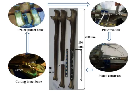
Method (PUFEM) (Babuska and Melenk, 1997; Melenk and Babuska, 1996) addressed some of the limitations of conven-tional FEM and provided a breakthrough in simulating cracks by introducing the discontinuous enrichment functions. PUFEM was further improved to allow for mesh-independent representation of the entire crack and was termed the Extended Finite Element Method (XFEM) (Moes et al., 1999). With the evolution of level set methods (Osher and Fedkiw, 2002; Osher and Sethian, 1988), the crack and crack-tip locations can be easily identified and coupled with XFEM to model crack propagation (Stolarska et al., 2001). The current study utilises the XFEM capability in Abaqus 6.14-1 to Fig. 1–Procedural steps of preparing a plated pre-cut bone.
[image:3.595.58.515.64.380.2] [image:3.595.313.532.409.570.2]identify, initiate and propagate cracks in intact bone or implanted fractured systems.
3.2. Finite element analysis
3.2.1. 3D model generation of intact and fractured bones An intact Ulna, supplied by Sawbones, was X-ray scanned using a pixel resolution of 45μm45μm at an image spacing of 45μm, yielding 6000 2D images for the 280 mm long specimen. These images werefiltered to separate the cortical and trabecular parts and then stitched in an image proces-sing package, Mimics with 3-matic (Materialise Inc.). Boolean operations were performed to assemble the cortex with the trabecular and generate a surface model of the bone geome-try. The faceted geometry of the ulna was then transformed into a solid model and analysed in Abaqus.
The CAD model of the intact bone was partitioned at the same location as the experimental specimens (84 mm from the narrowest end, see Fig. 1). The fracture surface was assumed to be planar and straight, but a 0.5 mm gap was introduced to account for some misalignment in the mated broken ends duringfixation. The Synthes stainless steel plate was modelled using available plate specifications (Synthes Fixation Techniques, 2002) and verified with the experimen-tal data. Stainless steel Ø3.5 mm cortical screws with but-tress threads were used to plate the broken bone. The screw thread profile was simplified to a uniform cylindrical geome-try to improve the efficiency of the FE analysis.
3.2.2. Material model
Bone is highly anisotropic (Weiner and Wagner, 1998) and the representative composite bones were manufactured to clo-sely match the initial linear elastic behaviour of cadaveric bones. The experimental stiffness was within 10% of values reported in the literature (Gardner et al., 2010). Hence, a linear elastic isotropic material model was adopted for the cortex and the trabeculae bone in the FE model. Damage properties of the bone were incorporated as a tension-compression based three dimensional Hoffman criterion (Eq. (1)) (Hoffman, 1967; Schellekens and de Borst, 1990). Subscripts 1, 2 and 3 indicate the longitudinal direction along the length of the bone (or the plate), the direction of loading in bending, and the transverse direction to bending respectively. s1, s2 ands3are the principal stresses along the respective direc-tions;Ci andTi are compressive and tensile strengths along thei-th direction respectively, wherei¼1 to 3.τijandSijare the shear stress and shear strength in theijplane (i,j¼1 to 3). If the left-term of Eq.(1)is greater than or equal to unity in a particular increment, damage initiates in that increment.
1 2 1 C1T1 1 C2T2þ 1 C3T3
s2s3 ð Þ2
þ12 C1 1T1þ
1 C2T2
1 C3T3
s3s1 ð Þ2
þ1 2 1 C1T1 1 C2T2þ 1 C3T3
s1s2 ð Þ2þ 1
T1þ 1 C1
s1
þ T1 2þ
1 C2
s2þ 1 T3þ
1 C3
s3þ τ12 S12
2
þ τ13 S13
2
þ τ23 S23
2
[image:4.595.309.546.66.185.2] [image:4.595.53.291.696.751.2]Z1:0 ð1Þ
Table 1lists the magnitude of failure stresses used in the Hoffman criterion user subroutine (Abaqus UDMGINI), from the literature (Aslan et al., 2003;Reilly and Burnstein, 1975).
The Hoffman failure criterion was programmed in Matlab, using Eq. (1) and the ‘isosurface’ command, in order to visualise the failure surface of the intact bone (Fig. 3). The stress planes (blue) denote the ultimate strength limits unidirectional compression and tension in all three direc-tions. Any state of stress lying on or above the Hoffman envelope (green) suggests material failure or initiation of damage. An effective working zone of the intact bone can be identified (shown in inset), with the fractured bone con-struct expected to exhibit a stress state in this working zone for a particular plate design.
The stainless steel plates and screws were modelled as elastic materials with isotropic hardening and the Maximum Principal Stress (MPS) criterion was used to determine failure, assuming linear damage evolution. The composite plates were modelled using elastic orthotropic properties and a similar Hoffman criterion for damage initiation/evolution. Table 2 shows the constitutive properties of the bone (Saw-bones biomechanical catalogue, 2015), the metallic and com-posite implants, along with otherfinite element parameters such as loading, contact conditions and solver type.
3.2.3. FE assembly
Bone has a very complex geometry and requires the meshing parameters and element type to be carefully selected. The shape factor was chosen to be greater than 0.0001 (default), the corner angles were between 51and 1701and the aspect ratio was less than 20 for all full integration tetrahedral elements (C3D4). Fig. 4 shows the meshed geometries for the intact bone, the fractured bone with screw holes, a screw, a SS plate and a composite plate. Further details of element type, element count and element size of all the parts is listed inTable 3.
The FE problem involved a multitude of contact interfaces – cortical/trabecular, bone/screw, plate/screw, bone/plate, bone/rollers. The interface between the cortical and trabecu-lar materials was merged by boolean operation, (retaining the boundary nodes) assuming that the magnitude of the force was shared between the outer trabecular and the inner cortex surface.
For the experimental samples, the plate gripped the bone through the screw holes, hence proper anchorage of the screws to the bone was essential in the numerical model, therefore, tie constraints were selected for the bone/screw interface. Additional bonding of the plate/screw or plate/bone was avoided, since the bone-screw interfaces were perfectly
Table 1–Failure properties of bone and composite screw/
plate for Hoffman criterion.
Failure strengths (MPa) C1 C2¼C3 T1 T2¼T3 S12¼S13¼S23
aligned and bonded. Also, the screw head preciselyfitted the countersink of the plate holes, restricting excess movement of plate. All contacts were modelled using surface-to-surface contact elements with penalty contact behaviour and an assumed friction coefficient of 0.25. The stiffer instance, in this case stainless steel, was the‘master’surface and bone was the‘slave’. Rigid bodies were used to model the rollers on the three-point bending of the bone. The bottom rollers were fixed in all directions and reference nodes were assigned to obtain the magnitude of reaction forces and deflection of the bone. A static, general solver was used to compute the stress– strain behaviour of the system, neglecting the inertia effects. Fig. 5illustrates the deformed configuration of a steel plated fractured bone construct. Crack initiation is identified by the Abaqus XFEM output variable PHILSM.
4.
Results and discussion
4.1. Experimental testing
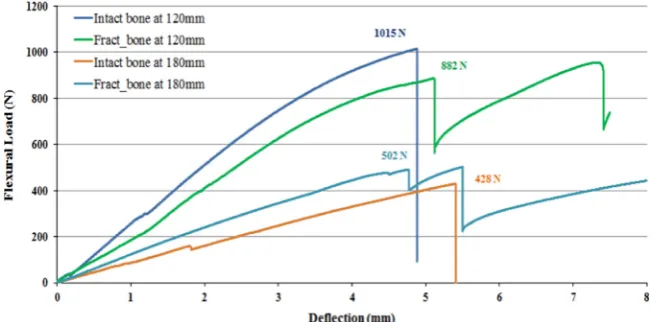
Load versus deflection curves are plotted in Fig. 6 for the intact bone and three steel plated fractured bone constructs at spans of 120 mm and 180 mm. Values for the ultimate flexural loads are indicated in thefigure. All plots indicate an initial linear elastic response, followed by some non-linearity and show signs of fracture at deflections between 4 mm and 5 mm, exhibiting a sudden drop in load.
[image:5.595.112.460.64.282.2]For the intact bone, the initial linear response up to a deflection of 3 mm denotes the stiffness of the cortical bone (in this case, 220 N/mm at 120 mm span and 80 N/mm at 180 mm span). The non-linear part of the curve beyond 3 mm Fig. 3–3D Hoffman Failure envelope and effective working zone (indicated by dashed red-arrow) of intact bone. (For interpretation of the references to color in thisfigure legend, the reader is referred to the web version of this article.)
Table 2–Constitutive properties of bone, implants andfinite element parameters.
Cortical (Isotropic) Trabecular (Crushable foam hardening model)(Kelly and McGarry, 2012;Tanwongwan and Carmai, 2011)
Loading and contact conditions Solver type
Elastic modulus (GPa)
E¼12
Elastic modulus (MPa)
E¼70
Displacement rate
v¼0.5 mm/min
Static, general
Poisson's ratio υ¼0.3
Poisson's ratio υ¼0.3
Friction coefficient μ¼0.25
Compression yield stress ratio¼0.7; Plastic Poisson's ratio¼0.2
316L Stainless steel(Portier et al., 2000) Composite (E-glass/epoxy)(based on a rule of mixtures)
Elastic modulus Isotropic hardening behaviour Yield stress (MPa), Plastic strain (Portier et al., 2000)
Elastic moduli Shear moduli
(GPa) (GPa) (GPa)
E¼280 E1¼15 G13¼7
E2,E3¼7 GPa G23,G12¼6
Poisson's ratio Poisson's ratios
υ¼0.33 υ23¼0.3
υ12,υ13¼0.25
[image:5.595.48.545.337.545.2]can be attributed to foam hardening of the inner trabecular bone (Kelly and McGarry, 2012; Tanwongwan and Carmai, 2011). The intact bone fails at aflexural load of 1015 N and deflection of 4.4 mm for the 120 mm span, whereas the ultimate flexural load drops to 428 N at a deflection of 5.4 mm for the 180 mm span. Failure occurred mid-way between the rollers, at the point of contact with the top roller in the case of intact bones (Fig. 7).
The fractured bone constructs failed at the screw holes at an average ultimate load of 882 N for the 120 mm span (initial stiffness equal to 182 N/mm) and 502 N at the 180 mm span (initial stiffness equal to 107 N/mm). These values were averaged over three specimens. The fractured bones did not completely part off at thefirst screw hole failure. The metallic plate work-hardened, further increasing the reaction forces, causing a series of bone failures at other vulnerable screw holes. This was observed as a saw-tooth effect on the load/ deflection curve following thefirst failure. The screw holes were prone to failure, as the bone/screw interfacial shear
strength was lower than the flexural strength of the intact bone. Fracture sites of intact and plated bone constructs are illustrated inFig. 7for the bending load case. The intact bones failed at the point of contact with the top roller for both spans. Plated bone constructs failed at the screw hole closest to the point of contact with the top roller, followed by additional screw hole failures. Thefirst screw hole failure is circled by a solid line inFig. 7and the subsequent failure is circled by a dashed line.
4.2. Model validation
[image:6.595.73.525.61.339.2]Thefinite element models of intact and steel plated fractured bones were validated using experimental data. For simplicity, the numerical models were validated up to the first screw hole failure of the construct.Fig. 8compares the simulation for the intact bone (dashed line) with the experimental data (solid line) at the 180 mm roller span. There is a blip in the experimental data at 2 mm which occurred due to the specimen slipping/rotating about the rollers during bending. The predicted stiffness of intact bone was 90 N/mm from the model, which was within the range of the experimental values (80710 N/mm). The predicted ultimate flexural load was 6% lower than the experimental failure load. The good agreement between the intact bone simulation and the experimental data provided confidence in the modelling approach for carrying out further numerical studies. The discrepancy between the numerical results and the experi-mental data can be attributed to the simplified modelling of the cortical/trabecular bone interface in the FE analysis. Fig. 4–FE meshed (a) intact bone, (b, c) fractured bone with screw holes and zoomed view, (d) simplified screw geometry, (e) Synthes SS 8-hole plate, (f) 6-hole compositeflat plate.
Table 3–Mesh characteristics of bone, screw, and plates.
Model name Element type Element size (mm)
Element count
Intact or fractured bone
C3D4 1.50 3.0105
Screw C3D4 1.95 1.6103
Synthes SS plate C3D4 1.95 4.3104 Flat composite
plate
[image:6.595.52.290.404.499.2]4.3. Size optimisation of composite bone plates
The cross-section of a 78 mm long compositeflat plate was optimised with the aid of FE simulations. The objective was to determine suitable plate width/thickness combinations to provide a similar construct bending stiffness to the intact bone. Widths ranging from 9 mm to 12 mm (in 1 mm incre-ments) and thicknesses from 3.35 mm to 5 mm (in 0.5 mm increments) were considered, according to existing specifi ca-tions of surgical plates (Synthes Fixation Techniques, 2002).
Bending simulations of the fractured bone constructs, plated with the composite plates, were then compared with experimental stiffness values for the intact bone (Fig. 9). Increasing the width of the composite plate by 33% (from 9 mm to 12 mm) for all plate thicknesses, increased the stiffness by 5%. However, when the plate thickness increased by a factor of 1.5 (from 3.35 mm to 5 mm), the construct stiffness increased by 33% for all widths. Comparing the stiffness values of the constructs with the intact bone indicates that a number of possible solutions are available offering a suitable stiffness, with acceptable widths ranging from 9 mm to 12 mm and thicknesses ranging from 4 mm to
5 mm (shown by pink arrows inFig. 9). The 10 mm4.5 mm geometry (indicated by a purple arrow inFig. 9) was chosen to be manufactured by selecting the median value for each variable.
Composite plates were manufactured from woven E-glass (600 gsm, 01/901 plain weave, supplied by EasyComposites) Fig. 6–Flexural response of intact and steel plated fractured bone constructs.
Fig. 5–XFEM crack contour in a loaded steel-plated fractured bone construct.
Fig. 7–Failure sites for intact and fractured bone constructs. j o u r n a l o f t h e m e c h a n i c a l b e h a v i o r o f b i o m e d i c a l m a t e r i a l s 5 7 ( 2 0 1 6 ) 3 3 4 – 3 4 6
[image:7.595.127.460.68.255.2] [image:7.595.132.459.297.458.2] [image:7.595.314.532.493.650.2]and epoxy resin (Prime 20 LV: Prime 20 Slow Hardener equal to 100:26, supplied by Gurit). Whilst the longer-term goal is to manufacture a biocompatible phosphate glass/PLA plate, the phosphate glass is currently unavailable in woven form. However, the stiffness of E-glass and phosphate glassfibres are similar, therefore this feasibility study will provide a good understanding of the stiffness requirements for the biocom-patible materials.
A sensitivity study indicated that 11 plies of 600 gsm woven E-glass would result in a thickness of 4.5 mm (sub-sequent burn-off tests indicated a fibre volume fraction of 54%). The plates were then machined to the required screw holes (Fig. 10(a)). A three-point bend test of the manufactured plate indicated failure at a screw hole, at an ultimate load of 514 N and a final deflection of 5.2 mm. The initial stiffness was 87 N/mm (Fig. 10(b)). Additional plots of construct
stiffness are included in Fig. 9 for the stainless steel and composite plates. The experimental result for the stiffness of the construct using the selected composite plate geometry (yellow square marker inFig. 9) is within8% of the stiffness of the intact bone. This is a big improvement compared to the stiffness of the metal plate/bone construct, which is 37% higher than the stiffness of the intact bone.
4.4. Stiffness and strength comparison of metal and composite plated fractured bones
Figs. 11and12present a comparison of stiffness (N/mm) and ultimateflexural loads (N) for the intact bones and fractured bone constructs respectively. Experimental and numerical results are presented for an intact bone, a steel plate/steel screw bone construct, a composite plate/steel screw bone Fig. 8–Experimental validation of intact bone model at 180 mm roller span.
[image:8.595.138.463.66.246.2] [image:8.595.138.463.284.523.2]construct and a composite plate/composite screw bone con-struct. Bend tests were performed at two spans–one at the free length of the intact bone (180 mm) and another across the assumed fracture site, taking into effect the metal plate (120 mm).
The experimental stiffness of intact bone (deep blue) decreases from 220 N/mm (120 mm span) to 80 N/mm (180 mm span) due to the variation in cortical and trabecular bone tapered geometries along the length (Fig. 11). A similar drop in stiffness is observed for the stainless steel plated construct (deep green) from 182 N/mm to 107 N/mm (40% reduction from 120 mm to 180 mm span) due to the ratio of the plate length over the span (0.57 at 180 mm span and 0.87 at 120 mm span). In general, the lower the ratio of plate length to span length, the lower the overall stiffness.
The numerical models were in good agreement with the experimental data for both spans, with the predicted stiffness values falling within 8% of the experimental values. The experimental stiffness of the composite plate/steel screw bone construct was 35% lower than the experimental data for the intact bone at the 120 mm span (because of the lower ratio of composite plate length to span, in comparison to the steel plate) and 10% lower for the 180 mm span. The simula-tion data was much closer to the intact bone benchmark, just 8% lower for the 120 mm span and 4% lower for the 180 mm span.
[image:9.595.135.465.62.332.2] [image:9.595.135.458.365.530.2]A fully composite plating system is anticipated for the future, with both screws and plates manufactured from composites. An FE model of a bone construct made using a composite plate and composite screws was developed to understand the magnitudes of the construct stiffness and Fig. 10–(a) Specifications, and (b) Bend test results of the composite plate.
Fig. 11–Stiffness comparison of intact and plated fractured bone constructs.
strength (shown in light orange inFig. 11and Fig. 12). This predicted a stiffness of 190 N/mm at 120 mm span and 73 N/ mm at 180 mm span, 14% lower and 9% lower than that of the intact bone, which was comparable to the construct that used steel screws
Fig. 12 compares the strength for all the models under consideration, in terms of ultimateflexural load (N) obtained from a three-point simply supported bending load. The fail-ure load of intact bone (shown in dark blue) was found to decrease from 1015 N (at 120 mm span) to 466 N (at 180 mm span). A drop in failure load was also registered in the case of the steel plated construct (shown in dark green) from 863 N to 502 N (i.e. 42% reduction in strength for an increased roller span from 120 mm to 180 mm). The numerical models showed good agreement at both spans, falling within 3% of the experimental data. The bone failed at the screw holes for all plated bone constructs, due to shear. For the composite plate/steel screw system, the bone failed at an ultimate flexural load of 841 N at 120 mm span and 487 N at 180 mm
span (shown in dark pink). This is encouraging as the composite plate did not fail catastrophically during the test, suggesting that the material properties and geometry of the composite plate are suitable for this application. The compo-site plate/compocompo-site screw construct (shown in light orange inFig. 12) failed at the screw hole in the bone at an ultimate load of 730 N for the 120 mm span, and 371 N for the 180 mm span. This indicates that a fully composite implant system could be used for an ulnar transverse fracture, as the plated system would offer suitable stiffness and strength.
[image:10.595.140.461.482.734.2]Fig. 13 compares the site of failure in the bone for the experimental specimen with the site in the simulation. The left image is for the metal plated construct and the right image is for the composite plated bone construct. Failures occurred in both the specimens at the screw holes which were close to the point of contact of the top roller. The screw hole in the bone introduces a stress concentration, which reduces the ultimate failure load of the bone, as the holes fail in shear. A similar failure location was observed in the FE
Fig. 12–Failure load comparison of intact and plated fractured bone constructs.
model when plotting the PHILSM contour of the crack in the fractured bone. The bone completely sheared off at the screw hole for the composite plating system during the experiment. The Abaqus XFEM plot supports this observation, however due to numerical instabilities at the crack front, the bone did not completely part-off. Fig. 13 confirms that the fracture sites have been reliably captured by the XFEM model.
4.5. Effects of screw positions on construct stiffness/ strength–an FE sensitivity study
Simulations were performed to model the bending behaviour of a stainless steel plated construct at a 180 mm roller span with different screw arrangements, in order to understand
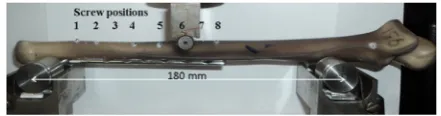
how the stiffness and strength of the construct are affected by the screw positions and whether the outcomes can have clinical implications.Fig. 14indicates the screw positions (S1 to S8) for the existing metal plated bone construct, in order from the narrowest end to the widest end of the bone. Fifteen possible combinations or patterns of six screw positions were analysed for an 8-hole steel plate (82C62¼15; where two
[image:11.595.56.277.237.295.2]screw positions werefixed in the middle across the fracture site for all combinations and omitted from the combinatorial selection). In addition, another combination (ALL inFig. 15(a)) was analysed, consisting of all eight screws in place.Fig. 15 (b) compares the stiffness and strength of all the screw combinations as predicted by the numerical model, with the experimental stiffness and strength of the intact bone. The initial failure site is indicated below each bar, where S8 indicates failure at screw hole 8 for example. The objective was to match the stiffness of the plated constructs to the stiffness of the intact bone (80 N/mm), whilst maintaining a similar ultimateflexural strength (466 N).
Fig. 15(b) indicates that symmetric combinations of screw positions (axis of symmetry about the fracture site) behaved
[image:11.595.131.463.330.721.2]Fig. 15–(a) Screw-combinations in an eight hole steel plate, and (b) their predicted stiffness/failure load with screw hole failure sites.
Fig. 14–Screw positions in a traditional plating system.
differently to non-symmetric combinations, due to the irre-gular geometry and stiffness along the length of the bone. Pattern I is based on existing fixation guidelines, which produced a stiffness of 107 N/mm and failed at a load of 502 N. Pattern VIII was equivalent to Pattern I but reversed on the bone, which resulted in a stiffness value that was 37% higher than for Pattern I because two screws were placed at the wider end of the bone (Pattern VIII inFig. 15(a)). However, Pattern VIII subsequently failed at a lowerflexural load (364N) at screw hole 7. This demonstrates that both the stiffness and strength generated by each screw pattern is dependent on the position of the screws across the fracture site, particularly whether they are concentrated on the narrower side or the wider side of the bone. This can be observed from the results of Patterns II, III, VII, VIII, XIII, XV and ALL, which all indicated higher stiffness values than Pattern I (about 50% higher than the experimental stiffness).Relatively low stiffness values were registered for patterns IV, V, VI, IX, X, XI, XII and XIV, which were within720% of the experimental result.
It was noted that the screw pattern that generated the highest stiffness did not always have the highest failure strength, due to the mismatch between the geometrical non-uniformity along the bone length and the screw pat-terns. A particular pattern (IX) outperformed the existing system (Pattern I) with a predicted stiffness of 97 N/mm and failure load of 489 N, standing out as an excellent alternative to the current screwing pattern. A change in failure site was observed for Pattern IX (screw position 7) compared to Pattern I (position 6).
The results from this study demonstrate a wide variation in construct stiffness, ranging from 97 to 166 N/mm, approxi-mately double the stiffness of the intact bone. Similarly, a range of ultimate flexural loads from 315 to 489 N was observed, in comparison to the flexural load of 466 N for intact bone. There is therefore a possibility of tailoring the stiffness of a plated bone construct without changing the plate material or location of the plate. Clinically, this widens the choice for arranging the screws based on the nature of the fracture, its position on the bone and the patient's bone properties.
5.
Conclusions
The design for afibre reinforced composite plate has been presented, which offers potential improvements over existing metallic plates for arm bone fractures. The wide range of material options and manufacturing routes offer different possibilities for achieving the desired stiffness for a bio-absorbable fibre reinforced implant. Composite plates can be tailored to specific stiffness values, reducing the occur-rence of stress shielding and offering a weight reduction of 70% in comparison to metallic plates.
In this study, a composite plated construct was demon-strated to have a similar stiffness and strength to intact bone. Predicted failure sequences and fracture sites from the FE model agreed well with the experimental data. Estimated stiffness and strength values of constructs were generally within 10% of experimental values. This error can be attrib-uted to simplified screw geometry and contact behaviour at
the screw/bone interface. When bending a metal plated construct at a span equivalent to the free length of the bone, the construct stiffness was 33% higher than that of the intact bone, whereas the stiffness of a composite plated construct was within 10% of intact bone. This successfully fulfils the aim of this study and offers composite materials as a potential and substitute for metal implants.
A sensitivity study investigating the influence of screw position highlighted that an alternative arrangement to the recommended fixation guidelines can be used, offering a closer match to the intact bone stiffness. The construct stiffness was 107 N/mm when plated according to the AO guidelines, whereas the alternative arrangement had a stiff-ness of 97 N/mm. This was closer to the intact bone stiffstiff-ness of 80 N/mm, whilst maintaining a similar failure load (489 N for the construct compared to 466 N for the intact bone).
Acknowledgements
The authors highly appreciate the funding support through an EPSRC-IAA grant EP/K503800/1. They also acknowledge Richard Dolby of Synthes Inc, for the use of the surgical tool kit and steel plates/screws; Prof Donal McNally and Dr Alan Parish, of the Bioengineering group, University of Nottingham for access to the 3D image processing facilities; and Dr Craig Sturrock for use of the X-ray facilities, Hounsfield building, University of Nottingham.
r e f e r e n c e s
AO Foundation, 2005. AO Surgery Reference.
Aro, H.T., Chao, E.Y.S., 1993. Bone-healing patterns affected by loading, fracture fragment stability, fracture type, and fracture site compression. Clin. Orthop. Relat. Res. 293, 8–17.
Aslan, Z., Karakuzu, R., Okutan, B., 2003. The response of laminated composite plates under low-velocity impact load-ing. Compos. Struct. 59, 119–127.
Babuska, I., Melenk, J.M., 1997. The partition of unity method. Int. J. Numer. Methods Eng. 40, 727–758.
Bagheri, Z.S., Sawi, I.E., Bougherara, H., Zdero, R., 2014. Biome-chanical fatigue analysis of an advanced new carbon fibre/ flax/epoxy plate for bone fracture repair using conventional fatigue tests and thermography. J. Mech. Behav. Biomed. Mater. 35, 27–38.
Cifuentes, S.C., Frutos, E., Gonzalez-Carrasco, J.L., Munoz, M., Multigner, M., Chao, J., Benavente, R., Lieblich, M., 2012. Novel PLLA/magnesium composite for orthopedic applications: A proof of concept. Mater. Lett 74, 239–242.
Cristofolini, L., Viceconti, M., 2000. Mechanical validation of whole bone composite tibia models. J. Biomech. 33, 279–288.
Evans, S.L., Gregson, P.J., 1998. Composite technology in load-bearing orthopaedic implants. Biomaterials 19, 1329–1342.
Ganesh, V.K., Ramakrishna, K., Ghista, D.N., 2005. Biomechanics of bone-fracture fixation by stiffness-graded plates in com-parison with stainless-steel plates. Biomed. Eng. Online 4, 1–15.
Gardner, M.P., Chong, A.C.M., Pollock, A.G., Wooley, P.H., 2010. Mechanical evaluation of large-size fourth generation com-poite femur and tibia models. Ann. Biomed. Eng. 38, 613–620.
Kasuga, T., Ota, Y., Nogumi, M., Abe, Y., 2000. Preparation and mechanical properties of polylactic acid composites contain-ing hydroxyapatite fibres. Biomaterials 22, 19–23.
Kelly, N., McGarry, P., 2012. Experimental and numerical char-acterisation of the elasto-plastic properties of bovine trabe-cular bone and a trabetrabe-cular bone analogue. J. Mech. Behav. Biomed. Mater. 9, 184–197.
Liu, X., Grant, D.M., Palmer, G., Parsons, A.J., Rudd, C.D., Ahmed, I., 2014a. Magnesium coated phosphate glass fibers for uni-directional reinforcement of polycaprolactone composites. J. Biomed. Mater. Res. B: Appl. Biomater. 8, 1–9.
Liu, X., Hasan, M.S., Grant, D.M., Harper, L.T., Parsons, A.J., Palmer, G., Rudd, C.D., Ahmed, I., 2014b. Mechanical, degra-dation and cytocompatibility properties of magnesium coated phosphate glass fibre reinforced polycaprolactone compo-sites. J. Biomater. Appl. 29, 675–687.
Lotz, J.C., Gerhart, T.N., Hayes, W.C., 1991. Mechanical properties of metaphyseal bone in the proximal femur. J. Biomech. 24, 317–329.
Melenk, J.M., Babuska, I., 1996. The partition of unity finite element method: Basic theory and applications. Comput. Methods Appl. Mech. Eng. 139, 289–314.
Moes, N., Dolbow, J., Belytschko, T., 1999. A finite element method for crack growth without remeshing. Int. J. Numer. Methods Eng. 46, 131–150.
Moritz, N., Standberg, N., Zhao, D.S., Mattila, R., Parachhini, L., Vallittu, P.K., Aro, H.T., 2014. Mechanical properties and in vivo performance of load-bearing fiber-reinforced composite intramedullary nails with improved torsional strength. J. Mech. Behav. Biomed. Mater. 40, 127–139.
Murugan, R., Ramakrishna, S., 2005. Development of nanocom-posites for bone grafting. Compos. Sci. Technol. 65, 2385–2406.
Osher, S., Fedkiw, R.P., 2002. Level Set Methods and Dynamic Implicit Surfaces. Springer-Verlag, Berlin.
Osher, S., Sethian, J.A., 1988. Fronts propagating with curvature-dependent speed: algorithms based on Hamilton-Jacobi for-mulations. J. Comput. Phys. 79, 12–49.
Park, K., Paulino, G.H., 2011. Cohesive zone models: a critical review of traction-separation relationships across fracture surfaces. Appl. Mech. Rev. 64, 1–20.
Portier, L., Calloch, S., Marquis, D., Geyer, P., 2000. Ratcheting under tension-torsion loadings: Experiments and modelling. Int. J. Plasticity 16, 303–335.
Reilly, D.T., Burnstein, A.H., 1975. The elastic and ultimate properties of compact bone tissue. J. Biomech., 393–405.
Rezwan, K., Chen, Q.Z., Blaker, J.J., Boccaccini, A.R., 2006. Biode-gradable and bioactive porous polymer/inorganic composite scaffolds for bone tissue engineering. Biomaterials 27, 3413–3431.
Sahithi, K., Swetha, M., Ramasamy, K., Srinivasan, N., Selvamur-ugan, N., 2010. Polymeric composites containing carbon nanotubes for bone tissue engineering. Int. J. Biol. Macromol. 46, 281–283.
Samiezadeh, S., Avval, P.T., Fawaz, Z., Bougherara, H., 2015. On optimization of a composite bone plate using the selective stress shielding approach. J. Mech. Behav. Biomed. Mater. 43, 138–153.
Schellekens, J.C.J., de Borst, R., 1990. The use of the Hoffman yield criterion in finite element analysis of anistropic composites. Comput. Struct. 37, 1087–1096.
Stolarska, M., Chopp, D.L., Moes, N., Belytschko, T., 2001. Model-ling crack growth by level sets in the extended finite element method. Int. J. Numer. Methods Eng. 51, 943–960.
Synthes Fixation Techniques, 2002. Locking Compression Plate System.
Tancred, D.C., McCormack, B.A.O., Carr, A.J., 2015. A quantitative study of the sintering and mechanical properties of hydro-xyapatitte/phosphate glass composites. Biomaterials 19, 1735–1743.
Tanwongwan, W., Carmai, J., 2011. Finite element modelling of titanium foam behaviour for dental application. In: Proceed-ings of the world congress on Engineering, London, UK.
Tonino, A.J., Davidson, C.L., Klopper, P.J., Linclau, L.A., 1976. Protection from stress in bone and its effects. J. Bone Joint Surg. Br. 58-B, 107–113.
Wan, P., Yuan, C., Tan, L., Li, Q., Yang, K., 2014. Fabrication and evaluation of bioresorbable PLLA/magnesium and PLLA/mag-nesium fluoride hybrid composites for orthopedic implants. Compos. Sci. Technol 98, 36–43.
Weiner, S., Wagner, H.D., 1998. The material bone: structure-mechanical function relations. Annu. Rev. Mater. Sci. 28, 271–298.
Zhao, D.S., Moritz, N., Laurila, P., Mattila, R., Lassila, L.V.J., Strandberg, N., Mantyla, T., Vallittu, P.K., Aro, H.T., 2009. Development of a multi-component fiber-reinforced compo-site implant for load-sharing conditions. Med. Eng. Phys. 31, 461–469.