THE SOLID WOOD FILLED TUBE UNDER AXIAL LOADING
TEO KAH CHUN
THE SOLID WOOD FILLED TUBE UNDER AXIAL LOADING
TEO KAH CHUN
This report is submitted
in fulfillment of the requirement for the degree of Bachelor of Mechanical Engineering (Structure and Materials)
Faculty of Mechanical Engineering
i
DECLARATION
I declare that this project report entitled “The Solid Wood Filled Tube Under Axial Loading”
is the result of my own work except as cited in the references
Signature : ...
APPROVAL
I hereby declare that I have read this project report and in my opinion this report is sufficient
in terms of scope and quality for the award of the degree of Bachelor of Mechanical Engineering (Structure & Materials).
Signature : ... Supervisor’s Name : ...
iii
DEDICATION
ABSTRACT
Efficient energy absorbers are widely made from thin-walled structures such as aluminium because of the good energy absorption capacity. In this paper, the behavior of hollow tubes and wood-filled tubes that subjected to axial loading in quasi-static test is studied. Agarwood which known as “Gaharu” would be the wood that been used in this study. To this aim, quasi-static axial loading test have been performed on square and circular aluminium tube. Experimental work showed the effect of solid wood for the energy absorption capacity of tubes. The mode of deformation for the circular tube and square tube is investigated. Results from the quasi-static test are presented on tubes of various length which consisted of 50mm, 100mm, 150mm and 200mm. Theoretical models of axial collapse modes for circular tube and square tube has been developed and established a comparison between theoretical results and experimental results. The results obtained for the mean load and plastic wavelength agreed reasonably with the experimental observations. Satisfactory agreement were generally achieved between theoretical value and experimental value of mean load and plastic wavelength. In this paper, it also highlighted the comparison of square tube and circular tube in terms of energy absorption and specific energy absorption. The energy absorption in wood-filled tube is shown to be higher than the hollow tube whereas the specific energy absorption in hollow tube is shown to be higher than wood-filled tube. Some observations are made on the influence of geometrical imperfection and the methods to reduce the deviation of theoretical value and experimental value.
v
ABSTRAK
ACKNOWLEDGEMENTS
I would like to acknowledge with much appreciation the crucial role of Prof. Dr Md Radzai bin Said, who gave permission for me to complete my final year project under his supervision. He is willing to teach patiently and guide me well in these two semesters of my final year project. He gives a lot of advices and encouragement to lead me to a correct way to complete my project. Next, a special thanks goes to the laboratory technician, Encik Faizol bin Kamarul Zahari for his willingness and kindness to help me during my experimental work. Without the aid from them, I believe that I am not able to finish my experiment with the satisfied results. They are very efficient as they manage to help us arrange the schedule to use the laboratory in a short time.
Last but not least, many thanks go to my course mates. Throughout these two semesters, we are giving supports and help to each other. I am very appreciate with their full effort of helping when I am encountered with problems.
vii
TABLE OF CONTENTS
CHAPTER CONTENT PAGE
DECLARATION i
APPROVAL ii
DEDICATION iii
ABSTRACT iv
ABSTRAK v
ACKNOWLEDGMENTS vi
TABLE OF CONTENTS vii
LIST OF TABLES x
LIST OF FIGURES xii
LIST OF ABBREVIATIONS xv
LIST OF SYMBOLS xvi
LIST OF APPENDICES xvii
CHAPTER 1 INTRODUCTION 1
1.1 Background 1
1.2 Problem Statement 3
1.3 Objectives 3
1.4 Scope Of Project 3
CHAPTER 2 LITERATURE REVIEW 5
2.1 Introduction 5
2.2 Energy Absorber 5
2.3 Deformation Mode of Empty Tube 2.3.1 Circular Tube
2.3.2 Square Tube
2.4 Solid Wood
2.4.1 Deformation of Solid Wood Filled Tube
8 9 2.5 Uniaxial Loading
2.5.1 Axial Compression 2.5.2 Quasi-Static Test
10 11 12 2.6 Mechanical Properties
2.6.1 Tensile Testing 2.6.2 Yield Strength 2.6.3 Ultimate Strength 2.6.4 Young’s Modulus
13 13 14 14 15 2.7 Theoretical Model for Circular Tube 16 2.8 Theoretical Model for Square Tube 19
CHAPTER 3 RESEARCH METHODOLOGY 22
3.1 Introduction 22
3.2 Determination of Material 24
3.3 Fabrication of Specimen 3.3.1 Laser Cutting Machine 3.3.2 Disc Cutter Machine
25 25 27 3.4 Develop Tensile Testing
3.4.1 Procedure of Tensile Testing
27 28 3.5 Compression Testing
3.5.1 Preparation of The Specimen For Experimental Work
3.5.2 Conduct of Compression Testing
29 30
33
3.6 Preparation of Final Report 36
CHAPTER 4 RESULT AND DISCUSSION 37
4.1 Introduction 37
4.2 Result of Tensile Test 37
4.3 Determination of Energy Absorption 4.3.1 First Method
ix
4.4 Analysis of Quasi-Static Test 43
4.5 Axial Crushing of Circular Hollow Tube 47 4.6 Axial Compression of Wood-Filled Circular
Tube
51
4.6.1 Comparison of Circular Hollow Tube and Wood-Filled Tube
54
4.7 Axial Crushing of Square Hollow Tube 55 4.8 Axial Compression of Wood-Filled Square
Tube
4.8.1 Comparison of Square Hollow Tube and Wood-Filled Tube
58
60
4.9 Comparison Of Square Tube And Circular Tube
61
4.10 Energy Absorption 62
4.11 Specific Energy Absorption 63
4.12 Comments on Results 65
4.13 Theoretical Calculation for Mean Load and Plastic Half Fold Length
66
CHAPTER 5 CONCLUSION & RECOMMENDATIONS FOR FUTURE RESEARCH
69
5.1 Conclusion 69
5.1 Recommendations for Future Research 70
REFERENCES 71
LIST OF TABLES
TABLE TITLE PAGE
3.1 Dimension of square tube 24
3.2 Dimension of circular tube 25
3.3 Standards for Sheet-type tension test material (ASTM, E8, 2001)
26
4.1 Result for the three tensile test specimens 39
4.2 Experimental value for peak load, mean load, plastic half fold length, energy and specific energy
47
4.3 Comparison between experimental value and theoretical value for mean load
47
4.4 Comparison between experimental value and theoretical value for plastic wavelength
48
4.5 Experimental value for peak load, mean load, plastic half fold length, energy and specific energy
52
4.6 Comparison between experimental value and theoretical value for mean load
52
4.7 Comparison of energy absorption and specific energy absorption of hollow tube and wood-filled tube
54
4.8 Experimental value for peak load, mean load, plastic half fold length, energy and specific energy
56
4.9 Comparison between experimental value and theoretical value for mean load
57
4.10 Comparison between experimental value and theoretical value for plastic wavelength
57
xi
4.12 Comparison between experimental value and theoretical value for mean load
58
4.13 Comparison of energy of hollow tube and wood filled tube 60
4.14 Comparison of energy and specific energy of circular tube and square tube
61
4.15 Highest energy absorption of tubes 62
LIST OF FIGURES
FIGURE TITLE PAGE
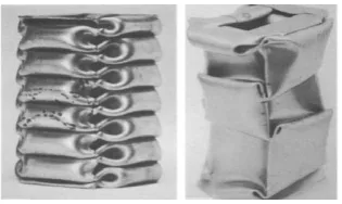
1.1 Axially crushed square tube in compact and non-compact mode (Reddy and Al-Hassani, 1993)
2
2.1 Circular aluminium tube 7
2.2 Square aluminium tube 8
2.3 Curve sections of initial phase and secondary (Dipaolo and Tom, 2006)
11
2.4 Graph of stress versus strain (NDT Resource Center, n.d.) 14 2.5 Point 1 is indicated as ultimate strength (Zaborski, n.d.) 15
2.6 Simple theoretical model for axisymmetric collapse (Alexander, 1960)
16
2.7 Relationship between generator shape and shape of load-deflection curve for axially symmetric buckling mode (Alexander, 1960)
17
2.8 A theoretical collapse model for non-symmetric mode; n=3 (Johnson et al., 1977b)
18
2.9 Force shortening characteristics of an axially compressed thin-walled aluminium column (Reid et al., 1986)
19
2.10 Compact mode (Reid et al., 1986) 20
2.11 Non-compact mode (Reid et al., 1986) 20
3.1 Flow chart of the methodology. 23
xiii
3.4 Dimensions of tensile test specimen 26
3.5 INSTRON 8872 Universal Testing Machine 27
3.6 Tensile test specimen is gripped tightly 29
3.7 Wood filling of circular tube 30
3.8 Wood filling of square tube 31
3.9 Preparation for cutting specimen 32
3.10 Water is put to reduce friction between blade and specimen surface
32
3.11 INSTRON Universal Testing Machines 5585 34
3.12 Sony Handycam Camcorder 34
3.13 Setup of equipments for compression test 35
3.14 Conduct of compression test 35
3.15 Results of compression testing 35
4.1 Tensile test specimens broken after testing 37 4.2 Example results of tensile test specimen 1 38
4.3 Tensile test specimen 1 39
4.4 Tensile test specimen 2 40
4.5 Tensile test specimen 3 40
4.6 Load-displacement curve of square hollow tube 200mm 41 4.7 Load-displacement curve of 50mm wood-filled circular tube 42
4.8 Load-displacement curve of 100mm tube 43
4.9 Sequence of configurations illustrating progressive crushing of a tube
45
4.10 Compressed circular hollow tube 48
4.11 Compressed circular hollow tube 49
4.13 Global buckling failure of 200mm tube 50
4.14 Mode of classification for circular aluminium tube (Guillow et.al., 2001)
51
4.15 Deformed mode of 50mm wood-filled tube 53 4.16 Deformed mode of 100mm wood-filled tube 53
4.17 Deformed mode of 150mm wood-filled tube 54 4.18 Deformed mode of 200mm wood-filled tube 54 4.19 Deformed mode of 200mm square hollow tube 55
4.20 Load-displacement curve of 200mm square hollow tube 56 4.21 Deformed mode of 50mm wood filled tube 59
4.22 Deformed mode of 100mm wood filled tube 59 4.23 Deformed mode of 150mm wood filled tube 60 4.24 Deformed mode of 200mm filled wood filled tube 60
xv
LIST OF ABBEREVATIONS
ASTM American Society for Testing and Materials
AutoCAD Auto Computer Aided Design
kPa kiloPascal MPa MegaPascal
GPa GigaPascal
UTM Universal Testing Machine LED Light Emitting Diode
J Joule
kJ kiloJoule kg kilogram
LIST OF SYMBOLS
D = Diameter t = thickness Y = yield strength H = tube length
E = modulus of elasticity
𝜎 = sigma
A = cross sectional P = magnitude of load Pmax = initial phase peak load
Pij = maximum and minimum load Pm = mean or average load
EAi = energy absorptions quantity H = plastic half fold length h = thickness
𝑀𝑜 = fully plastic bending moment per unit length
xvii
LIST OF APPENDICES
APPENDIX TITLE PAGE
A1 Gantt chart for PSM 1 77
A2 Gantt chart for PSM 2 78
B1 Deformation of 50mm wood-filled circular tube 80 B2 Deformation of 50mm circular hollow tube 81 B3 Deformation of 50mm square hollow tube 82 B4 Deformation of 50mm wood-filled square tube 83 C1 Results of compression test for 50mm circular hollow tube 85 C2 Results of compression test for 50mm wood-filled circular
tube
86
C3 Results of compression test for 50mm square hollow tube 87 C4 Results of compression test for 50mm wood-filled square
tube
CHAPTER 1
INTRODUCTION
1.1 Background
Nowadays, safe design of components and systems is an important issue in our
community. This is due to the purpose of decreasing the human suffering as well as the financial burdens on society. One of the awareness that increased among public is what can be
done in order to reduce the potential danger of impact dangers. One of the many types of tragedies like vehicle crash, the occupant safety is the main concern. So, the vehicle structures need to be designed well, acted as collision safety protection to absorb and dissipate the direct
impact force (Alghamdi, 2001). Thin-walled structures are widely used in the crashworthiness application such as automotive and aeronautical to withstand the impact force (Liu et al., 2015).
An energy absorber is a system that transform, fully or partially, kinetic energy into another form of energy. Thin-walled structures are good energy absorber due to the impressive folding deformation during axial compression (Alavi Nia and Parsapour, 2014). Techniques of applied
load, transmission rates, deformation patterns and material properties are the dependent variables for the conversion of kinetic energy into plastic deformation (Johnson and Reid,
1978). In addition, thin-walled structures are light weight, economic, high ductility and ease of manufacture. Since long time ago, there are many researchers had done the studies on how to enhance the energy absorbance and dissipation during crash via changing material
characteristic, geometry and type of filler.
2
static loadings, the square tube and circular tube will be collapsed in either concertina, diamond
or mixed mode. Basically, there are divided into seven categories such as sequential concertina, sequential diamond, Euler, concertina and diamond, simultaneous concertina, simultaneous diamond and tilting of tube axis (Andrews et al., 1983).
For these thin wall tubes, the filler such as solid wood can be combined with the tubes to stabilize and minimize the probability of the tubes to undergo Euler type of buckling. For
the square tubes and circular tubes that filled with solid wood, it has been proved that the solid wood is able to increase the stability of the tubes (Lampinen and Jeryan, 1982).
This is because the filling of solid wood enable the tubes to undergo higher plastic
deformation and higher energy absorption (Duarte et al., 2015).The solid wood is able to decrease the half-wavelength of the elastic buckling mode to values nearer to plastic fold
lengths. Therefore, the energy absorption capacity can be enhanced by eliminating the non-compact mode (Reddy and Wall, 1988).
The solid wood filled tube and the empty tube will be compared in terms of the peak
load, mean plastic half wavelength, energy absorption and the buckling mode (Florence et al., 1991). The energy absorption of the empty square tube and circular tube is roughly half of the
[image:21.595.218.376.622.716.2]energy absorption of the solid wood filled tube (Reid and Reddy, 1986). It is known that the interaction between the solid wood and the tube can provide a maximum benefit when there is an optimum combination (Reid et al., 1986).
1.2 Problem Statement
The impact of transport vehicles is an unfortunate but common occurrence. It is becoming apparent that, in the future, transport structures will have to be designed to withstand impact and crashes. The current trend in producing lighter structures but puts greater demands
on the designer since more aspects of design become critical as the weight is reduced, and working stresses become closer to the ultimate strength of the material. In the case of crash or
impact, the requirement is achieved through properly designed high absorption system. Thin-walled structure is always a good energy absorber but there is still insufficient to sustain the huge impact that acted upon it sometimes. So, the combination of the filler such as solid wood
with the tube is able to increase the energy absorption and prevent the happening of fatal accident.
1.3 Objectives
The objectives of this project are as follows:
1. To observe and study the deforming mode of empty and filled tube under axial loading
2. To determine the plastic wavelength and compare with theory
3. To study the load-displacement characteristics and lead to energy absorption
1.4 Scope of Project
The experimental project will focus on the empty and wood filled circular and square
4
experimental. Previous analytical work will be compared. Particularly in Euler Global bucking
CHAPTER 2
LITERATURE REVIEW
2.1 Introduction
This literature study is to find the relevant information that related on the solid wood filled tube under axial loading. The criteria that included in this chapter are energy absorber, deformation mode of empty tube, solid wood, uniaxial loading and mechanical properties.
2.2 Energy Absorber
Energy absorber is a device that able to absorb energy due to impact and dissipate it in other form of energy which is ideally in an irreversible manner. An energy absorber should be light in weight and able to keep the maximum allowable retarding force the same with the
greatest displacement. Tubes that will buckle in the progressive manner when subjected to axial compression is providing a cheap and good energy absorbing capacity (Jones, 2012).
Circular and square shape tubes are frequently preferred as energy absorber due to their common occurrence and easy manufacturability. For example, circular tubes can dissipate elastic and inelastic energy through different modes of deformation which show the different
response of energy absorption. Lateral compression, lateral indentation, tube splitting, tube inversion and axial crushing are the examples of the methods of deformation.