802.15.4e Sensor Network
.
White Rose Research Online URL for this paper:
http://eprints.whiterose.ac.uk/104557/
Version: Accepted Version
Article:
Al-Nidawi, Y, Yahya, H and Kemp, AH (2016) Tackling Mobility in Low Latency
Deterministic Multihop IEEE 802.15.4e Sensor Network. Proceedings of IEEE Sensors, 16
(5). pp. 1412-1427. ISSN 1530-437X
https://doi.org/10.1109/JSEN.2015.2500502
(c) 2016 IEEE. This is an author produced version of a paper published in Proceedings of
IEEE Sensors . Uploaded in accordance with the publisher's self-archiving policy. Personal
use of this material is permitted. Permission from IEEE must be obtained for all other
users, including reprinting/ republishing this material for advertising or promotional
purposes, creating new collective works for resale or redistribution to servers or lists, or
reuse of any copyrighted components of this work in other works.
[email protected] https://eprints.whiterose.ac.uk/ Reuse
Unless indicated otherwise, fulltext items are protected by copyright with all rights reserved. The copyright exception in section 29 of the Copyright, Designs and Patents Act 1988 allows the making of a single copy solely for the purpose of non-commercial research or private study within the limits of fair dealing. The publisher or other rights-holder may allow further reproduction and re-use of this version - refer to the White Rose Research Online record for this item. Where records identify the publisher as the copyright holder, users can verify any specific terms of use on the publisher’s website.
Takedown
If you consider content in White Rose Research Online to be in breach of UK law, please notify us by
Abstract—Providing reliable services for low latency (LL)
applications within the IoT context is a challenging issue. Several wireless sensor network (WSN) applications require deterministic systems that ensure a reliable and low latency aggregation service. The IEEE 802.15.4e standard, which is considered as the backbone of the IoT regarding WSN, has presented the low-latency deterministic network mode (LLDN) that can fulfil the major requirements of low latency applications. Meanwhile, several LL applications, for example in the automotive industry, demand the support of sensor node mobility which in turn affects network performance. Node mobility triggers several dissociations from the network that will increase latency and degrade node throughput. In this paper, we investigate the impact of node mobility over the LLDN mode while defining key factors that maximize latency and degrade throughput. In addition, an enhanced version of the LLDN mode is presented and evaluated that supports node mobility while maintaining the targeted limits of LL application requirements. The proposed mobility aware (MA-LLDN) technique manages to reduce the dissociation overhead by a factor of 75% while the packet delivery ratio (PDR) has been enhanced by 30%. Furthermore, this paper presents an analytical model that provides a snapshot of the tradeoff process between different metrics in the IEEE 802.15.4e LLDN design, which must be considered prior network deployment in mobile LL applications.
Index Terms—Low Latency; IEEE 802.15.4e; LLDN; nodes
mobility; Markov chain; multihop.
I. INTRODUCTION
EVERALstandardization efforts are collaborating to shape the concept of the internet of things (IoT). Within the WSN field, three standardized elements are merged to facilitate the integration of WSN into the IoT world. These elements are the IEEE 802.15.4 [1], 6LoWPAN [2] adaptation layer and IPv6 protocol [3]. IEEE 802.15.4 here is acting as the backbone of the IoT, from the WSN’s perspective, by which it provides the physical and MAC infrastructure of the IoT paradigm. Hence, optimizing the IEEE 802.15.4 standard performance has major advantages that could influence and contribute to the integrity of the IoT functionality. One of the
Yaarob Al-Nidawi, Harith Yahya and A. H Kemp are with the Electronic and Electrical Engineering Department, University of Leeds, LS29JT, UK,(e-mails:[email protected]; [email protected]; [email protected]).
application types that need to be addressed carefully is the LL applications. These applications must be considered by deterministic systems that ensure minimized latency in order to maintain network reliability and availability. Thus, the IEEE 802.15.4 has presented the LLDN within the first amendment (IEEE 802.15.4e MAC sublayer) [4]. The LLDN objective is to facilitate aggregating data sensor nodes within a time window of no more than10ms1. However, default LLDN mode specifications cannot fit the requirement of all the addressed LL applications due to several constraints. Applications like automotive manufacturing, health applications (wearable sensors [5]), cargo containers [6], remote goods tracking [7], airport logistics and portable machine tools all encompass the mobility feature. Sensor nodes movement within a deployment field needs to be addressed carefully by ensuring two important parameters; (i) full area coverage to ensure the entire sensing area field is covered by multiple coordinators and to eliminate any coverage black holes, (ii) all the nodes must have a reliable, lightweight and fast mobility management scheme that minimizes the required time to associate with a new coordinator.
Under the IoT umbrella, node mobility can be handled by three different approaches based on the network stack layer that will accomplish this task. Hence, it can either be managed through IEEE 802.15.4e, 6LoWPAN or the IPv6 protocol (i.e. MIPv6). Prior to devising the layer that should be assigned to tackle the mobility issue, we have to determine the type of node mobility in order to consider the optimum approach. According to [8], the node mobility can be distinguished into two types; micro and macro. The micro mobility refers to movement inside a single network domain while the macro mobility corresponds to the node movement between different network domains. Accordingly, since we are mainly dealing with a micro mobility scenario, then at this stage it’s better to omit the IPv6 approach in order to minimize the incurred overhead of the utilized scheme like MIPv6 [9] (as it is considered a complicated protocol for low power devices [10]) and eliminating its burden on the nodes. The second tactic is relying on 6LoWPAN, but unfortunately this adaptation layer diverts the mobility issue to the responsibility of the routing protocols [11]. Alternatively, the remaining solution focuses
Tackling Mobility in Low Latency
Deterministic Multihop IEEE 802.15.4e Sensor
Network
Yaarob Al-Nidawi,
Student Member, IEEE
, Harith Yahya,
Student Member
,
IEEE
, and Andrew H.
Kemp,
Member, IEEE
S
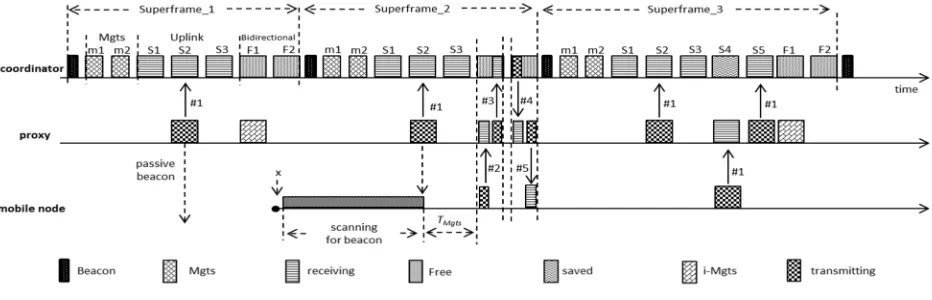
on the IEEE 802.15.4e standard and specifically the LLDN mode itself. Accordingly, the objective of this paper is to study the impact of mobility on the LLDN mode via presenting a Markov chain model that addresses the possible states a mobile node might encounter through the association process. In addition, we are introducing a mobility-aware (MA) LLDN scheme that considers the nodes mobility problem and minimizes both latency and energy consumption while maintaining the possible assumptions that the LLDN has stated. Furthermore, the proposed MA-LLDN supports multihop topology to extend the coverage of the coordinator while omitting the need for deploying further coordinators in the network. In turn, this minimizes the deployment cost and the probability of beacon collision between adjacent coordinators. The proposed approach has low latency since it delivers the readings within the same superframe. The relay nodes also act as a proxy to the coordinator where they can passively indicate the existence of the coordinator with low overhead and less association delay.
The remainder of this paper is structured as follows. Section II provides a description of relevant related work leading to an explanation of the infrastructure of the LLDN mode in section III and then section IV analyses the mobility overhead. The novel proposed MA-LLDN which tackles the impact of node mobility, is presented in section V. Analysis and discussion of our results are presented in section VI before conclusions being drawn in the final section.
II. RELATED WORK
In a static network, the sink mobility (which can be considered here as the coordinator mobility) is said to be a solution to enhance network performance. Accordingly, to minimize the latency and energy consumption, a mobile sink is deployed that circulates through the network to collect readings as in [12-15]. Other literature addressed the issue of latency in sensor network but do not address the mobility nor are dedicated for the IEEE 802.15.4 standard [16-19]. Similarly, the recent contributions that concern the LLDN do not consider the mobility issue. Therefore, a significant part of the IoT paradigm, which is the IEEE 802.15.4e LLDN mode, has not been addressed before and needs to be evaluated comprehensively to optimize performance with regards to sensor node mobility.
Here the current enhancements to the default LLDN structure are introduced.
A. Bergeret al. [20] improve data collection reliability of the default LLDN star topology by amending the structure with relay nodes. The objectives behind the relay nodes are to increase the transmission reliability via retransmitting unsuccessfully delivered packets and to extend the topology to two-hop networks. The authors indicate that the coordinator is stationary while the nodes might be mobile but did not address the issue of association since the target of the paper is realizing reliable transmission and 2-hop communication. The authors amended this work and improve its reliability in [21] through utilizing the combinatorial testing approach (CT) which is described in [22].
G. Pattiet al. [23] introduce the multi-channel approach to reduce operational cycle times (superframe size). Maximizing the number of nodes increases the cycle time linearly, and hence the authors have divided the network into clusters (called subnetworks). Each cluster will have a different frequency channel to simultaneously operate without any interference with other clusters. Although this approach will minimize the cycle time for the individual subnetwork, but still the head coordinator operates for a full cycle related to the number of nodes in the total subnetworks that are connected to it.
L. Dariz et al. [24] improve LLDN performance via optimizing the LLDN superframe duration. This is achieved through turning the timeslot allocation procedure into a flexible and efficient allocation process. Instead of fixing the number of base timeslots in the uplink and downlink slots to a fixed size in the superframe, the number of base slots will be variable based on each node’s requirement. In addition, the authors amended the superframe structure to accommodate more slots types as high-priority uplink and high-priority downlink slots to fulfil the requirements of some nodes with high priority data.
M. Anwar et al. [25] provide an analysis for different LLDN configuration parameters during network control design. The analysis takes into account different LLDN configuration parameters such as base timeslot size, superframe size, enabled security or not and payload size. The target is to provide a tradeoff between LLDN configuration parameters that will aid the LLDN network control design phase.
H. Kapil et al. [26] incorporate node relay placement strategy and error correction technique to minimize the number of retransmissions and hence, a reduced number of relays and better energy efficiency. The objective of the proposed approach is an adaptive retransmission technique by integrating a Reed Solomon error correction scheme with a relay placement mechanism (that is based on the rainbow ranking algorithm [27]). The advantage is less nodes and less energy consumption while high LLDN reliability is achieved.
III. LLDNDESCRIPTION
relying on the timeslot (TS) index inside the superframe to determine the sender node identity. Hence, this eliminates CSMA-CA delay (caused by the contention process during eachTS) and reduces transmitting/receiving time delay.
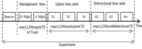
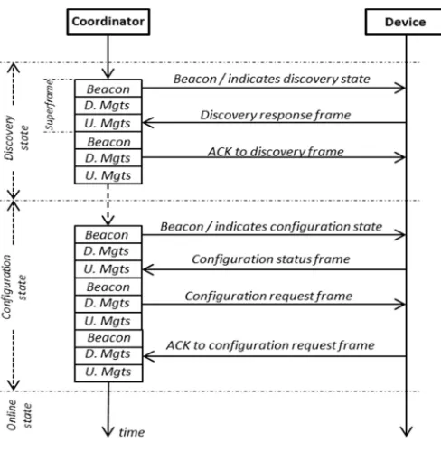
The LLDN mode has three distinct transmission states and each has predefined superframe structure and purpose. The first transmission state is the discovery state that is initiated either during the network setup or to handle new node association to the network. The second phase is the configuration state, by which the nodes that managed to communicate with the coordinator during the discovery state shall receive network configurations during this state. The last state is the online, where the nodes can transmit their readings to the coordinator within the assigned timeslots during the configuration state. The coordinator specifies the state of transmission through the periodically transmitted beacons. Each one of the discovery, configuration and online states has a defined number of superframes during its period that will be defined by the network administrator; nSD, nSC and nSO
respectively as in Fig. 1.
The discovery and configuration states share the same superframe structure but with different network purposes. The discovery and configuration superframes contain only one beacon slot and two management TSs (uplink and downlink). Although the online superframe has beacon, management, uplink and bidirectional slots, the default setting has omitted both management and bidirectional slots (asmacLLDNmgmTS
is set to FALSE and macLLDNnumBidirectionalTS is set to zero). Beacons are broadcast periodically and used to synchronize the nodes, identify the present transmission state and contain an acknowledgment bitmap of the previous superframe received readings. The uplink management TSis utilized by dissociated nodes during discovery and configuration transmission states to transmit discovery response frame and configuration status frame respectively. During the downlink management slot, the coordinator shall respond to nodes’ requests by either replying ACK messages (within discovery state) or configuration request frame (within configuration state).
Uplink timeslots are unidirectional (from nodes to coordinator) and the default number ofTSs in the uplink is set to 20 (based on the macLLDNnumUplinkTS value) and its maximum value is 255. Transmission failure can be refreshed by permitting the nodes to retransmit within the next superframe and defined by the macLLDNnumRetransmitTS,
which specifies the number of retransmission timeslots within uplink section. The bidirectional section has
macLLDNnumBidirectionalTS timeslots and the direction of
transmission is indicated within the beacon fields. Fig. 2 indicates the basic layout of a general LLDN superframe structure.
Nodes seeking to join the network must follow a sequence of association steps determined by the transmission state of the upcoming superframes. Each node wishing to associate with the network must scan for beacons to determine both the existence of a coordinator and the transmission state of the current superframe. Once it has received a valid beacon that indicates a discovery state, the node sends a discovery response frame to indicate its willingness to join the intended coordinator as indicated in Fig. 3.
A node can transmit its request only during the uplink management slot (its time is defined through the beacon). The management TSs are treated as shared group TSs and the nodes commence transmission based on a simplified CSMA-CA. If the coordinator receives the request correctly, it will reply with an ACK message during the downlink TS of the next superframe. Each coordinator waits for
macLLDNdiscoveryModeTimeout seconds until changing to
the configuration state if no discovery response frames are received. The association process will transfer to the second phase if the coordinator indicates the configuration transmission state through the announced beacon. Once a node indicates this state, it sends a configuration status frame (during the uplink management TS) to request network configuration parameters. The correspondent coordinator will reply with a configuration request frame that contains the assigned timeslot, its duration, transmission channel and any related information based on the network settings. Finally, the node receiving the configuration request frame replies with an ACK message to confirm successful configuration.
Studying the infrastructure of the LLDN can conclude several issues that rose by the association process and are escalated with the presence of mobile nodes. These drawbacks can degrade the network performance and violate the objectives that the LLDN is based on to support LL application limitations. We can summarize these issues into the following:
- There is no mechanism to change from transmission state to another after the network initialization phase. - During the online state (which is the dominant state
[image:4.612.85.241.50.189.2]through the network lifetime) any node seeking to join the network has no feasible procedure to communicate with a coordinator, especially with the
[image:4.612.313.561.57.143.2]Fig. 2. General LLDN superframe structure
macLLDNmgmTS is set to FALSE during online state.
- The size of the management TSand the contention mechanism must be reconfigured to accommodate multiple orphan nodes (or mobile nodes seeking to join the network) and minimize the dissociation time to reduce latency.
- In order to commence the association process, the network must transit to the discovery state and drop the online state. This means preventing the connected nodes from transmitting regular readings and wait till completion of both discovery and configuration states. This increases latency and violates the objectivity of LLDN which can get worse in the case of high mobility, where the network has several transitions from the online state to other states. - The LLDN is based on a simplified CSMA-CA
where themacMaxCSMABackoffsvalue has been set to zero. This complicates the association process due to the announcement of a channel access failure after only a single unsuccessful CCA scan. Hence, the node has to scan for another beacon and superframe, which will maximize the dissociation interval. - The default assumption of the LDN is based on a star
topology that considers single-hop scenarios, whereas in reality and for multiple application types a multihop infrastructure is required. Considering a single hop infrastructure for highly dense network, with mobile nodes and short range transmission can cause a flaw in the design phase. First, due to the increased required numbers of coordinators in order to assure single hop transmission, this will in turn increase deployment cost and complexity. Second, this will maximize the number of dissociations due to short range transmissions and high number of mobile
nodes. This maximizes the latency and degrades network availability.
IV. MOBILITY OVERHEAD OVERIEEE 802.15.4ELLDN
The impact of node movement and the overhead upon the network performance need to consider the lifecycle of a mobile node. The possible life stages that a mobile node encounters since deployment can be categorized into four basic steps as explained in Fig. 4. Based on this classification, we can estimate the elapsed time in each state. From this point, we have to define the possible time duration of each superframe type in LLDN, as for each transmission state there will be a different superframe duration. Discovery and configuration superframe intervals are closely related where the discovery superframe interval (SD) can be defined as:
= + ( × 2) + ( )
BP is the beacon period in symbols and corresponds to
physical header plus MAC header lengths (in bytes) and is multiplied by the number of symbols per byte (for the 2.4 GHz band both physical and MAC are 2). TSZ is the real slot size
(excluding interframe spacing) of a slot and the SIFS
corresponds to macMinSIFSPeriod while RS is the symbol
rate. PA is the interval time between each beacon
announcement, since the network administrator may extend the period between each superframe (in our calculationPA is
set to zero) to utilize energy (wherePAis the inactive period).
The BPcan be estimated to be (6+7) ×2 symbols and TSZ is
equal to (6+4+14) ×2 symbols, where the maximum payload (in the discovery stage messages) is 14 bytes. In addition, configuration superframe duration (SC) can be estimated as:
= + ( × 2) + ( )
WhereTSZ here is equal to (6+4+14+additional_payload)× 2
and LIFS corresponds to macMinLIFSPeriod.
additional_payload depends on the application and could be
the frequency channel, assigned timeslot etc.
Finally, online superframe (SO) can be estimated as indicated
in [4] while identifying the MAC payload size:
= ( )
WhereNTS represents the possible number of timeslots in the
(1)
(2)
[image:5.612.66.310.48.298.2] [image:5.612.334.552.50.189.2](3) Fig. 3. Association procedure in LLDN
2
2 +
( )/
( )
+ ( )
+ ( × ) + ( × )
2
uplink unidirectional field and can be either set to
macLLDNnumUplinkTS value or can be varied based on the
number of nodes in a POS. HereTSZis the actual slot size of a
single base timeslot (excluding interframe spacing) in the uplink and equal to (6 + 3 + payload_size) × 2. Table I
presents a list of symbols and their definitions used in this paper, while Table II illustrates the utilized MAC attributes.
As in Fig. 4, there are four states that a mobile node may encounter, scanning for beacon interval (SCB), requesting
association (ASTreq), fully Associated to network (AST) and
indicating disconnect (Dis) (or orphan).
The first phase of this lifecycle that will be estimated isDis, where it can have two values based on the methodology followed to indicate the dissociation (announce the node is orphan), which is either based on the number of lost beacons or missed ACK messages.
= ×
×
nmACK represents the number of missed ACK messages.
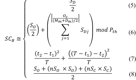
Regarding the second phase, scanning for beacon interval (SCB) can be expressed as:
In these four scenarios, (5) is the case where the coordinator is in the discovery transmission state. Here we are assuming perfectly scheduled timeslots, but in the case of different superframes durations, it will follow the random incidence paradox [28, 29] and expressed as:
[ ] 2 [ ]
But since we are dealing with tightly synchronized nodes, Attribute Definition
macLLDNmgmTS Indicate the existence of management
timeslots (Boolean value)
macLLDNnumBid-irectionalTS
Number of bidirectional timeslots
macLLDNnumUp-linkTS
Number of uplink timeslots
macLLDNnumRet-ransmitTS
Number of retransmission timeslots
macLLDNdiscove-ryModeTimeout
Time threshold to change form discovery to configuration state
macMaxCSMABa-ckoffs Maximum number of backoffs the CSMA
can attempt
SIFS Short interframe space
macMinSIFSPeriod Defined value ofSIFSin the standard
LIFS Long interframe space
macMinLIFSPeriod Defined value ofLIFSin the standard
aMaxLostBeacons The maximum value of missed beacons to
announce the node is orphan
aTurnaroundTime Required time for a device to change from
transmit to receive state and vice versa TABLE II
IEEE 802.15.4EMAC ATTRIBUITES
(9) (5) (4)
(6)
(7)
(8) Symbol /
Abbreviation Definition
ASTreq Requesting association
AST Associated to the network
Adi representsithadjacent POS
BP Beacon period
BE Backoff exponent
CW Contention window length
Dis Indicating dissociated
Dm Density metric
D Distance
D_Mgts Downlink management timeslot
Ethr effective throughput
h Hop index
i-Mgts Image of a management timeslot
K Possible number of movements inside a POS
Lh latency in a given hop
LD Expected latency during discovery state
LC Expected latency during configuration state
LCA Expected latency during acknowledging configuration
state
LosD number of lost data frames
Mm Mobility metric
Mgts Management timeslots
Nm number of mobile nodes seek to associate the coordinator
Ncrt set of existed nodes in a POS
NA set of active nodes
Na(i) number of nodes get associated at a given timeti
Nw Number of nodes waiting to associate
nSO the number of online superframes
nSD the number of discovery superframes
nSC the number of configuration superframes
nPh number of mobile nodes attached to a given proxy
Oc preferred number of online superframes
PA Interval time between two beacons
Pth Maximum number of online superframes
R Transmission range
Reqs Maximum configuration request size
RS Symbol rate
Rt Total running time
S Superframe in general (any superframe type)
SD discovery superframe interval
SC configuration superframe interval
SO online superframe interval
SCB Scanning for beacon phase
SBmgts Size of a single slot in Mgts
TS Timeslot index
TSZ Timeslot size (excluding interframing space)
Tack Turnaround time
TMgts Time counter after what the proxy node accepts
association request
ts Settle time in a POS
U_Mgts Uplink management timeslot
Vx(t) velocity of nodexat timet
xD number of mobile nodes successfully transmitted
discovery response frame
D Probability of the first CCA returns free (during discovery state)
Probability of receiving a beacon
probability of a received beacon determines discovery
state
D Probability of the second CCA returns free (during discovery state)
[image:6.612.338.561.498.630.2]t Probability to complete association withints
TABLE I
(12) perfectly scheduled and fixed superframes duration are
assumed, soSCB= (S/2), whereSis any superframe (SD,SCor
SO). In the case of the coordinator in the online state, the
scanning and waiting time is dependent on the interval that is adjusted to transfer from the online to discovery state as in (6). The approximated scenario is to harness both the mobility metric (Mm) and density (Dm), which can be derived both
based on [30, 31] and [32] respectively, to determine the duration between each transfer. Oc represents the preferred
number of online superframes in each period before flipping to a discovery state whilePthis the maximum number of online
superframes after which there must be a discovery state. Based on these parameters it will be easy to efficiently provide a tradeoff between latency and dissociation time, increasing mobility and density metric will increase the number of discovery superframes per online superframes in order to accommodate more mobile nodes and reduce the scanning waiting time. According to [31], the mobility metric can be considered as the average relative speed of nodes over the possible number of node pairs and running time. Hence, for a given graphG= (N, P), whereNis a set of sensor nodes andP
is a set of links between the nodes and N, the mobility metric
Mmcan be expressed as [30, 31]:
= 1 | |
1
| ( ) | | |
| |
WhereRtis the total running time,Vx(t) is velocity of nodexat
timet. In addition, according to [32] the density metricDmcan
be expressed as:
= | |
HereAis the scattered area andRis the transmission range. Returning to (7), which holds the condition that two coordinators exist, for a given period of time T. If the first coordinator announces att1and the second announces att2and
t1,t2 T, then we have two inter-arrival times, (t2-t1) and ((T
-t1)-t1). Thus, the expected waiting time can be expressed as in
(7).
The fourth scenario, as in (8), is applied when there is a defined structure of the network transmission states. The scanning time in this condition is based on the number of online superframes (nSO) and the number of configuration
superframes (nSC) that are both defined prior to network
deployment.
The third phase of the mobile node lifecycle is theASTreq,
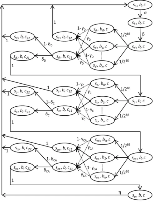
which will be completely dependent on the ratio of the number of both discovery and configuration superframes to the online superframes. In addition, it will follow the impact of the number of mobile nodes entering the same POS at the same time besides the nodes speed and transmission range. Hence, Fig. 5 presents a Markov chain that models the possible states for a mobile node during the association process. A mobile node’s condition can be described in three stochastic processes; node status, backoff condition and CCA outcome (s(t), b(t) and c(t) respectively). The possible states of s are orphan, received beacon, discovering, configuring,
configuring_ACKing and associated, which will be presented ass= {sO,sD,sC,sCA,sA}. Meanwhile,b will be varied in the
range [0, 2BE-1] and presented as b = {b0, b1, …, bn}. The
backoff exponent, BE, will be set to macMinBE value. Finally, c represents the possible states of the two CCA processes as CCA1_free, CCA1_busy, CCA2_freeand CCA2_busyand
presented as c= {c11, c12, c21, c22}. The probability ( ) of
receiving a valid beacon depends on the amount of coverage percentage within the scattered area (there is an adequate number of coordinators to cover the whole area of deployment). In this paper, we will always assume that we
have a well scattered deployment, =1. The probability ( ) of
the received beacon in determining a discovery state will base on the adjusted ratio of discovery state to other transmission
states. During the network initialization period, =1 for at
least a period ofmacLLDNdiscoveryModeTimeoutif no node requests association. Meanwhile, within the network steady
state period, can be expressed as:
)
Where, xD is the number of mobile nodes that have
successfully transmitted discovery response frames and received ACK messages. The probabilities of the first CCA
and second CCA (during discovery state) ( D, D) returning a
free channel within a givenBEvalue (bi) are expressed in (13)
[image:7.612.319.566.53.381.2]and (14) respectively.
Fig. 5. Markov chain for mobile node transitions in LLDN
(14) (13) ( )=
(2 )
(2 )
1
= 1
( )
WhereNmcorresponds to the number of mobile nodes seeking
to associate with the coordinator within the same superframe and can be derived as:
= | | + + | |
Ncrt is a set of existed nodes in the POS and NAis a set of
active nodes, whereNA Ncrt.Adirepresentsithadjacent POS
andjis the total number of adjacent POSs,Nwis a set of nodes
already in the POS and waiting for the discovery state.
Moreover, during the configuration state, the probabilities of
the first CCA and second CCA ( C, C) returning a free
channel are expressed in (16) and (17) respectively.
( )=
(2 )
(2 )
1 ×
= 1
) ( )
XDdenotes the number of nodes managed to receive ACK for
the discovery response frame. Finally, the probabilities of the
first and second CCA ( CA, CA) returning a free channel in the
acknowledgement phase of the configuration state are as follow:
( ) =
(2 )
(2 )
1 ×
= 1
) ( )
XC denotes the number of nodes which managed to receive a
configuration request frame.
Accordingly, we can calculate the relevant probabilities of each transmission mode to conclude the probability of associating to a coordinator. The probability of receiving an ACK message during the discovery state is:
( , , | , , ) = 1 2
And the probability of receiving the required synchronization information during the configuration state is:
( , , | , , ) = ( , , | , , ) 1 2 Finally, the probability of associating to the coordinator is:
( , , | , , ) = ( , , | , , ) 1 2 The latency during either discovery or configuration state is determinant on the number of mobile nodes, since (as in the
standard) we assume that the coordinator shall stay at each state until responding to all requested nodes within POS. Therefore, ASTreq can be derived based on the incurred
expected latency at each state. The expected latencies (LD),
(LC), (LCA) during the discovery, configuration and
acknowledging configuration states respectively can be estimated as:
( ) =
( , , | , , ) ( , , | , , ) ( × )
( ) =
( , , | , , ) ( , , | , , ) ( × )
( ) =
( , , | , , ) ( , , | , , ) ( × )
Hence, the expected waiting time during the association request phaseASTreqis:
= + +
On a second hand, in order to determine a successful association, the required time to associate must be less than a settle time (ts) in a POS. Thus, the probability ( t) to complete
association is:
+ +
The ts parameter is dependent on several elements as node speed, possible trajectories inside a POS and coordinator coverage. Therefore, for a mobile node under the random waypoint mobility scenario, there will be three basic elements; node speed, possible moving distance and pause time. For a node speedsp in the range [sp1,spn], distanceDin the range
[d1, dn] and pause time p in the range [p1, pn], the expected
settle time can be defined as:
= [ ]
[ ] + [ ]
=
1
1 +
1
Hence, settle time is:
=
+ 2 + 2
+ +
2
Wherekis the possible number of movements (or the possible epochs before leaving POS) and is affected by the transmission range of the coordinator andD. In this work we (15)
(16)
(17)
(18)
(19)
(20)
(21)
(22)
(23)
(24)
(25)
(26)
(27)
(29)
(30)
(31)
(32)
(33)
(34) are not interested in investigating the stochastic features of the random waypoint mobility model while a comprehensive analysis can be found in [33, 34].
The probability of leaving the POS ( ) will be dependent on
the transmission range (R) of the sensor nodes and the total number of movements inside a given POS (assuming a straight line trajectory in a POS), expressed in (29).
1
2 [ ]
For a better network performance in a mobile sensor network environment, a dissociation function must be introduced, which is a measure of the number of nodes that are dissociated. Thus, the target of a mobile sensor network must always seek for low dissociation function to gain high network connectivity and availability. This measure can be derived based on the Kaplan-Meier estimator [35]. Thus, forndistinct event timest1<ti< … <tn, the dissociation function ( (t)) for
a total timet,thatt1,ti, …,tn t, can be expressed as in (30).
Where,Na(i) represents the number of nodes get associated at
a given timeti.
Ŝ( ) = ( ) ( )
( )
One of the issues that need to be highlighted is the node throughput that is crucial for several sensor network applications, especially that requires streaming [36, 37]. The throughput of LLDN network is related to the amount of time that the coordinator is within the online state. Therefore, we have to estimate the number of lost data frames (LosD)
after each transfer from the online to other states, which can be expressed as:
= × + ×
In the meantime, the effective throughput (Ethr) in (bps) of
the network can be defined as:
= × 8 × + ×
×
Where nSOis the number of online superframes and the data
payload (MAC service data unit, MSDU) is the actual payload data size in octets as defined by the standard.
Furthermore, the packet delivery ratio (PDR), which is related to the impact of dissociation, during a giventstime can be expressed as:
= + +
The impact of transferring each time from the online state can lead to PDR degradation and can be calculated as:
V. PROPOSEDENHANCED ANDMOBILE-AWARELLDNSCHEME
From the previous sections, we can conclude two main requirements to achieve better network performance, which are low latency and multihop infrastructure. Since the LLDN is designated for a star topology, then there must be a mechanism to facilitate the multihop feature which supports both node mobility and LL. Comparing the star topology to other different topologies for the case of IEEE 802.15.4 infrastructure, it has less latency but unfortunately has less success probability [38]. Conversely, if we are looking for low dissociations, then the network has to be assisted with multiple coordinators to guarantee low waiting time prior to achieve association. This led us to the strategy of increasing the number of coordinators, but this will unfortunately open the gate to another issue, which is the overlapped beacons collision. Beacons of adjacent coordinators collide due to overlapped communication range and this issue has been addressed in several work [39-41]. Therefore, the objective of the proposed approach here is:
- To minimize the dissociation time and increase the mobile node connectivity.
- Determining how the latency and collision can be minimized.
- To support a multihop paradigm while omitting extra coordinators.
- Combining the advantages of both tree and star topologies?
A comprehensive analysis in [38] shows that the tree topology outperforms the star topology in terms of transmission success probability, but the problem with a tree strategy is significant latency. Thus, we have to figure out an approach that provides multihop (tree infrastructure) while minimizing the encountered delay. One of the approaches that could be utilized is clustering [42, 43], this technique is suitable to minimize the impact of collisions and maximizes transmission success rate but in turn increases the latency in the tree infrastructure. Hence our problem must be tackled through modifying the existed LLDN superframe infrastructure. Accordingly, the proposed approach is based on two principles; first, defining the concept of proxy coordinator and the notion of passive beacon and second, modifying the LLDN superframe.
(35)
(36)
(37) A mobile node that can’t detect any beacons, can listen for
existing data frames and scan the header for the preamble byte. If preamble_1 exists, then the next byte is the time (TMgts) by which the proxy node is accepting association
requests (see Fig. 6). TMgts is the time interval between the
transmitted data frame and the time a proxy switches the radio on to receive a request. In order to mitigate any chance of collision with the coordinator, the proxy utilizes the F slots (additional free slots the coordinator allocates for the purpose of permitting proxy node to accept association requests freely). Each proxy adjusts the time to accept association requests within defined slot boundaries (called image timeslot
(i-Mgts)) that coincide with the first bidirectional (F1) slot in
the superframe. The duty of the coordinator in this case is to ensure that there are always at least two free F timeslots in the bidirectional field of the superframe to be used by the proxy nodes. This will ensure that the management timeslotsi-Mgts
(of proxies) are not overlapping with the current utilized (transmitting data) slots in the superframe. The bidirectional slots will always be used as the first n/2 slots as uplink and the second n/2 slots as downlink, for slots [F1-Fn], where n here is the number of slots in the bidirectional field.
Once a proxy receives an association request (message #2 in Fig. 6) during the i-Mgts, it will relay the request to the coordinator within the same slot (message #3), since this slot has been freed within the superframe for the purpose of this task. During the next timeslot, the coordinator responds with the required information (message #4) in order to synchronize the mobile node (allocated timeslot, transmission channel, etc.). The proxy has to relay the information back to the mobile node (message #5) and finalize the association process. Hence, the entire process is accomplished within only two consecutive timeslots (in the case of two hops).
The coordinator upon the addition of a new mobile node, adds four additional timeslots to the uplink and bidirectional fields for each upcoming superframe. That will be one for transferring data from mobile node to proxy (slot S4), one for transferring data from proxy to coordinator (slot S5) and two (slots F1 and F2) for the purpose of i-Mgtsslots. Thei-Mgts
slots are harnessed by the proxy nodes to permit more mobile nodes in the future to join the network.
The modified superframe has reduced the latency by instructing the proxies to relay the data frames of the nodes,
which are not within the first hop, within the same superframe. Hence, the latencyLhfor a node in a given hop (h) is:
Lh[min]andLh[max]can be calculated as:
=
( )
2 + ( )
=
( )
2
( )
2
( )
Where the IFS corresponds to the interframe spacing that could be either macMinSIFSPeriod or macMinLIFSPeriod.
nPhrefers to the number of mobile nodes attached to a given
proxy (within the route) at hoph.
Since the maximum configuration request size (Reqs) is 48
symbols (physical and MAC header plus configuration status payload), then the required time to commence transmission of two messages is always less thanTSZ. Hence, a single timeslot
TSZ in the uplink filed of a superfame can accommodate two
transmissions, sending an association request and replying with an ACK message. Thus, this property will be always true:
ACKsis the ACK message size which can’t exceed 48 symbols
(physical and MAC header plus configuration request payload) and Tack is the turnaround time and corresponds to
aTurnaroundTime value, which is 12 symbols. According to
the standard, the required time for a node to switch from receive to transmission mode and vice versa is equal to
aTurnaroundTime symbols. Thus, we include it in our
analysis.
Considering more than two hops is also still feasible, but the coordinator must provide at least four F slots in the bidirectional field to accomplish an association. This is caused by the TSZ size limitation, where it is impossible to handle
[image:10.612.79.545.50.200.2]three transmissions in a singleTSZ. The required time is larger
(38) the size of individualTSZ:
Therefore, for 3-hops and 4-hops mobile nodes, the coordinator has to allocate at least four slots to complete the association process as in Fig. 7. The coordinator must be adjusted based on the number of permitted hops in the network. Hence, for a network that allows for three hops, the coordinator is forced to allocate four slots [F1-F4] in order to guarantee smooth mobile node association.
Seeking to avoid the hidden-node problem [44, 45] in multi hop networks, transmitting regular readings to the coordinator must be accompanied with the allocation of extra slots to the superframe. These slots will be called “saved” and the coordinator may stay inactive during these slots to save energy. The saved slots are required for the purpose of transferring data between mobile nodes and proxies as in {S4} in Fig. 6 and {S4, S5, S6} in Fig. 7.
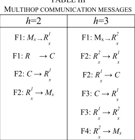
For a given network, if hop h=2 the set of proxy nodes
Prox2=[R
2 1-R
2
n] and ath=3 the set of proxiesProx3= [R 3 1-R
3 m
]. Then we can describe the negotiation between a given mobile node Mx, proxy and coordinator C during the
association phase ath=2 andh=3 as in Table III.
Regarding the case ofh=4, it will still be feasible to conduct the association within four slots [F1-F4] due the property of (38).
There are two important drawbacks in the structure of the LLDN. The first one is its dependency on three transmission states and the second is the sequence of the Mgts in the superframe. The first issue is caused by the types of transmission states which influence two crucial aspects in the network, throughput and association. The throughput is affected due to the transfer from the online state to other states, which will make the nodes refrain transmitting data until the coordinator switches again to the online state. The association issue has already been indicated previously in sec. III. Accordingly, the first enhancement can be achieved through swapping the D_Mgts with the U_Mgts. Therefore, the coordinator can reply within the same superframe to the
Thus, during U_Mgts, the mobile node requests association and the coordinator responds immediately at D_Mgts. The second enhancement can be realized through modifying the structure of Mgts. These two slots must be existed in each superframe and not optional as indicated by the standard, at least the superframe includes theMgtsin every period of time that corresponds to the mobility metric. In addition, in order to preserve network throughput and to minimize the dissociation time, the structure of the transmission states must be altered. According to the LLDN, the nodes can only associate through the sequence of discovery then configuration states. These two states can be observed during the initialization phase of the network while during the steady state and since we already force the coordinators to keepMgtsin each superframe, these states can be omitted. Hence, the network keeps operating inside the online state without switching to other states and considers the Mgts to accomplish the required association process, as indicated in Fig. 6 and 7.
For limited power coordinators and multihop network, there will be some limitations regarding beaconing. This affects the period of beaconing and then maximizes the superframe duration SO. This issue also can be caused by increasing the
number of LLDN devices within the POS that in turn maximizesSO. In this case,NmandSOinfluence the number of
nodes Nw waiting to associate and this value could be
increased as the coordinator increasesSO.Thus, there must be
[image:11.612.367.503.255.396.2]a mechanism to facilitate multiple mobile nodes associations within the same superframe. In addition, restructuring the Fig. 7. 3-hops mobile node association in MA-LLDN
h=2 h=3
F1:Mx R1
x
F1:R C
F2:C R1
x
F2:R1
x Mx
F1: Mx R2
x
F2:R2
x R
1
x
F2:R1
x C
F3:C R1
x
F3:R1
x R
2
x
F4:R2
x Mx
TABLE III
Mgtsto accommodate multiple nodes and maintain these slots properly will preserve the functionality of the Mgts as dedicated by the standard which can be utilized for other purposes instead of association. Therefore, a backoff mechanism is proposed in this paper to manage mobile node access duringMgts.
The backoff technique relies on amending theMgtssize that can be achieved through utilizing the timeslot size field in the beacon. In addition, bits 5-7 in the flag fields of the beacon are utilized to define the number of base time slot in each Mgts. Hence, we can construct the Mgtsas a slotted access field by which it can resemble the contention access period (CAP) in the beacon enabled mode. The size of each slot (SBmgts) inside
theMgtscan be estimated to be (in symbols):
SBmgts =Max_Backoff_Time+Total_CCA_duration
+Maximim_transmission_time+SIFS
[(2 ) × 20] + (2 × 8) + 48 + 12 Hence, the maximum SBmgts size can be 216 symbols. The
maximum transmission time has been set to 48 symbols with the assumption that the association request payload contains (full address, short address and 4-Byte for application-specific purposes). The proposed backoff mechanism is an amended
version of the simplified CSMA-CA and the number of contentions is limited by the number of slots in a singleMgts
(nSBmgts). Fig. 8 simplifies the proposed backoff algorithm,
whereCWandBEare set to 2 and 3 respectively as indicated by the standard for LLDN mode.
VI. RESULTS ANDANALYSIS
This section highlights three important aspects that are influenced by node mobility in LLDN network. PDR in static networks can be affected primarily by the number of collisions and interference within a network, but for mobile nodes new factors are included that degrade network PDR. Moreover, in LLDN networks there are two additional factors that reduce PDR. These are the excessive dissociations (due to changing POS) and the regular transfers from online state to other states. Thus, the first part of this section presents two factors related to PDR, one concern with the overhead of dissociation (named PDRdissociation, for dissociated nodes) and the second considers
the impact of transferring away from the online state (named PDRtransfer, for nodes already connected) that prevent the node
form sending readings until the end of both discovery and configuration states. The PDRtransfer is dependable here on
seven parameters that areSO,SC,SD,nSD,nSC,nSOand number
of slots in the superframe (corresponds to
macLLDNnumUplinkTS). Increasing the number of slots
maximizes theSOvalue.SCandSDvalues are always fixed to
2.976ms and 2.528ms respectively since the structure of the superframe in these two states rarely changes (fixed number of fields in the superframe). In addition, the values of nSC and
nSD will always be equal since there must be an equivalent
number of configuration superframes to accommodate the possible number of mobile nodes that have been considered in the discovery stage. In order to tackle the node mobility and achieve better network connectivity, the network administrator must increase the number of discovery and configuration superframes, nSD and nSC. Accordingly, this approach will
minimize network PDRtransfer due to the maximization of the
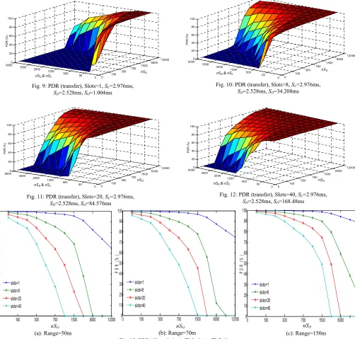
period that the nodes are obliged to refrain transmitting readings prior to completion of discovery and configuration states. TheSOduration (influenced by the number of slots) can
worsen the case for low durations as indicated in Fig. 9 to Fig. 12, which show a varying number of slots. The important feedback here is determining the ratio of discovery and configuration to online superframes ((nSC+ nSD)/nSO).
Accordingly, to achieve a PDR no less than 98%, for slots
(macLLDNnumUplinkTS) =1, 8, 20 and 40, then the ratio of
the number of discovery and configuration to online superframes must be no larger than 0.08, 0.2, 0.33 and 1 respectively (nSC&nSDfixed to 50). Here the ratio corresponds
to the number of online superframe to one discovery and one configuration superframe.
The second parameter is PDRdissociation which is affected by
the number and interval of dissociations periods from the network. The PDRdissociation is basically dependent on the
[image:12.612.52.290.55.427.2]transmission range and node mobility metric. Fig. 13 shows the impact of increasing the transmission range from 50m to 150m on the PDR. In this scenario, the impact of thenSOhas
the inverse affect to its impact on the PDRtransferin the case of
transfer. Here, by increasing thenSO, we are also maximizing
SCBand hence, increasing the dissociation time which will
reduce the PDRdissociation. Unlike in PDRtransfercase, here we are
looking for lownSOto ensure high PDRdissociation. In addition to
the nSOvalue, the number of slots per superframe influences
the PDRdissociation, where for few slots, better PDRdissociationcan
be achieved. This is traced to the impact ofSOon bothSCBand
Dis that also maximizes dissociation time and in turn minimizes PDRdissociation. Although the associatedASTphase is
deterministic, the remaining mobile node’s lifecycle phases
(SCB, ASTreqandDis) are stochastic and thus, the impact will
vary depending on the node’s mobility metric.
According to Fig. 9 to Fig 13, we can deduce that both nSO
and SO have a contradicted role in
both PDRdissociation and PDRtransfer. Fig. 13(a) shows that for a
transmission range of 50m, in order to achieve a PDR no less than 90%, the maximum number ofnSOis 150. Meanwhile, for
the of case 150m, the maximumnSOvalue to gain no less than
91% PDR is 500.
In order to comprehend the advantage of the proposed MA-LLDN over MA-LLDN, Fig. 14 and 15 show how the MA-MA-LLDN gains higher PDR than LLDN with regards tonSC&nSD=50,
which is considered the best scenario for LLDN. Even while varying the number of slots or transmission range, MA-LLDN exhibits different variations. This is contributed by the dependency on theMgts inside online state to accommodate mobile node association rather than flipping to discovery and configuration states (as is the default structure of LLDN). Moreover, the flexibility of MA-LLDN to make the online Fig. 9: PDR (transfer), Slots=1,SC=2.976ms,
SD=2.528ms,SO=1.004ms
Fig. 12: PDR (transfer), Slots=40,SC=2.976ms,
[image:13.612.51.553.59.538.2]SD=2.528ms,SO=168.48ms
Fig. 10: PDR (transfer), Slots=8,SC=2.976ms,
SD=2.528ms,SO=34.208ms
Fig. 11: PDR (transfer), Slots=20,SC=2.976ms,
SD=2.528ms,SO=84.576ms
nSO
nSD& nSC
nSO
nSD& nSC
nSD& nSC nSD& nSC
nSO nSO
0 100 300 700 1500 6000 12000 0 50 500 1250 2500 3500 6000 0 20 40 60 80 100 P D R (% ) 0 100 300 700 1500 6000 12000 0 50 500 1250 2500 3500 60000 20 40 60 80 100 P D R (% ) 0 100 300 700 1500 6000 12000 0 50 500 1250 2500 3500 60000 20 40 60 80 100 P D R (% ) 0 100 300 700 1500 6000 12000 0 50 500 1250 2500 3500 60000 20 40 60 80 100 P D R (% ) (c): Range=150m (b): Range=70m (a): Range=50m
Fig. 13: PDR (dissociation), [s]=6m/s, [d]=9m, [P]=6s,nSC&nSD=50SC=2.976ms,SD=2.528ms,
nSO nSO nSO
0 100 300 700 1500 6000 12000
0 10 20 30 40 50 60 70 80 90 100 P D R (% ) slots=1 slots=8 slots=20 slots=40
0 100 300 700 1500 6000 12000
0 10 20 30 40 50 60 70 80 90 100 P D R (% ) slots=1 slots=8 slots=20 slots=40
0 100 300 700 1500 6000 12000
state accept associations, led to ignore the impact ofnSC&nSD
on the dissociation issue.
In the meantime, to highlight the differences between MA-LLDN and MA-LLDN in term of dissociation time, Fig. 16 depicts how the MA-LLDN manages to obtain low dissociation time whilenSC&nSD&nSO=50. At these settings, the LLDN has
its low dissociation time (increasing these parameters will maximize the dissociation time). The most influential factor to the dissociating time is theSCBtime which is depicted in Fig
17. TheSCBis mainly affected bySOvalue which is raised by
increasing the number of slots in each superframe. The demonstrated dissociation time here represents the expected time that a node will be disconnected from a network once it has left a POS.
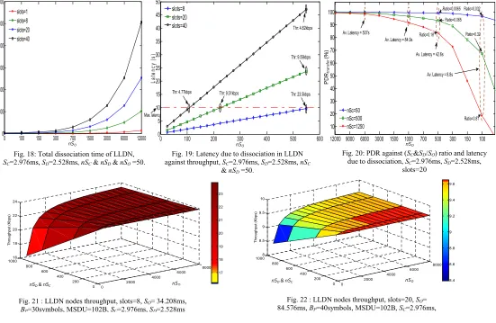
Fig. 18 describes the expected dissociated time with respect to the number of slots and nSO. It identifies a real problem
with LLDN that violates the target of low latency. It’s clear that for large nSO values the latency can be over 800s.
Accordingly, to meet the required target of LLDN for
macLLDNnumUplinkTS=20 and a latency less than 10s, the
maximumnSO can be no greater than 200 as in Fig. 19. The
realized PDRassociationbased on nSO=200 could be about 87%
for 50m range and 95% for 150m range. In addition, the maximum PDRtransfer that can be ascertained based on these
settings is 74%.
Fig. 19 shows the impact of latency incurred by dissociation versus throughput. The disadvantage at this point is that increasing nSO here will raise rapidly the latency due to
increasing the dissociation time, but in turn it has no noticeable advantage on the achieved throughput.
Finally, Fig. 20 demonstrates the relation between the PDRtransfer and the encountered average latency plus the ratio
ofSD,SC over SO. Seeking to reduce the latency (caused by
dissociation) and to achieve higher connectivity intervals, the
nSOvalue must be reduced againstnSCandnSD(increasing the
SO toSD & SC ratio). In turn, the PFRtransfer is unfortunately
dropping to its lowest rates of 20% and 68% for 0.81 and 0.32 ratios respectively (fixingnSO at 100). For lownSC value as
50, the PDRtransferis rarely impacted and keeps a steady low
degradation against decreasing nSO. In summary, Fig. 20
shows the overhead of maintaining low latency on the PDRtransferof the associated nodes to the network.
Fig. 21 to 23 give us a snapshot regarding the LLDN node’s throughput. The case of slots=1(i.e. just a single node exists) has not included here, but in general the average throughput to meet a dissociation of no more than 10ms is 165kbps. Fig. 21 (for slots=8) clearly shows an advantage over slots=20 and 40 since the SO is being maximized with each slot number
increase. In order to gain a dissociation less than 10ms, for the case of slots=8 andnSC&nSD=50, the average throughput is
23.5kbps. For the case of 20 nodes and nSC & nSD=50, the
throughput has been declined to 9.5kbps while it has been degraded further for case of 40 nodes to be only 4.7kbps. Hence, the throughput metric must be carefully considered in order to meet the target constrains of LL applications. Regarding our analysis, we have ignored the transmission failure impact caused by packet collisions due to the fact that we assume the nodes are running with a tight synchronization that can cancel any probability of collision.
VII. CONCLUSION
[image:14.612.59.513.51.329.2]The objective of the IEEE 802.15.4e LLDN operation mode is to provide a deterministic network behavior for several application types and especially the industrial ones that require Fig. 14 : Comparison between the PDR of both LLDN and
MA-LLDN, slots=8,SO=34.208ms,SC=2.976ms,SD=2.528ms,nSC
=50.
[image:14.612.298.557.55.333.2]Fig. 15: Comparison between the PDR of both LLDN and MA-LLDN, slots=20,SO= 84.576ms,SC=2.976ms,SD=2.528ms,nSC=50.
Fig. 16: Comparison between LLDN and MA-LLDN dissociation time,SC=2.976ms,SD=2.528ms,nSC&nSD&nSO=50.
Fig. 17: Delay of scanning for beacon,SC=2.976ms,
SD=2.528ms,nSC&nSD&nSO=50.
50m 70m 150
60 65 70 75 80 85 90 95 100
Transmission range (m)
P
D
R
(%
)
MA-LLDN LLDN, nSo= 50 LLDN, nSo=150 LLDN, nSo=700
50m 70m 150m
60 65 70 75 80 85 90 95 100
Transmission range (m)
P
D
R
(%
)
MA-LLDN LLDN, nSo=50 LLDN, nSo=150 LLDN, nSo=700
8 20 40
0 1 2 3 4 5 6
Number of Slots
D
is
s
o
c
ia
ti
o
n
T
im
e
(s
)
LLDN MA-LLDN
8 20 40
0 0.5 1 1.5 2 2.5 3 3.5 4 4.5
Number of Slots per Superframe
S
c
a
n
n
in
g
T
im
e
(s
)
[image:14.612.54.294.60.324.2] [image:14.612.311.541.194.325.2]low latency. The determinant fact regarding several LL applications is the existence of mobile nodes, by which the default communication stack must be able to operate efficiently. Unfortunately, the default IEEE 802.15.4e LLDN infrastructure suffers with the existence of mobile nodes. Accordingly, the objective of providing deterministic and LL services has been violated. In this paper we have provided a comprehensive analysis to the impact of node mobility upon the LLDN while presenting a feasible approach to tackle the overhead of node movement. Even with a static scenario, the assumption of collecting sensor readings of 20 sensor nodes in less than 10ms is not valid unless we have no more than one byte payload, as in (3).
The major flow in the LLDN design that degrades the performance during the node movement is the classification of the network transmission status. Dividing the transmission states into three events (discovery, configuration and online) affects negatively both dissociated and associated nodes. The orphan nodes that seek to join the network are relying on both discovery and configuration transmission states to determine the network and synchronize with the coordinator. Hence, the node connectivity factor is dependent on the occurrence ratio of these two states to the duration of online states during a network lifetime. In the meantime, the throughput of the connected nodes is dependent on the interval of the online states since during the discovery and configuration states the nodes are forbidden from sending readings. Accordingly, there must be a tradeoff between thenSOvalue and the value ofnSD
andnSC to realize an acceptable amount of throughput versus
dissociation time. Increasing thenSO to the value ofnSDand
nSC will maximize node throughput, but in turn increase the
dissociation time.
In addition to the impact of the transmission states, the mobility metric, transmission range and superframe duration (determined by the number of slots) also influence the LLDN network functionality.
[image:15.612.31.582.54.413.2]The proposed MA-LLDN model manages to reduce the dissociation time to be less than the duration of two online superframe durations. MA-LLDN reduces the dissociation delay in different scenarios by a factor of 75%. In addition, the Fig. 21 : LLDN nodes throughput, slots=8,SO= 34.208ms,
BP=30symbols, MSDU=102B,SC=2.976ms,SD=2.528ms
Fig. 22 : LLDN nodes throughput, slots=20,SO=
84.576ms,BP=40symbols, MSDU=102B,SC=2.976ms,
S =2.528ms
Fig. 23 : LLDN nodes throughput, slots=40,SO= 168.48ms,
BP=80symbols, MSDU=102B,SC=2.976ms,SD=2.528ms
nSO
nSD& nSC
nSD& nSC
nSD& nSC nSO
nSO 0 2000 4000 6000 8000 0 200 400 600 800 100016 18 20 22 24 T h ro u g h p u t (K b p s ) 17 18 19 20 21 22 23 0 2000 4000 6000 8000 0 200 400 600 800 10008 8.5 9 9.5 10 T h ro u g h p u t (K b p s ) 8.4 8.6 8.8 9 9.2 9.4 9.6 0 2000 4000 6000 8000 0 200 400 600 800 10004.5 4.55 4.6 4.65 4.7 4.75 4.8 4.85 T h ro u g h p u t (K b p s ) 4.55 4.6 4.65 4.7 4.75 4.8
Fig. 18: Total dissociation time of LLDN,
SC=2.976ms,SD=2.528ms,nSC&nSD&nSO=50.
Fig. 19: Latency due to dissociation in LLDN against throughput,SC=2.976ms,SD=2.528ms,nSC
&nSD=50.
nSO P D Rtr a n sf e r (% ) nSO nSO
Fig. 20: PDR against (SC&SD/SO) ratio and latency
due to dissociation,SC=2.976ms,SD=2.528ms,
slots=20
0 100 150 300 700 1500 3000 6000 12000
0 200 400 600 800 1000 1200 D is s o c ia ti o n (s ) slots=1 slots=8 slots=20 slots=40
0 100 200 300 400 500 600
0 5 10 15 20 25 30 35 40 45 50 L a te n c y (s ) slots=8 slots=20
slots=40 Thr: 4.82kbps
Thr: 9.59kbps
Thr: 23.5kbps Thr: 9.51kbps
Thr: 4.77kbps
Max. latency
12000 9000 6000 3000 1500 1000 700 500 300 150 100 10 20 30 40 50 60 70 80 90 100 nSc=50 nSc=500 nSc=1250
Av. Latency = 84.9s
Av. Latency = 42.6s
Ratio=0.032
Ratio=0.81 Av. Latency = 8.8s Av. Latency = 507s Ratio=0.16 Ratio=0.32
[image:15.612.40.282.418.540.2]