ana
aerøøpmenrprc
(ve
waste
management
and
storage
Shai
■■.■:■:
Commission of the European Communities
nuclear science
and technology
The
Community's
research
and
development
programme
on
radioactive
waste
management
and
storage
Shared
cost
action
Annual
progress
report
1989
Volume
2
Published by the
COMMISSION OF THE EUROPEAN COMMUNITIES Directorate-General
Telecommunications, Information Industries and Innovation L-2920 Luxembourg
LEGAL NOTICE
Neither the Commission of the European Communities nor any person acting on behalf of the Commission is responsible for the use which might be made of the
following information
ISBN 92-826-1591-X (Volume 1) ISBN 92-826-1590-1 (Volumes 1 and 2)
Cataloguing data can be found at the end of this publication
Luxembourg: Office for Official Publications of the European Communities, 1990
ISBN 92-826-1592-8 Catalogue number: CD-NB-12761-EN-C
© ECSC-EEC-EAEC, Brussels · Luxembourg, 1990
Foreword
The Council of the Ministers of the European Communities adopted
through its decision on March 12, 1985 (1) a five year R&D programme on "Management and Storage of Radioactive Waste" for the period 1985-1989. This R&D programme is being carried out on the competent public organisations and private firms within the Member States. At the end
of 1989 over 256 contracts had been concluded with some 70 bodies
within the European Community (A3 Ζ national bodies and research
centres, 36 Ζ private industries, 21 Ζ universities and institutes). The Commission's contribution to the cost of the programme amounts to 62 million ECU (for the five year period).
In the management of the programme, the Commission is being assisted by the Management and coordination advisory committee "Nuclear fission energy - Fuel cycle/processing and storage of waste" (see for list of members pageVII, Vol.2 ) .
The launching of specific coordinated research projects within the
programme has promoted the co-operation between various teams within the Member States. Kalf of the contracts concluded are dedicated to
such projects. The exchange of fresh scientific information on the
progress and results of the work carried out in the framework of the
programme is assured at operational level by periodical progress
meetings of working groups for the various projects. The final results
of the research contracts are published in the EUR series which
publication are e.g. listed in the six monthly news letter, EC FOCUS. In addition the Commission is publishing annual progress on the overall programme. This report, covering the year 1989, is the fourth of this
type, the previous being published under no EUR 11089 for the year
1986, no EUR 11482, for the year 1987 and EUR 12141 covering the year
1988. For each contract the objectives, working programme and a
summary of progress and results obtained have been given as prepared by the contractor, under the responsibility of the project leader. The Commission wishes to express its gratitude to all scientists who have
contributed to this report. The overall results of the five year
programme will be presented, as usual, to the worldwide scientific
community at the third European Conference on Radioactive Waste
Management to be held .September 17-21, 1990 in Luxembourg.
S. ORLOWSKI
V O L U M E 2
C O N T E N T S
PART A : WASTE MANAGEMENT STUDIES AND ASSOCIATED R & D ACTIONS
Page
MEMBERS OF THE MANAGEMENT AND COORDINATION ADVISORY COMMITTEE VII
TASK 4 : RESEARCH IN SUPPORT OF THE DEVELOPMENT OF DISPOSAL FACILITIES; SHALLOW BURIAL AND GEOLOGICAL DISPOSAL
STUDIES 3
4.1. - Research relating to sites and their characterization 7
4.I.A. - General survey of geological formations and
development of measuring techniques 9
4.I.B. - Geo-forecasting studies 47
4.l.C. - Rock mechanics 51
4.2. - Repositories and engineered barriers 105
4.2.A. - Repository design and disposal techniques 106
4.2.B. - Engineered barriers 107
4.2.B.I. - HLW container development 109
4.2.B.2. - Backfilling and sealing of
radioactive waste repositories 113
4.3. Radionuclide migration in the geosphere (MIRAGE) 193
4.3.A. - Actinide and fission product geochemistry
aquifer systems 195 4.3.B. - In-situ migration experiments and development
of measuring techniques 261
4.3.C. - Natural analogues 289
4.3.D. - Development of calculation tools for the
4.4. - Shallow land burial 371
TASK 5 : SAFETY OF GEOLOGICAL DISPOSAL 383
PACOMA Project 387
Support studies 417
TASK 6 : JOINT ELABORATION OF RADIOACTIVE WASTE MANAGEMENT
POLICIES 429
PART Β : CONSTRUCTION AND/OR OPERATION OF UNDERGROUND -EXPERIMENTAL FACILITIES OPEN TO COMMUNITY JOINT
ACTIVITIES 441
The HAW Project at Asse 443
The HADES Project at Mol 457
MEMBERS OF THE MANAGEMENT AND COORDINATION ADVISORY COMMITTEE NUCLFAR FISSION ENERGY
FUEL CYCLE/PROCESSING AND STORAGE OF WASTE (1)
(during 1989)
BELGIUM
DENMARK
FRANCE
GERMANY
G. DEDEURWAERDER J.P. MIRSCHBUHLER
K. BRODERSEN T. NILSEN
J. LEFEVRE (Chairman) P. FRIGOLA
R. SCHMIDT W. BUSCH
GREECE
IRELAND
S. AMARANTOS G. KOUTZOUKOS
J. CUNNINGHAM F. TURVEY
ITALY F. MORSELLI
P. VENDITTI
LUXEMBOURG
NETHERLANDS
PORTUGAL
P. KAYSER
H. CORNELISSEN S. KOOMEN
H.J.P. CARREIRA PICP C. RAMALHO CARLOS
SPAIN
UNITED KINGDOM
COMMISSION
M. RODRIGUEZ PARRA J. APANA LONDA
S. BROWN J.T. BRITTON
S. FINZI J. VAN GEEL
P. VENET (Secretary)
P A R T A
W A S T E M A N A G E M E N T S T U D I E S A N D
A S S O C I A T E D R & D A C T I O N S
-T A S K N o 4
TASK No. 4 ; RESEARCH IN SUPPORT OF THE DEVELOPMENT OF DISPOSAL FACILI-TIES; SHALLOW LAND BURIAL AND GEOLOGICAL DISPOSAL STUDIES
A. Objective
Evaluation and modelling of the long-term behaviour of the geological barrier
Development of disposal facilities.
B. Research topics dealt with under the 1980-1984 programme
a) Work related to sites and their characterization
- General survey of geological formations and development of measuring techniques with a view to develop large scale in-situ characterization of the geological formations by direct or indirect methods
- Geoprospective studies : development of an operational method for the prospective analysis of the characteristics of geological containment
- Rock mechanics studies.
b) Work related to geological repositories and barriers
- Improvement of the designs and technologies required for the setting up of repositories in geological formations (salt, granite, clay)
- Development of long-lived containers for vitrified waste and of methods for the backfilling sealing of openings in geological repositories.
c) Work on radionuclide migration in the geosphere
- The work mainly comprised integral experiments on migration simulation, laboratory studies concerning the properties of materials from specific sites, hydrogeologicai investigations, research on natural geological migration systems and the role of micro-organisms, and, finally, the development of calculation
tools and the intercotnparison of codes regarding transport and geochemistry.
d) Shallow land burial
1985-1989 programme
The work is mainly a continuation of the research started during the 1980-1984 programme; however, special emphasis is being put on calculation tools and their intercomparison, on investigations
attached to specific sites as opposed to laboratory work of
general nature, on the role of colloids and complexes in
radionuclide migration, on studies of natural analogues, and on the development and assessment of various backfilling materials and concepts.
Coordination is ensured by a structure of projects or working
groups :
COSA
COMPAS
Β & S
MIRAGE
COCO
CHEMVAL
NAWG
Comparison of Rock Mechanics Codes for Salt
Container Mechanical Performance Assessment
Backfilling and Sealing
Migration of Radionuclides in the Geosphere
Colloids and Complexes
Geochemical Benchmark for Mirage
Natural Analogue Working Group
D. Programme implementation
The available information on the contracts signed is listed
hereafter.
4.1 RESEARCH RELATING TO SITES AND THEIR CHARACTERIZATION
Α.I.A. General survey of geological formations and development of measuring techniques
9-The 600 m borehole project:
"Development of a surveillance method during dry-drilling of a 6OO m deep borehole in salt and performance of
geotechnical measurements in the 6OO m hole"
Contractor : Netherlands Energy Research Foundation (ECN) Petten, The Netherlands
Contract No. : FI-1W/0084
Working Period: August I986 - December 1990 Project Leader: J.R. van Seuren
A. OBJECTIVES AND SCOPE
The experiments performed in the Asse II salt mine in the FRG under the contract with the CEC during the previous programme (I98O -1984) were carried out in a drilled hole of 30 cm in diameter and 3OO m in depth; since then a dry drilling technique was developed for larger diameter holes and greater depths. In this project this technique will be tested by drilling a borehole with a diameter of 60 cm, typical for a disposal hole, and a depth of 6OO m.
An alternative for the reconnaissance drilling which takes place before the actual drilling, will be developed with GSF.
The free convergence measurements of the salt as a function of depth of the hole, will be carried out. At the bottom of the hole
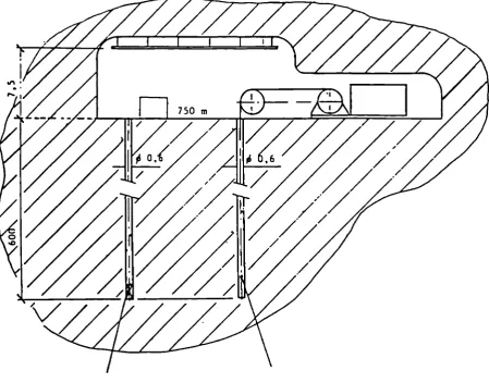
convergence measurements with variable back pressure (isothermal lithostatic measurements) will be performed. Because of the
complexity of the total construction the measurements will be done in two boreholes (Figure 1). All these results will be used for the validation of analytical techniques and computer codes.
B. WORK PROGRAMME
B.l Drilling of the borehole. B.2 Surveillance method.
B.3.I Isothermal convergence measurements.
B.3.2 Isothermal lithostatic pressure measurement.
C. PROGRESS OF WORK AND OBTAINED RESULTS
Drilling of the borehole
Although not in the contract with the CEC, the drilling of the 6OO m holes with a diameter of 60 cm is a vital part of the
experiment. This drilling is carried out by GSF (Gesellschaft für Strahlen- und UmweltForschung) under contract with BMFT.
The drilling has resulted in the following: 1. A borehole with a depth of 101,5 0. 2. A borehole with a depth of 300,5 m. 3. A borehole with a depth of 3^7,4 m.
The drilling of hole 1 and 2 will not continue. The drilling of hole 3 is temporarily stopped. The drilling rig needs major modifications and repair. It is expected that in 1990 the drilling of hole 3 can continue.
It was decided to use the second hole for convergence measurements first and later, when the lithostatic pressure measurement device was designed and tested, use this hole for those measurements. This forced change in measuring strategy, which means measurements in a not optimal drilled 300 m hole instead of in an expected straight 600 m hole, resulted in extra effort.
The hole had to be measured for straightness and the lithostatic pressure measurement device has to be surrounded by cement at the 300 m level in order to make experiments possible.
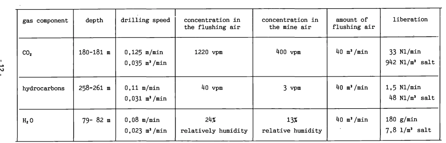
Surveillance method
The design of the system has been described in the previous reports. With this system the flushing air during drilling of
borehole 3 has been analyzed. The results are summarized in table 1.
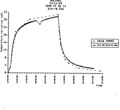
Isothermal convergence measurement
These measurements at the 300 m level in the second borehole have been started in November I988. The free convergence at this depths is a relatively slow process. It has been calculated for a depth of 3OO m and is shown in Figure 2 as part of an experimental program. It can be seen that the maximum displacement to be expected for a wall with an age of about 1 year is about 2 mm for a i year period. For a drilled hole with the same conditions this means double the amount. The hole diameter will therefore be decreased with about 4 mm.
A data report with experimental results will be available in 1990. The free convergence will in addition be measured at 200 m and 100 m
in the 3OO m hole. The unit which will measure this is in its testing fase and will be installed in the beginning of 1990.
Lithostatic pressure measurement
The design of the measuring construction has been finalized together with the pressure control station.
The design consists of a flexible rubber balloon in the form of a torus, surrounded by a rubber skirt. The torus is supported by a steel structure.
This construction has to be lowered, in the 300 m borehole, to the bottom location. To make measurements possible, it has to be
surrounded by salt cement, which has to be poured from the 750 m floor. This is done via tubing, which is lowered, together with the construction, to 300 m level.
An amount of about 2 m' cement will, by gravitation, be transported in liquid form. It has a cure time of about 24 hours and will then act as an intermediate between the rubber and the salt wall, thereby assuring that measurement can start immediately.
Table 1. Maximum values of the gas content in the flushing area of borehole 109/750/89
ro
gas component
C02
hydrocarbons
H20
depth
180-181 m
258-26I m
79- 82 m
drilling speed
0,125 m/min 0,035 m3/min
0,11 m/min 0,031 m3/min
0,08 m/min 0,023 m3/min
concentration in the flushing air
1220 vpm
40 vpm
2k%
relatively humidity
concentration in the mine air
400 vpm
3 vpm
13%
relative humidity
amount of flushing air
40 m3/min
40 m3/min
Ίθ ι3/min
liberation
33 Nl/min
942 Nl/m3 sait
1,5 Nl/min
48 Nl/m3 sait
180 g/min
DYNAMIC ISOTHERMAL LITHOSTATIC
[image:23.595.74.524.129.481.2]PRESSURE MEASUREMENT FREE CONVERGENCE MEASUREMENT OVER THE LENGTH OF THE HOLE
s
α) ß cu υ
Ή,
co
LEGEND
-a Resulting displacement [ ECN ] Resulting displacement [ BGR] -Δ Resulting displacement [EMP ]
I I I I
182.5 547.5 912.5 1095 1277.5
-*·
Time
[
days
]
Fig. 2 .Displacement of a saltwall in a 300 m deep borehole.
24
S.
* 20 ν σ> c σ"δ
S 3 tn ff)ι
ν c ο 0) Ε 18 16· 14 12 10 8 6 42
+
IECNice^i**!
Ι
Ι
>
ι
ι
ι
ι
ι
ι
Γ
LEGEND
β ·>Resultine » ΔResultine
ι I
I IPressurechange [ ECN]
IPressurechange [ BGR] IPressure change[ EMP]
I
Ι
ι ι
ι ι
ι ι
"' ^*""
lj&*
ι .'
ι / s-Z>^
1
1
ι— L Γ1
547.5 730 912.5 1095
*· Time [days ]
1277.5
547.5 730 912.5
F i g .
1095
►■ Time [ days]
3. Experimental program with the lithographic pressure measurement station in a 300m deep borehole.
Faults in clays: their detection and properties
Contractor: BGS, Keyworth, Nottingham, UK
Contract No.: FI1W/0085/UK
Contract Period: October 1986-October 1989
Project Leaden M.A.Brightman
A. Objectives and Scope
Faults occur in most mixed sedimentary environments but their effects on regional
groundwater flow patterns are poorly understood. The hydrogeologicai significance of
faulted clay layers is of particular relevance where mudrocks are potential host formations
for radioactive waste repositories.
In cooperation with ISMES of Italy two faults through clay layers will be studied
(one site in the UK and one in Italy). The project has three objectives
:-1. To develop suitable geophysical techniques to detect water bearing faults in clays. These
techniques will aim to differentiate between hydraulically active faults and those which are
either sealed or non-water bearing.
2. To measure the hydrogeological properties of faults in sequences of mudrocks and
aquifers. This will be achieved by measuring the hydraulic and chemical properties of the
fault directly and by measuring the effect of the fault on the underlying aquifers.
3. To define suitable techniques for use in site investigations and methods for assimilating
faulted boundaries into flow and transport models in clays and mixed sediments.
B. Work Programme
B.l. Desk study to evaluate a number of potential UK study sites; selection of two
preliminary sites.
B.2. Initial geological and geophysical investigations of the preliminary UK sites; selection
of the final study site.
B.3. Development of geophysical techniques for fault identification.
B.4. Detailed geophysical survey of the study site.
B.5. Borehole drilling.
B.6. Wireline geophysical logging of the boreholes.
B.7. Hydrogeological testing of the boreholes.
B.8. Synthesis of the results to evaluate the significance of the fault.
-C.
Progress
of
work
and
obtained
results
State
of
advance
Seismic
cross-hole
tomographic
surveys
of
the
fault
have
been
completed.
Hydrogeologie
al
testing
and
groundwater
sampling
have
been
completed.
Data
interpretation
and
reporting
have
been
completed.
B.3.,B.4.,B.7.
and
B.8.
have
been
completed.
Progress
and
results
1.
Detailed
geophysical
characterisation
of
the
fault
zone
(Β.3..Β.4Λ
Cross-hole
seismic
tomography
surveys
have
been
completed
in
the
borehole
array
at
Down
Ampney
(Jackson
et
al,
1989b)
with
the
twin
aims
of
imaging
the
fault
plane
to
examine
its
geological
structure,
and
to
determine
changes
in
physical
properties
of
the
clay
caused
by
the
faulting.
The
measurement
borehole
array
was
designed
to
allow
both
the
gross
lithological
changes
on
the
upthrown
side,
and
the
fault
zone
within
the
clay
on
the
downthrown
side,
to
be
investigated
by
the
cross-hole
seismics.
The
environment
at
Down
Ampney
was
favourable
for
cross-borehole
transmission
seismic
tomography,
with
no
background
noise,
and
very
low
attenuation
of
the
seismic
waves.
A
high
resolution
borehole
seismic
source
and
a
multi
element
hydrophone
array
was
used
for
the
surveys.
This
propagated
energy
of
1.5m
wavelength
in
the
Oxford
Clay,
representing
a
frequency
of
1.2KHz
which
is
far
higher
than
that
used
in
standard
site
investigation
practice.
The
noise
levels
were
low
enough
to
enable
whole
waveforms
to
be
acquired
which
often
exhibited
both
reflections
and
refractions
from
the
thin
Cornbrash
layer,
indicating
the
benefits
of
underground
seismic
surveys
that
are
not
degraded
by
thin
attenuating
surface
layers.
The
effects
on
the
velocity
re-construction
of
using
different
arrivals
were
studied,
and
the
removal
of
those
events
which
were
critically
refracted
along
the
Cornbrash
improved
the
velocity
inversion.
Even
though
the
geological
setting
was
very
favourable,
it
was
concluded
that
the
simplest
straight
ray
interpretation
procedure
produced
the
best
results
with
the
real
field
data.
The
finite
wavelength
and
the
uncertainty
in
the
exact
position
and
shape
of
the
refracting
zones
affected
by
the
fault
reduced
the
benefits
of
bent
ray
modelling.
This
is
an
unusual
situation
as
the
majority
of
reported
case
histories
show
that
bent
ray
modelling
produces
results
that
identify
geological
structures
more
clearly.
The
results
from
Down
Ampney
show
a
zone
of
5%
lower
velocity
within
the
clay
coincident
with
the
fault
zone
observed
by
the
geological
logging
of
the
core.
This
lower
a
higher
porosity
and
lower
strength.
This
implies
that
the
hydraulic
conductivity
of
the
fault
zone
is
likely
to
be
greater
than
the
surrounding
clay.
Furthermore
the
reconnaissance
resistivity
surveys
showed
fault
responses
thought
to
be
due
to
altered
zones
within
the
clay,
that
were
of
far
greater
magnitude
than
at
the
site
of
the
borehole
array.
This
may
suggest
that
the
fault
zone
detected
by
the
seismic
tomography
is
atypical
of
the
Down
Ampney
site
on
a
larger
scale,
and
that
the
changes
in
physical
properties
may
be
greater
in
other
parts
of
the
fault
2.
Hydrogeological
and
hydrochemical
characterisation
(Β.7Λ
Groundwater
heads
and
hydraulic
conductivities
have
been
measured
at
Down
Ampney
to
investigate
the
local
groundwater
flow
regime
and
are
listed
in
Table
1.
The
array
of
measurement
boreholes
was
designed
to
provide
three
vertical
profiles
of
groundwater
head,
one
through
the
upthrow
side,
one
through
the
downthrow
side
and
one
through
the
fault
zone.
The
groundwater
levels
measured
in
the
boreholes
with
screened
sections
through
the
Great
Oolite
and
the
Cornbrash,
on
both
sides
of
the
fault,
were
lower
than
had
been
expected,
being
depressed
by
groundwater
abstraction
for
public
water
supply
by
two
pumping
stations
a
few
kilometres
distant.
The
groundwater
heads
measured
in
the
piezometers
did
not
show
any
consistent
trends
supporting
either
upward
or
downward
.
groundwater
flow.
The
most
likely
explanation
seemed
to
be
that
the
groundwater
heads
in
the
low
hydraulic
conductivity
had
not
reached
equilibrium
with
the
heads
in
the
aquifer
which
were
generated
by
relatively
recent
pumping
effects.
This
hypothesis
to
explain
the
head
distribution
was
tested
by
mathematical
modelling
using
values
of
the
hydraulic
conductivities
and
storativities
measured
at
the
site.
A
2-D
vertical
section
about
2km
long
and
100m
deep
was
modelled
using
the
finite
element
code
FEMWATER.
The
clay
and
other
impermeable
layers
were
assigned
conductivities
in
the
range
ÏO^-IO
1 1ms
-1and
the
limestone
layers
IO
-5—10
-6ms
-1.
The
fault
elements
were
given
various
properties
in
order
to
simulate
the
measured
head
pattern.
The
top
surface
at
ground
level
was
given
a
fixed
head
boundary
condition
of
0m
and
the
lower
surface
was
taken
to
be
a
no-flow
boundary.
The
boundary
conditions
at
each
end
of
the
model
were
altered
for
various
simulations.
The
water
abstraction
history
was
modelled
as
a
simple
step
drawdown
from
heads
of
+10m
in
the
White
Limestone
to
the
present
-11m
around
30
years
ago.
This
simplification
was
as
accurate
as
was
justified
by
the
available
data.
A
number
of
simulations
showed
that
the
measured
heads
were
consistent
with
this
model
if
the
fault
was
assigned
a
low
conductivity
of
approximately
10
10ms
1except
between
the
downthrown
Cornb"ish
and
upthrown
White
Limestone
where
it
was
given
an
intermediate
value
of
10~
8ms
-1.
18-Depth
(m
below
gl)
14.1-16.2
28.2-30.3
32.1-37.0
48.9-85.0
Depth
(m
below
gl)
14.3-16.3
22.7-25.2
28.8-30.8
42.2-44.9
Depth
(m
below
gl)
23.0-25.1
49.0-51.4
67.6-69.9
82.8-88.1
Formation
Oxford
Clay
Kellaways
Combrash
Great
Oolite
Formation
Fault
zone
Fault
zone
Fault
zone
Fault
zone
Formation
Oxford
Clay
Oxford
Clay
Kellaways
Combrash
Upthrow
side
Groundwater
head
(m
above
gl)
-0.2
1.7
-6.0
-11.0
Fault
zone
Groundwater
head
(m
above
gl)
4.9
3.0
0.8
-1.53
Downthrow
side
Groundwater
head
(m
above
gl)
3.5
5.2
2.4
-10.0
Hydraulic
conductivity
(ms-
1)
9xl0-
n9xl0-
12lxlO-
55x10-5
Hydraulic
conductivity
(ms-
1)
2xl0-
102xl0-
84x1ο-
11
Hydraulic
conductivity
(ms-
1)
4xl0"
126xl0"
123X10-
114x1ο-6
Table
1
Groundwater
heads
and
hydraulic
conductivities
measured
at
the
Down
Ampney
Fault
Research
Site.
Hydraulic
conductivity
was
measured
in
the
aquifer
units
by
constant
rate
abstraction
pumping
tests
and
in
the
clays
by
pulse
tests.
The
results
show
that
the
hydraulic
conductivity
of
the
fault
zone
tends
to
be
between
one
and
two
orders
of
magnitude
greater
than
the
adjacent
unfaulted
clay.
Pore
water
has
been
squeezed
from
clay
core
samples
and
groundwater
samples
have
been
collected
during
pumping
tests
and
from
piezometers.
These
samples
have
been
analysed
for
major
elements
and
stable
isotope
compositions
and
profiles
of
variations
in
pore
water
and
groundwater
chemistry
on
both
sides
of
the
fault
and
through
the
fault
itself
have
been
constructed.
These
profiles
suggest
that
the
fault
has
had
a
significant
effect
on
3.
Evaluation
of
the
fault
(B.8.)
The
following
technical
reports
have
been
produced
to
evaluate
the
significance
of
the
fault
:
HI
Alexander,
J.
1989.
Faulting
in
mudrocks
:
the
selection
of
potential
research
sites.
Report
of
the
British
Geological
Survey
WE/89/12
HI
Brightman,
M.A.,
Hallam,
J.R.
and
Ambrose,
K.
1989a.
The
boreholes
and
geology
of
the
Down
Ampney
Fault
Research
Site.
Report
of
the
British
Geological
Survey
WE/89/
(in
press)
131
Brightman,
M.A.,
Abbott,
M.A.W.
and
Sen
M.A.
1989b.
Hydrogeologicai
investigation
of
the
Down
Ampney
Fault
Research
Site.
Report
of
the
British
Geological
Survey
WE/89/
(in
press)
IM
Hallam,
J.R.,
Jackson,
P.D.,
Raines,
M.G.,
and
Rainsbury,
M.P.
1989.
High
resolution
resitivity
measurements
at
the
Down
Ampney
Fault
Research
Site.
Report
of
the
British
Geological
Survey
WE/89/
(in
press)
151
Horton,
Α.,
Ambrose,
Κ.,
and
Cox,
B.M.
1989.
Geological
sequence
at
the
Down
Ampney
Fault
Research
Site,
Gloucestershire,
England.
Report
of
the
British
Geological
Survey
WE/89/7
161
Jackson,
P.D.,
Hallam,
J.R.,
Raines,
M.G.,
Rainsbury,
M.P.,
Greenwood,
P.G.,
and
Busby
J.P.
1989a.
Reconnaissance
geophysics
to
locate
major
faults
in
clays.
Report
of
the
British
Geological
Survey
WE/89/32
ΠΙ
Jackson,
P.D.,
Greenwood,
P.G,
Raines,
M.G.,
Rainsbury,
M.P.,
and
Hallam,
J.R.
1989b.
Seismic
tomography
investigation
of
the
Down
Ampney
Fault
Research
Site.
Report
of
the
British
Geological
Survey
WE/89/
(in
press)
/8/
Raines
M.G.,
Jackson,
P.D.,
Evans,
C.J.,
Meldrum,
P.,
and
Rainsbury,
M.
1989.
An
evaluation
of
the
anisotropy
of
the
clays
of
the
Down
Ampney
Fault
Research
Site.
Report
of
the
British
Geological
Survey
WE/89/48
191
Ross,
C.A.M.
1989
The
chemistry
of
the
clay
pore
fluids
at
the
Down
Ampney
Fault
Research
Site.
Report
of
the
British
Geological
Survey
WE/89/
(in
prep)
HOI
Sen
M.A.
1989.
Hydrogeological
modelling
of
the
Down
Ampney
Fault
Research
Site.
Report
of
the
British
Geological
Survey
WE/89/
(in
prep)
METHODOLOGY FOR APPLICATION OF ELECTRIC AND ELECTROMAGNETIC BOREHOLE TECHNIQUES FOR DETAILED EXPLORATION OF FRACTURED ROCKS
Contractor; BRGM, Geophisics Dpt., ORLEANS (F) Contract No; FI1W/0086
Duration of contract; July 1986 - June 1989 Period covered; January 1989 - June 1989 Project leader; G. Pottecher, P. Valla
Title : DEVELOPMENT OF A SELF-CONTAINED DRILL-HOLE CHROMATOGRAPHIC PROBE
Contractor : CEA - CEN CADARACHE F
13108 - Saint Paul lez Durance
Contract n# : FI1W/0087
Working period : November '86 - November '89
Project Leader : J.M. Vinson
A. OBJECTIVES AND SCOPES
The study of the transuranlan nuclide migration from radio-active waste storage places is based on the knowledge of the natural environment and, in particular, of the chemical composition of the water : the transfer vector.
In addition to major elements, the water also contains trace elements which play a prominent part not only on the general equilibrium, but
also on the radionuclide migration possibility.
This is in particular the case of the Lanthanides, present in the granitic and argillaceous environments, whose role of sorption competitors with respect to the Actinides has been exhibited throughout numerous experiments.
The scope of this contract is to manufacture and operate a chromatographic probe to be used in a deep drill-hole, so designed as to acquire a representative sample under conditions of equilibrium of the natural environment, to preconcentrate it by elimination of the saline content and to store it for ulterior analysis at the surface.
B. WORK PROGRAM
B.l Process Development
B.l.l Principle laying-down and delineation. In laboratory model.
B.l.2 Definition of final probe design after study on model. Realization and adjustment on CADARACHE site.
B.2 Probe Qualification In the Deep Drill-hole of AÜRIAT
B.3 Application to 3 reference sites
22-C. WORK PROGRESS AND RESULTS OBTAINED
Summary
The analysis of AURIAT samples shows that the very low level of the lanthanldes concentrations -I.e. 1 ppb- so another technic, ICP/MS, has been tested.
The probe Is now manufactured and has been qualified on AURIAT site. The study of AURIAT deep bore-hole Is undergoing.
Some anionic columns are also used to study anionic species In the bore-hole water.
C.l Progress and results
C.l.l Analytical studies
A lot of tests driven with several analytical methods show the difficulties of working at very low concentration level.
The observed AURIAT water concentrations are about 10 ppb for Ce,
1 ppb for La and lower for other lanthanldes (10 to 10"z ppb).
These concentrations do not allow a reliable analysis classical spectrophotometry after chromatographic separation. They make the use of the most achieved methods necessary. ICP/MS technic needs more development but could be the most interesting in correlation with the neutronic activation, heavier but more accurate.
Varied kind of stresses limit the analytical abilities. They are : saline charge, reconcentration and more generally all operations intended to surface separations. The probe target is the limitation of stresses by on-line saline charge elution and in situ studied species concentration.
The realisation of an acidic buffer medium of pH2 appeared to allow both elimination of monovalent cations and better concentration of
lanthanldes.
C.l.2 Manufacture and development of the equipment
During this year, all the tool manufacturing has been realised. The logistical support and the electronical surface device have been defined and built.
All workshop tests have been made even with drastic thermal conditions in order to check good making and durability of mechanical, electrical and electronical components.
C.2 Qualification on AÜRIAT site
C.2.1 The probe
Site experimentations have been realised in order to check the ability of the probe in bore-hole with hydrostatic pressure and 2000 m of wire-line.
Some defects depending of length of imersed wire-line appeared and were corrected. After some 6 tests the probe was able to work correctly.
C.2.2 Experimental process
During these experiences, the analytical methods were tested. The concentration factor has to be adjusted in order to avoid acidic impurities effect even for suprapure acid, because of lanthanide occurence in it at the same level than in water.
This disturbance occurs especially when lanthanides are carried away from columns by concentrated acid for analysis.
The procedure depends of the level of the elements the pH is adjusted
at 2 by alternative sequences of 90 X water and 10 X nitric acid
0.1 N. 100 or 200 ml of water are percolated for Ce and La analysis. Volume of 1 to 2.5 1 are needed for other lanthanides with a concentration factor of 200 to 500.
Fracture mapping in clays
Contractor: University of Exeter, Exeter, UK. Contract No: FI1W/0088
Duration of Contract:September I986 - August I989 Period covered: January I989 - August I989 Project Leader: Dr. E.M. Durrance
A. OBJECTIVES AND SCOPE
If faults occur in the rock mass surrounding a nuclear waste
repository, there is a risk that the return of hazardous radionuclides to the biosphere will take place by migration along these zones of higher permeability. However, the detection and characterisation of faults is difficult, especially in soft rocks such as clay, and little development of techniques has taken place. The objective of this programme is to develop techniques that will be suitable for routine use in both the preliminary and detailed stages of site investigation. The approach used is based on the observation that faults act as zones of preferential migration in the natural degassing of the Earth. Soil gas exploration methods are applied to detect zones of anomalous gas geochemistry. The procedure followed is based upon samples obtained from a depth of about 0.5m along a series of traverse lines. Once a fault has been located, spiking of the high permeability zone from a borehole drilled to intersect the fault plane, will take place with specific gases of different
compositions. The ground will then be resurveyed to determine the
migration characteristics of the gas within the fault. Test sites in the UK and Italy are to be investigated in co-operation with BGS (Keyworth) and ISMES (Rome). BGS and ISMES are responsible for site selection and the drilling programme, but some trials will be conducted at sites near Exeter.
B. WORK PROGRAMME
B.l. Equipment development. B.2. Site selection
B.3· Soil gas geochemistry ^ 2-n 222
B.3.1. Reconnaissance soil gas surveys measuring He, Rn, Rn, 0_ C0_ and some organic gases.
B.3.2. Detailed soil gas surveys of anomalous zones identified in the reconnaissance surveys.
B.3.3. Spiking of vertical boreholes and resurvey of soil gases.
B^·1*· Spiking of inclined boreholes and resurvey of soil gases.
C. PROGRESS OF WORK AND OBTAINED RESULTS
The main experiment on gas flux through faulted clay ground was
conducted at Down Ampney, Gloucestershire (UK),using a gas injection
techniques via a borehole. Enhanced concentrations of the injected gases
(CO2 and He) were successfully detected later in the soil around the bore
hole. A second visit was made to the Narni site in Italy for a more
detailed soil gas survey over the suspected extension of a fault in the
adjacent quarry, this time including Rn with C02,02 and He measurements.
The contract ended on 31 August 1989· A final report has been
produced summarising the results from the threeyears' work.
Soil gas geochemistry (B.3.2.)
A fiveday programme of soil gas surveying at the clay quarry site at
Narni (Italy) enabled 85 sample points to be sampled and analysed for CO2,
O2, He and Rn. A tenmetre sample spacing was used on three parallel
traverses (10m apart) along each of two traverse lines at 028° and 053°
directions from north. These 120m long lines were those used by ISMES
(Roma) for geophysical measurements. The use of three parallel sets of
readings enabled radial averaging techniques to be applied to the results,
to eliminate random spurious values. Overall statistics for each gas
analysed show lognormal distributions for Rn and CO2, making them
potentially more useful for fraction detection than He which showed low
anomalies and a normal distribution. The two main anomalies detected,one
on each traverse line, suggest a 180° trend of a major fracture.
Consideration of all peaks above background, however, suggests linkage
along a parallel series of lineations at a 125° trend. Intersection of
both trends may be the most likely explanation of the highest anomalies.
Spiking of boreholes (Β·3·3·)
A borehole (No. 10) was made available for gas injection work by BGS
at the Down Ampney (UK) site. This vertical borehole is located just
north of the outcrop of the northerly dipping normal fault plane in Oxford
Clay. Gas was introduced to the Cornbrash aquifer horizon at a point
close to the fault, upward passage of gas being prevented by the clay
above and a rubber packer inflated in the borehole at the base of the clay.
Gases reaching the surface via the fault, a distance of about 35m, were
sampled by means of soil probes.
For CO2, probe sites were position along and to either side of the
fault outcrop 12.5m apart in the form of a grid. For He more closely
spaced sites on a traverse orthogonal to the fault was adopted. This was
necessary to avoid ground which had become waterlogged. Gas injection
was controlled by the gas cylinder regulator and monitored with flow
meters and pressure gauges.
About 1000Ä,of CO2 and 1800Ì,of He were injected into the aquifer.
Values gained at the surface appeared erratic for both gases and this is
attributed to waterlogging of the soil profile in addition to vacuum
problems common in clay ground experiments. Nevertheless the mean results
prove valuable in showing distinct changes over time. Carbon dioxide
values gave an initial mean of 1.01%, comparable to that of previous work
at 1.05%. At 24 hours it gave a value of 1.04% rising to 1.24% at 120
and 2.69% at 262 hours. Similarly initial mean helium concentration at
55ΔΗβ ppb, slightly higher than previous work, increased to 130^He ppb
at 21 hours and with no more supply a plateau 2 to 3 times the original
background level was established. A massive AHe value 50 times
back-ground close to the borehole was considered to be leakage via the borehole itself and was discounted from the mean results. The first appearance of He and CO2 above background levels suggests travel times in the order of 11 and 100 hours respectively.
Sample sites responsible for the increased means do not show clear correlation with the predicted fault outcrop. However, CO2 results to the south are generally higher than those to the north both for sites
penetrating the concrete runway and those in the adjacent field. Increased He appears to be concentrated near the fault outcrop.
FAULTS IN CLAYS: THEIR DETECTION AND PROPERTIES
Contractor : ISMES S.p.A. Bergamo
Contract No. : FI1W/0103
Duration of contract: from January 1987 to January 1990
Period covered : January 1989 December 1989
Proiect leader : Ferruccio Gera
A. OBJECTIVES AND SCOPE
The research is coordinated with a companion contract to BGS to
perform similar work in UK clays and, for some aspects, with a
research carried out by the Exeter University (UK) on soil gases.
Faults and fractures are known to intersect argillaceous
formations that may be considered suitable as host rocks for a
radioactive waste repository. In some cases these structural
discontinuities have been considered responsible for the enhanced
hydraulic conductivity of mudrocks. Consequently, any argillaceous
formation considered for the location of a waste repository should
be characterised thoroughly from the points of view of occurrence
of structural discontinuities and their hydraulic significance.
If geophysical techniques with the capability of revealing the
existence of structural discontinuities, particularly water
bearing ones, in mudrocks, could be developed, then site
investigation studies would rely more on geophysics and less on
deep exploration (mainly drillings) with significant advantages
from the viewpoints of time, money and disturbance of the
formation, etc...
The objectives of the contract are:
to develop suitable geophysical techniques to detect water
bearing faults in clays. The main intended application is for
surface investigations, but possible application in tunnels and
boreholes shouldbe considered;
to carry out hydraulic testing across deep faults, if clearly
detected, and to relate the in situ measured characteristics of
the faulted clay with the results of laboratory testings;
to define suitable techniques to be used in site investigation
campaigns.
B. WORK PROGRAMME■
The project consists of the following activities:
1) a survey within the Italian territory to identify sites where
faults intersect clay formations;
2) choice of the most suitable sites for carrying out field work;
3) drilling of two boreholes in such a way that a fault plane is
intersected at a depth of some tens of meters;
4) performing gephysical investigations of the fault zone using
both surface and downhole techniques;
5) hydraulic testing of the fault zone, if considered useful
(carried out by B G S ) ;
6) geotechnical measurements of samples obtained from the cores;
7) geochemical measurements (ISMES on clay and BGS on pore water);
8) possible hydraulic modeling of groundwater flow in the fault
zone.
C.
PROGRESS
OF
WORK
AND
RESULTS
State
of
advancement
All
field
and
laboratory
activities
related
to
the
Faults
in
Clays
Project
have
been
completed
by
the
end
of
1989
and
the
final
report
is
being
assembled.
Work
carried
out
in
1989
by
ISMES
can
be
summarized
as
follows:
-
completion
of
geotechnical
laboratory
testing
of
clay
samples
from
the
Orte
quarry;
-
geochemical
determinations
on
Orte
clay
samples;
laboratory
testing
programme
on
British
clay
samples;
-
choice
of
a
new
site
for
field
geophysics;
geophysical
surveys
of
the
Narni
site;
-
structural
geology
survey
of
the
Narni
site.
Progress
and
results
Geotechnical
laboratory
testing
of
Orte
clay
samples
Laboratory
testing
has
been
carried
out
on
samples
collected
in
borehole
0S2
at
the
Orte
site.
The
main
results,
relative
to
classification,
oedometric
characteristics,
Ρ
and
S
waves
velocity
and
permeability,
indicate
that
the
Orte
clay
is
a
strongly
overconsolidated
sediment
(OCR
>
5 ) .
Geochemical
determinations
on
Orte
clay
samples
An
experimental
study
on
the
disequilibrium
of
the
U
and
Th
series
in
the
Orte
clay
samples
provides
information
on
the
migration
of
natural
occurring
radionuclides.
The
aim
is
to
measure
the
radioactive
disequilibria
of
uranium
and
thorium
which
could
indicate
the
existence
of
a
migration
process.
After
an
acid
attack
and
a
spiking
with
a
known
ratio
of
U/Th,
alpha-spectrometer
analyses
give
parameters
indicating
the
possibilities
of
radionuclide
migration
with
respect
to
local
redox
conditions.
An
interesting
feature
of
this
research
is
that
it
allows
to
estimate
the
time,
from
a
radiometric
point
of
view,
that
has
been
necessary
for
the
system
to
reach
the
disequilibrium
conditions.
The
processes
occur
at
the
scale
of
nuclear
interactions
between
clay
minerals
and
interstitial
fluids.
In
this
way,
it
is
possible
to
use
equations
giving
quantitative
estimates
of
the
diffusion
parameters
which
control
the
migration
process.
Data
elaboration
is
presently
being
completed.
BGS
has
analysed
water
squeezed
from
Orte
clay
samples
collected
at
different
depths
in
borehole
OS2;
plotting
the
obtained
data
on
bidimensional
diagrams
show
the
existence
of
an
anomalous
peak
for
almost
all
measured
parameters
at
a
depth
of
about
51
meters.
Laboratory
testing
programme
on
British
clay
samples
A
number
of
sealed
clay
samples
coming
from
the
study
area
of
Down
Ampney
in
Britain
have
been
analysed
in
the
ISMES
geotechnical
laboratory
of
Seriate.
The
geotechnical
determinations
carried
out
on
BGS
samples
consist
of:
-
classification
(granulometry,
density,
Atterberg
limits,
calcimetry);
-
history
of
the
geological
formation
(Edo
Ko);
-
Ρ
waves
and
S
waves
velocity
(for
different
frequency
waves);
-
triaxial
cell
tests;
Choice of a new site for field geophysics
After completion of the activities at the Orte site, it was
decided to move to another area, in which only a programme of
geophysical surveys would be carried out- The new site, selected
from the list produced in the first phase of the Faults in Clays
Project, is a hill at Narni (Umbria region, central Italy). At the
site, a hill of pliopleistocenic age is cut by a clay quarry in
which a fault plane was clearly visible up to the mid 80s, when it
was obliterated by the collapse of the quarry front.
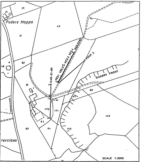
Geophysical surveys of the Kami site
The geophysical programme carried out at Narni has been somewhat
similar to that of Orte, excluding all tests performed in
boreholes. Two high resolution reflection seismic profiles have
been performed: they both had a linear extention of about 100
meters (lines NAR-01-89 and NAR-02-89, see the Figure). Two
geoelectrical profiles (HEL - horizontal electrical lines) have
been performed to evaluate the electrical resistivity of the clay
formation. The first profile covers exactly the seismic line
NAR-02-89; on the same alignment, four vertical electrical soundings
(VES) have been carried out (see Figure). Elaboration of results
is presently being completed.
Structural geology survey of the Narni site
To better define the geostructural setting of the Narni hill a
structural geology survey has been performed. Even if data
elaboration is presently under way, it can be anticipated that the
many dislocations encountered follow the main structural regional
patterns.
-30-SCALE 1:2000