This is a repository copy of
Cache Partitioning + Loop Tiling: A Methodology for Effective
Shared Cache Management
.
White Rose Research Online URL for this paper:
http://eprints.whiterose.ac.uk/120736/
Version: Accepted Version
Proceedings Paper:
Kelefouras, V, Keramidas, G and Voros, N (2017) Cache Partitioning + Loop Tiling: A
Methodology for Effective Shared Cache Management. In: IEEE Computer Society Annual
Symposium on VLSI (ISVLSI 2017). ISVLSI 2017, 03-05 Jul 2017, Bochum, Germany.
IEEE , pp. 477-482. ISBN 9781509067626
https://doi.org/10.1109/ISVLSI.2017.89
(c) 2017, IEEE. Personal use of this material is permitted. Permission from IEEE must be
obtained for all other uses, in any current or future media, including reprinting/republishing
this material for advertising or promotional purposes, creating new collective works, for
resale or redistribution to servers or lists, or reuse of any copyrighted component of this
work in other works.
[email protected] https://eprints.whiterose.ac.uk/
Reuse
Unless indicated otherwise, fulltext items are protected by copyright with all rights reserved. The copyright exception in section 29 of the Copyright, Designs and Patents Act 1988 allows the making of a single copy solely for the purpose of non-commercial research or private study within the limits of fair dealing. The publisher or other rights-holder may allow further reproduction and re-use of this version - refer to the White Rose Research Online record for this item. Where records identify the publisher as the copyright holder, users can verify any specific terms of use on the publisher’s website.
Takedown
If you consider content in White Rose Research Online to be in breach of UK law, please notify us by
Cache partitioning + loop tiling: A methodology for
effective shared cache management
Vasilios Kelefouras
Technological Educational Institute of Western Greece Email: [email protected]
Georgios Keramidas
Technological Educational Institute of Western Greece Email: [email protected]
Nikolaos Voros
Technological Educational Institute of Western Greece Email: [email protected]
Abstract—In this paper, we present a new methodology that
provides i) a theoretical analysis of the two most commonly used approaches for effective shared cache management (i.e., cache partitioning and loop tiling) and ii) a unified framework to fine tuning those two mechanisms in tandem (not separately). Our approach manages to lower the number of main memory accesses by one order of magnitude keeping at the same time the number of arithmetical/addressing instructions in a minimal level. We also present a search space exploration analysis where our proposal is able to offer a vast deduction in the required search space.
I. INTRODUCTION
Efficient shared cache utilization in multicore platforms represents one of the most performance and energy critical problems, especially for data dominant applications. First, uncontrolled data contention occurs among different tasks, because all the cores can unrestrictedly access the entire
shared cache memory [1]. Second, when the total size of
the data structures of the executing application is larger than the cache size and the data are accessed more than once, the data are loaded and reloaded many times from the slow and energy demanding main memory. A well-studied direction to address the first problem is to rely on software cache partitioning techniques, called page coloring [1] [2] [3] [4]. A fruitful approach to circumvent the second problem is by employing compiler level techniques such as loop tiling
[5] [6] and data array transformations [7] [8]. However,
when applying the above optimization techniques, most of the shared cache architecture details and data reuse patterns of the (co-)executing applications are not appropriately taken into consideration. Most importantly, all the related approaches address the two above problems separately.
In this paper a new methodology is presented which ad-dresses the shared cache management problem in a theoret-ical basis taking into consideration the underlying hardware architecture details as well as the memory characteristics of the application (e.g., memory reuse patterns of the executing threads). The proposed methodology assumes a fixed number of threads (each one mapped into a core) and the shared cache architecture details as input and outputs the (near)-optimum tile sizes of the main loops, the shared cache partition sizes, and data array layouts. The goal is to reduce, to the extent
possible, the number of main memory accesses keeping at the same time the number of arithmetical instructions at a minimal level. By iteratively applying the proposed methodology for all the different mappings between threads and cores, the best mapping can be calculated (in terms of main memory accesses), i.e., which threads should run on each core.
We showcase that if the transformations addressed in this paper are included in a iterative compilation process (in order to test all different related binaries), the compilation time will last about1037years (for the algorithms studied here). On the other hand, the compilation time of the proposed methodology lasts from some minutes to some hours. Thus, an efficient schedule can be found in a reasonable amount of time (with the term schedule we refer to a specific transformation parameter set).
The major contributions of this paper are the following: i) for the first time, shared cache partitioning, loop tiling, and data array layout transformations are addressed theoretically but most importantly in a single framework, i.e., as one problem and not separately, ii) cache partitioning and loop tiling are addressed by taking into account the last level cache (LLC) architecture details and the memory characteristics of the co-running applications, iii) a direct outcome of the two previous contributions is that the search space (to fine-tune the above memory management techniques) is decreased by many orders of magnitude.
The experimental results are based on the widely used and cycle/power accurate Gem5 [9] and McPAT [10] simulators. The proposed methodology has been evaluated over eight well known data dominant loop kernels (taken from [11]) in terms of compilation time, main memory accesses, performance and energy consumption.
The remainder of this paper is organized as follows. In Section II, the related approaches are provided. The proposed methodology is described in Section III while experimental
results are presented in Section IV. Finally, Section V
concludes this paper.
II. RELATEDWORK
[3] [2] [4] [12]. [3] proposes a practical OS-level cache management scheme for multicore real time system that uses partitioned fixed priority preemptive scheduling; in this work, cache partitions are allocated to cores not to tasks. In [2], a software runtime library is presented that enables programmers to explicitly manage space sharing and contention in LLC. [4] describes the implementation of a page coloring framework in the Linux kernel. Apart from cache partitioning, researchers tried to increase the the shared cache utilization by employing compiler transformations and most commonly loop tiling
transformations [6] [7] [5] [13] [14]. [6] describes a
method for automatically generating multilevel tiled code for any polyhedral iteration space. [14] presents a cache hierarchy aware tile scheduling algorithm targeting to maximize data reuse in LLC. To the best of our knowledge, this is the first work that proposes a combined scheme in which page coloring and loop tiling are fine tuned in a coordinated way.
III. PROPOSEDMETHODOLOGY
In this paper we make the following assumptions. First, we assume a fixed number of threads; this means that no extra threads are added at runtime. Second, we assume that all the threads are assigned to a core; otherwise, we can randomly assign the threads to the cores and then apply iteratively the proposed methodology for all the different mappings between threads and cores. Moreover, we assume that no more than p tasks can run in parallel (one to each core), where p is the number of the cores in the multicore platform. The proposed methodology uses per-core and not per-task cache
partitioning; this approach has two important benefits [3].
The target applications are static loop kernels (both perfectly and imperfectly nested loops, where all the array subscripts are linear equations of the iterators).
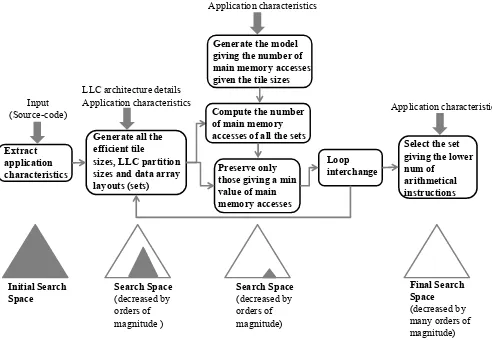
Extract application characteristics
Generate all the efficient tile sizes, LLC partition sizes and data array layouts (sets)
Preserve only those giving a min value of main memory accesses
Loop interchange
Select the set giving the lower num of arithmetical instructions
Input (Source-code)
LLC architecture details Application characteristics
Initial Search Space
Final Search Space
(decreased by many orders of magnitude)
Search Space
(decreased by orders of magnitude )
Search Space
(decreased by orders of magnitude)
Generate the model giving the number of main memory accesses given the tile sizes
Application characteristics
Compute the number of main memory accesses of all the sets
[image:3.612.52.298.459.630.2]Application characteristics
Fig. 1. Flow graph of the proposed methodology
An abstract representation of our methodology is illustrated in Fig. 1. First, parsing is applied and all the loop kernels and their characteristics are extracted. Then, one mathematical equation is created for each array’s subscript, e.g., (A[2∗i+
j]) and (B[i, j]) give (2∗ i+j = c1) and (i = c21 and
j =c22), respectively, where the following integer constants (c1, c21, c22) are found according to the corresponding loop bound values.
Definition 1: Subscript equations which have more than one solution for at least one constant value, are named type2 equations. All others are named type1 equations.
For example, (2∗i+j = c1) is a type2 equation, while
(i=c21and j =c22) is a type1 equation. Type1 and type2
arrays are treated in different ways as their data reuse patterns are different.
The next step is to apply one level of tiling to all the loop kernels of all the tasks. Tiling is applied in order to partition the data arrays into smaller ones (tiles) which fit and remain in the cache during the execution. Therefore, the data arrays are accessed few times from the slow and energy demanding main memory. Although we apply loop tiling to all the loop iterators at the first place, the output schedule/binary may contain tiling to only one or none of the iterators. The tile sizes selection procedure is analyzed in Subsection III-B.
In order to apply loop tiling in an efficient way, we generate one mathematical inequality for each loop kernel giving all the efficient cache partition sizes, tile sizes and shapes. This way, we take into account the cache architecture details and the data reuse. Fig. 2 shows an example of the proposed methodology (it is explained in detail in the next subsections). The tiles have to be small enough in order to fit in the cache and big enough in order to utilize the cache size. To satisfy that the tiles remain in cache, four conditions must simultaneously hold (they are further explained in Subsection III-A). The tile sizes that are different than those provided by the proposed equations are discarded (they are inefficient), reducing the search space.
Given that all the efficient tile and cache partition sizes have been extracted (Subsection III-A), we preserve only those giving a main memory access value close to the minimum, while all the others are discarded further decreasing the search space. The problem of finding the number of main memory accesses is theoretically formulated by exploiting the custom application characteristics (Subsection III-B). In subsection III-B, one mathematical equation is generated for each loop kernel, giving the corresponding number of main memory accesses. The independent variables of this equation are the tile sizes; the tile sizes that minimize this equation achieve the minimum number of main memory accesses.
elements in main memory in order; new arrays are created which replace the default ones (an extra loop kernel is added), b) the number of the loops being tiled is increased (the number of the extra loops being inserted equals to the number of the loops being tiled), c) smaller tile sizes are selected (the number of loop iterations is increased). The constraint (a) gives by far more arithmetical instructions than (b) and (c). Thus, the schedules are classified according to the number of addressing instructions, that is, how many of the (a)-(c) constraints they meet. This way, we can find the schedule giving the smallest number of arithmetical instructions. By iteratively applying the above procedure for all the different mappings between threads-cores, we can find the best mapping (in terms of main memory accesses), i.e., what threads run on each core.
The reminder of this section is divided into two subsections explaining in more detail the most complex steps of Fig. 1.
A. Deriving efficient tile sizes, cache partition sizes, and data array layouts
Loop tiling transformation is the key to the high perfor-mance and low energy SW for data dominant applications. However, as we show in this work, in order to apply loop tiling in an efficient way, the cache size and associativity and the data array layouts must be taken into account as they strongly depend on each other.
In order to find suitable tile and cache partition sizes, a shared cache inequality is produced for each loop kernel providing all the (near)-optimum tile and partition sizes; each inequality contains i) the tile size of each array and ii) the shape of each array tile (e.g., rectangle, line or square). The inequality that provides all the efficient tile sizes and shapes for each loop kernel separately is formulated as:
assoc− ⌊assoc/4⌋ ≤ ⌈ T ile1
LLCi/assoc⌉+...+⌈LLCi/assocT ilen ⌉ ≤assoc (1)
where LLCi is the LLC size / shared cache partition size
used for loop kernel of taski; the number of different partitions
equals to the number of the cores and LLCi = LLC1 for
all the tasks mapped onto the first core; assoc is the LLC
associativity e.g., for an 8-way associative cache,assoc= 8).
(⌊assoc/4⌋) provides the number of cache ways that remain
unused and defines the lower bound of tile sizes (experimen-tally derived). T ilei is the tile size of the ith array and it is
formulated as follows:
T ilei=T1′×T′
2×...×Tn′ ×type×s (2)
wheretypeis the size of each array’s element in bytes and T′
i equals to the tile size of theiiterator, e.g., in Fig. 2, the tile
of C[i][j]isT ileC=T1×T2×4(floating point elements; 4
bytes each).sis an integer and (s= 1ors= 2);sdefines how many tiles of each array should be allocated in LLC according to the data reuse being achieved (it is explained below).
(LLCi/assoc) gives the size of one cache way.
(⌈ T ile1
LLCi/assoc⌉) value in ineq. 1 is an integer that represents
the number ofLLCicache lines with identicalLLCaddresses
used for T ile1. (⌈LLCT ilei/assoc1 ⌉+...+⌈LLCT ilei/assocn ⌉) value in
ineq. 1 gives the number of LLCi cache lines with identical
LLC addresses used for all the tiles; if this value becomes
larger than the (assoc) value, the tiles cannot remain in the cache simultaneously. On the other hand, by using ineq. 1, an empty cache line is always granted for each different modulo (with respect to the size of the cache) of tile memory addresses. For the reminder of this paper we are going to say that (⌈ T ile1
LLCi/assoc⌉) cache ways are used for T ile1 (in
other words tiles are written in separate cache ways). For example, in Fig. 2 the 1st,2nd,3rd terms of eq.13 give the number of ’ways’ used forC, A, Barrays, respectively. In the case that T ilei
LLCi/assoc would be used instead of⌈
T ilei
LLCi/assoc⌉,
the number of cache misses will be larger because tiles would conflict with each other.
In order to satisfy that the tiles remain in the cache, the following four conditions must be met.
First, shared cache is divided intoppartitions (one for each core) and each core uses only its assigned shared cache space. As noted, leveraging the fact that the shared LLC (the target cache level in this work) is typically physically indexed, our cache partitioning mechanism is based on the well known OS technique called page coloring [3]. In particular, when a tasks’s data have to be written onto a specific shared cache color, the virtual memory pages of the tasks are mapped onto specific physical pages that corresponds onto specific page colors. Each processor supports a fixed-maximum number of
partitions (colors) which is given by LLC/(assoc×page),
where LLC, assoc and page are the LLC size, the LLC
associativity, and the main memory page size, respectively. If the maximum number of colors is 32 in a 4-core system
(p = 4), (LLC1 + LLC2 + LLC3 +LLC4 = 32) and
(LLCi = (LLC/32)×d) where d = [1,32] and (i) is the
core id.
Second, in order the tiles to remain in the cache during the whole execution, the tile elements that do not contain consecutive virtual main memory locations must be relocated (re-paged) in consecutive virtual main memory locations, known as tile-wise data array layout (new arrays are created which replace the default ones-an extra loop kernel is added). However, there are some special cases where the arrays do not contain consecutive memory locations but their layouts can remain unchanged. For example, this can happen when the tile size is very small (T ilei ≺ (LLCi/assoc)/8) (this
value has been found experimentally). In this case, first the array layout is not changed and second the tile is not inserted in ineq. 1.
Third, the array tiles directed to the same cache subregions do not conflict with each other i.e., the number of cache lines with identical addresses needed for the array tiles is not larger than the (assoc) value. This is achieved by choosing the correct tile sizes, tile shapes, and data array layouts.
Fourth, for the tiles that do not exhibit data reuse, i.e., if a different tile is accessed in each iteration, we assign cache space twice the size of their tiles; in this way, the next accessed tile does not conflict with the current ones, satisfying
that the tiles remain in cache (data reuse). s value defines
how many tiles (one or two tiles) are allocated in LLC for
each array and (s = 1 or s = 2) depending on whether
the tile is reused or not, respectively. s = 1 is selected for all the tiles that either they are accessed only once, or they are accessed/reused in consecutive iterations (the same tile is accessed in each iteration). Tiles that achieve data reuse contain the iterators with the smallest nesting level values (upper iterators). Otherwise, if a different tile is accessed in each iteration,s= 2is selected; in this case, two consecutive tiles are allocated into LLC in order the second accessed tile not to displace another array’s tile. Let us give an example. Consider the second code of MMM in Fig. 2 assuming that the arrays are written tile-wise in main memory. The three tiles are accessed many times (data reuse) and thus they must remain in the cache. In the case that the three array tiles fit in the cache without any empty cache space left, when the second tile of A and B are loaded and multiplied by each other, some of their elements are going to be written on the tile of C; thus, some of the tile C elements will be loaded again. On the other hand, if we choose smaller tiles for A and B such that one tile of C and two consecutive tiles of A and B fit in the cache, the above problem will never occur and the number of cache misses will be minimized.
B. Deriving the model providing the number of main memory accesses with respect to the tile sizes
In this subsection the number of main memory accesses is derived theoretically by exploiting the unique memory behavior of each loop kernel. More specifically, for each loop kernel one mathematical equation is created providing the corresponding number of main memory accesses. The independent variables of this equation are the tile sizes. Normally, the larger the tile sizes are, the lower the number
of the main memory accesses is (assuming the tiles can remain in the cache). Obviously, larger cache partition sizes implies that larger the tile sizes can be used. However, the tile sizes are constrained by the shared cache architecture details, the designated cache partition size, and the number of the cores/tasks.
Based on the Subsection III-A, no unexpected misses occur (the four conditions explained above hold) and thus the number of main memory accesses can be calculated as follows. The overall number of main memory accesses can be extracted by accumulating all the different loop kernel equations (eq. 3). For the sake of simplicity, in the reminder of this paper we assume that each task contains only one loop kernel.
DDR Acc.=Pi=tasks
i=1 (T askiArrays+codei) (3)
wheretasksis the number of the tasks.T askiArraysand
codei represent the number of main memory accesses due to
the threadidata arrays and source code, respectively (for data
dominant applications (T askiArrays ≫ codei)). The main
memory size allocated for the scalar variables is meaningless and it is ignored. It is important to mention that (codei) value
is slightly affected by the loop tiling transformation and thus it is inserted in eq. 3 as a constant value.
For the rest of this work, we assume that the underlying memory architecture consists of separate first level data and instruction caches (vast majority of architectures). In this case, the program code typically fits in L1 instruction cache; thus, it is assumed that the shared cache space is dominated by the data arrays of the loop kernels.
T askiAcc is given by the following equation:
T askiAcc.=T ype1 array acc.+T ype2 array acc. (4)
where T ype1 array acc. and T ype2 array acc. is the
number of main memory accesses of all type1 and type2
arrays, respectively (for task i). T ype1 array acc. and
T ype2 array acc.are offered by eq. 5 and eq. 7, respectively.
T ype1 array acc.=Pii==1arrays1(ArraySizei×ti+of f seti) (5)
wherearrays1is the number of type1 arrays,ArraySizei
is the size of arrayiandtirepresents how many timesarrayi
is accessed from main memory.of f seti gives the number of
main memory data accesses that occur when the data array layout of array iis changed. Offset is either (of f seti = 2×
ArraySizei) or (of f seti= 0) depending on whether the data
layout of arrayiis changed or not; in the case that the layout of arrayiis changed, the array has to be loaded and then written again to main memory, thus it is (of f seti= 2×ArraySizei).
ti gives how many times arrayi is accessed from main
memory and is given by:
ti=Qjj==1N
upj−lowj
stepj ×
Qk=M k=1
upk−lowk
stepk (6)
whereN is the number of iterators exist above the upper
M is the number of iterators exist between the new iterators of this array (e.g., jj iterator for A array), if any. upj,lowj,
stepj are the bound values of the corresponding new iterator
(in Fig. 2, upii =N, lowii = 0, stepii =T1), e.g., in Fig. 2
and MMM, eq. 6 gives (tA = TN2) and (tB = TN1), for A, B
arrays, respectively. The first and the second products of eq. 6 give how many times the array is accessed due to the iterators exist above the upper new iterator of this array and between the new iterators of this array, respectively, e.g., the B array
in Fig. 2 does not contain ii iterator and thus it is loaded
(N/T1) times (the same holds for A array which is loaded
(N/T2) times).
The number of main memory data accesses of type2 arrays is calculated as follows:
T ype2array acc.=
i=arraysX 2
i=1 (ti×
up1−low1
step1 ×
×((up2−low2) +step1)×((up2′−low2′) +step1′) +of f set
i)
(7)
where arrays2 is the number of type2 arrays, ti is
cal-culated by eq. 6, up1, low1, step1 are the bound values of the outermost type2 new/tiling iterator (e.g.,ii iterator forin array in Fig. 2) andup2, low2are the upper/lower bounds of the innermost type2 new/tiling iterator (e.g., jj iterator for in array in Fig. 2), e.g., (up1, low1, step1, up2, low2) values of in array in Fig. 2 are (N,0, T4, M,0); without any loss of generality we assume that the type2 equations contain only two iterators here. If only 1 iterator has been tiled, it refers to the up1, low1, step1 (up2, low2 refer to the other iterator that has not been tiled). For 1-dimensional arrays the
((up2′−low2′) +step1′)term is ignored; for 2-dimensional
arrays this term refers to the (up2, low2, step1) values of the second subscript.
In practice, type2 arrays are accessed more times than type1 arrays because of the extra iterators they contain; when more than one iterator exists in a single subscript (e.g.,in[i+j]array in Fig. 2), data patterns occur which they are repeated/accessed many times. For example, as the innermost iterator in FIR (Fig. 2) changes its value, the elements are accessed in a pattern, i.e., A[2],A[3],A[4]etc. When the second innermost iterator (i) changes its value, this pattern is repeated, shifted by one position to the right (A[3],A[4],A[5]etc), reusing its elements. This holds for equations with more than 2 iterators too. The ((up2−low2) +step1×((up2′−low2′) +step1′))
part in eq. 7 gives the size of the pattern in the general case (2-d array) while (upstep1−low1 1) offers how many times the pattern is repeated/accessed. It is important to say that eq. 7 holds when ((pattern size)−tile size) ≥tile size); otherwise, the array is accessed only once and eq. 6 changes accordingly. An example is given in Fig. 2.
IV. EXPERIMENTALRESULTS
Our experimental results are based on gem5 [9] and McPAT [10] simulators. The comparison is done for 8 well-known data dominant kernels of linear algebra, image processing, and signal processing ( [11]). gem5 is used to simulate a x86 multicore architecture at 2Ghz with a 1MB L2 shared cache.
//MMM
for (i=0;i!=N;i++) for (j=0;j!=N;j++)
for (k=0;k!=N;k++) C[i][j]+= A[i][k] * B[k][j];
//MMM after loop tiling for (ii=0; ii!=N; ii+=T1)
for (jj=0; jj!=N; jj+=T2) for (kk=0; kk!=N; kk+=T3)
for (i=ii; i!=ii+T1; i++) for (j=jj; j!=jj+T2; j++)
for (k=kk; k!=kk+T3; k++) C[i][j]+= A[i][k] * B[k][j];
MMM - Main Memory accesses
C: 2 x N2
A: N3/T2
B: N3/T1
mmm_acc.= 2xN2 + N3/T2 + N3/T1 //FIR
for (i=0;i!=N;i++) for (j=0;j!=M;j++)
out[i] += in[ i + j ] * kernel[ j ];
//FIR after loop tiling for (ii=0; ii!=N; ii+=T4)
for (jj=0; jj!=M; jj+=T5) for (i=ii; i!=ii+T4; i++)
for (j=jj; j!=jj+T5; j++) out[i] += in[ i + j ] * kernel[ j ];
FIR - Main Memory accesses
out: 2 x N in: N/T4 x (M+T4) kernel: M x N/T4
fir_acc.= 2xN + N/T4 x (M+T4) + M x N/T4 Equation giving the number of main memory accesses:
DDR-acc = Offset + mmm_acc. + fir_acc. + code (8)
Offset = 0 , if (T3=N & T2=N) (9)
Offset = 2xN2 T N T N (10)
Offset = 4xN2 T N T N (11)
Offset = 6xN2 T N T N (12)
Equation giving all the efficient tile and LLC partition sizes for MMM
4
1 2 1 +
1 3 2 1 +
2 3 2
1 (13)
Equation giving all the efficient tile and LLC partition sizes for FIR
4 4
2 + 4+ 5
2 + 5
2 (14)
LLC1+LLC2=LLC (15)
LLC1=LLC/d, d=[1,max_colors] (16)
LLC2=LLC/d, d=[1,max_colors] (17)
(0 < T1, T2, T3, T4 < N) & (0 < T5 < M) (18)
Fig. 2. Motivation example of Subsection III-A and Subsection III-B
TABLE I
EVALUATION OF THE ACCURACY OFSUBSECTIONIII-B
Loop kernel Input size 1 Error Input size 2 Error mmm (800,800,800) 1.85% (1200,1200,1200) 2.10%
fir (20000,4000) 2.35% (80000,8000) 2.43% mvm (4000,4000) 1.10% (8000,8000) 1.20% gesumv (4000,4000) 1.30% (8000,8000) 1.30% doitgen (100,100,100,100) 2.20% (200,200,200,1000) 2.10% symm (608,608,608) 2.45% (1200,1200,1200) 2.51% Gauss Blur (512,512) 0.00% (1024,1024) 0.00% Seidel2d (512,512) 0.00% (1024,1024) 0.00%
First, an evaluation of the accuracy of Subsection III-B has been made. Table I illustrates the main memory data accesses calculated by the equations of Subsection III-B and from gem5 simulator. The error values are also depicted. As we can observe, the error is small in both input sizes for all the kernels. In Gaussian Blur and the Seidel2d kernels, the error is zero because the critical part of the arrays fits in the shared cache, thus the arrays are fetched only once from the main memory (no loop tiling is applied). We did not use larger input sizes for these two kernels because in our opinion, they are not realistic.
also been made over iterative compilation. Simple speaking, we calculate the number of different binaries related in this paper. The search space consists of all the different tile sizes and shapes, data array layouts, cache partition sizes, and nesting level values. It is given by:
Schedules= (max colors−1)! (cores!)×(max colors−cores)!
×
×
iY=N
i=1
((2d arraysi×2)×T ileloopsi
i ×(2×loopsi!))
(19)
whereN is the number of the loop kernels, whilecoresand
max colors are the number of the cores and cache colors,
respectively. 2d arraysi is the number of multidimensional
arrays in loop kernel i and indicates that each
multidimen-sional array uses two different data layouts (the default and the tile-wise), T ilei is the number of different tile sizes for
loop kerneli andloopsi is the number of the loops of kernel
i. For a fair comparison, we use only (T ile= 20) different tile sizes for all the loop kernels.
Based on eq. 19, the overall number of binaries that eq. 19 gives is3.37×1044 (cores= 8andcolors= 32). Given that 1sec= 3.17×10⁻⁸yearsand supposing that compilation time
takes about 1 sec, the compilation time is about 1037 years.
Instead of testing all those schedules (which is impractical), the proposed methodology finds the best schedule among those in a significantly smaller fraction of time (from minutes to hours).
Moreover, an evaluation over gcc 4.8.4 compiler has been performed, in terms of main memory data accesses, perfor-mance and energy consumption (Table II). We have used four cores and eight loop kernels. Six different thread com-binations have been used with three different input sizes
(Table II). The thread combination numbers correspond to
(1,2,3,4,5,6,7,8)=(mmm, mvm, symm, fir, gesumv, seidel, doit-gen, gauss). The first and the fourth kernel combinations en-gender a higher cache pressure and they produce the smallest ddr access gain values and consequently the smallest speedup and energy gain values. This is because in the first and fourth cases, the three most data dominant kernels (doitgen, symm, mmm) run on a different core and thus they compete to each other for cache space. On the other hand, on the other combinations two of the three above kernels use the same core and thus only the two kernels compete to each other for cache space.
TABLE II
FOUR CORES AND EIGHT LOOP KERNELS,TWO TO EACH CORE
kernel combinations DDR gain speedup energy gain (1-2,3-4,5-6,7-8) 15.48 1.71 1.78 (1-3,2-4,5-6,7-8) 25.43 1.75 1.86 (8-2,3-4,5-6,7-1) 22.6 1.72 1.85 (1-5,4-3,6-7,2-8) 16.31 1.71 1.8 (6-8,7-5,3-1,2-4) 26.06 1.76 1.88 (6-8,5-2,3-4,1-7) 22.04 1.72 1.84
V. CONCLUSION
In this paper a novel methodology is presented providing a theoretical foundation in the shared cache partitioning and loop tiling problems, in tandem (not separately). This methodology reduces the number of main memory data accesses from 7.72 up to 25 times, the execution time of about 1.7 and the energy consumption of about 1.8.
ACKNOWLEDGMENT
This study is part of the collaborative project ARGO, which is funded by the European Commission under Horizon 2020 Research and Innovation Action, Grant Agreement Number 688131
REFERENCES
[1] D. Tam, R. Azimi, L. Soares, and M. Stumm, “Managing shared l2 caches on multicore systems in software,” inWorkshop on the Interaction between Operating Systems and Computer Architecture, 2007. [2] X. Ding, K. Wang, and X. Zhang, “Ulcc: a user-level facility for
optimizing shared cache performance on multicores.” inPPOPP. ACM, 2011, pp. 103–112.
[3] K. Hyoseung, K. Arvind, and R. Ragunathan, “A coordinated approach for practical os-level cache management in multi-core real-time sys-tems,” in25th ECRTS, Paris, France, July 9-12, 2013, pp. 80–89. [4] Y. Ye, R. West, Z. Cheng, and Y. Li, “Coloris: A dynamic cache
partitioning system using page coloring,” ser. PACT ’14. ACM, 2014, pp. 381–392.
[5] B. Bao and C. Ding, “Defensive loop tiling for shared cache,” in
Proceedings of the 2013 IEEE/ACM International Symposium on Code Generation and Optimization (CGO), ser. CGO ’13. Washington, DC, USA: IEEE Computer Society, 2013, pp. 1–11.
[6] D. Kim, L. Renganarayanan, D. Rostron, S. Rajopadhye, and M. M. Strout, “Multi-level tiling: M for the price of one,” inProceedings of the 2007 ACM/IEEE Conference on Supercomputing, ser. SC ’07. ACM, 2007, pp. 51:1–51:12.
[7] I.-J. Sung, J. A. Stratton, and W.-M. W. Hwu, “Data layout transforma-tion exploiting memory-level parallelism in structured grid many-core applications,” inProceedings of the 19th International Conference on Parallel Architectures and Compilation Techniques, ser. PACT ’10. New York, NY, USA: ACM, 2010, pp. 513–522.
[8] Y. Zhang, W. Ding, M. Kandemir, J. Liu, and O. Jang, “A data layout op-timization framework for nuca-based multicores,” inProceedings of the 44th Annual IEEE/ACM International Symposium on Microarchitecture, ser. MICRO-44. ACM, 2011, pp. 489–500.
[9] N. Binkert, B. Beckmann, G. Black, S. K. Reinhardt, A. Saidi, A. Basu, J. Hestness, D. R. Hower, T. Krishna, S. Sardashti, R. Sen, K. Sewell, M. Shoaib, N. Vaish, M. D. Hill, and D. A. Wood, “The gem5 simulator,”
SIGARCH Comput. Archit. News, vol. 39, no. 2, pp. 1–7, Aug. 2011. [10] S. Li, J. H. Ahn, R. D. Strong, J. B. Brockman, D. M. Tullsen, and
N. P. Jouppi, “Mcpat: An integrated power, area, and timing modeling framework for multicore and manycore architectures,” inProceedings of the 42Nd Annual IEEE/ACM International Symposium on Microar-chitecture, ser. MICRO 42. ACM, 2009, pp. 469–480.
[11] O. S. University. (2012) Polybench/c benchmark suite. [Online]. Available: http://web.cs.ucla.edu/ pouchet/software/polybench/ [12] X. Zhang, S. Dwarkadas, and K. Shen, “Towards practical page
coloring-based multicore cache management,” in Proceedings of the 4th ACM European Conference on Computer Systems, ser. EuroSys ’09. ACM, 2009, pp. 89–102.
[13] X. Zhou, J.-P. Giacalone, M. J. Garzar´an, R. H. Kuhn, Y. Ni, and D. Padua, “Hierarchical overlapped tiling,” inProceedings of the Tenth International Symposium on Code Generation and Optimization, ser. CGO ’12. ACM, 2012, pp. 207–218.