Iterative Receiver Architectures for MIMO-OFDM
Jos Akhtman and Lajos Hanzo
School of ECS, Univ. of Southampton, SO17 1BJ, UK.
Tel: +44-23-80-593 125, Fax: +44-23-80-593 045
Email: [email protected], http://www-mobile.ecs.soton.ac.uk
Abstract— In this paper we propose a turbo-detected multi-antenna-multi-carrier receiver scheme. Following the philosophy of the turbo processing, our turbo MIMO-OFDM receiver comprises a succession of detection modules, namely the channel estimator, the space-time detector and the decoder, which itera-tively exchange soft bit-related information and thus facilitate a substantial improvement of the overall system performance. In this paper we analyse the achievable performance of the iterative system proposed with the aim of documenting the various design trade-offs, such as the achievable error-rate performance, the attainable data-rate as well as the associated computational com-plexity. Specifically, we report a virtually error-free performance for a rate-12 turbo-coded 8x8-QPSK-OFDM system, exhibiting an effective throughput of 8·2·12=8 bits/sec/Hz and having a pilot overhead of only 10%, at SNR of 7.5dB and normalized Doppler frequency of 0.003, which corresponds to a mobile terminal speed of about 65 km/h.
I. INTRODUCTION
Channel Estimator
Space-Time Detector
y y
H
c d
turbo decoder joint detector-decoder
extr. info.
extr. info.
extr. info. Code 1
[image:1.595.40.293.370.488.2]Code 2
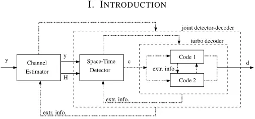
Fig. 1. Schematic of an iterative turbo receiver employing an iterative decision-directed channel estimation, detection and decoding modules.
Despite the immense interest of both the academic and the industrial research communities, the conception of a practical multiple-input multiple-output (MIMO) transceiver architec-ture, which is capable of approaching the MIMO channel’s capacity in realistic channel conditions remains largely an open problem. An important overview encompassing most major aspects of broadband MIMO-OFDM wireless communi-cations including both channel estimation and signal detection, as well as time- and frequency-domain synchronization was contributed by St¨uber et al. [1]. Other important publications considering MIMO systems operating in realistic channel con-ditions include those by M¨unster and Hanzo [2], Liet. al.[3],
Acknowledgements: The work reported in this paper has formed part of the Wireless Enabling Techniques work area of the Core 4 Research Programme of the Virtual Centre of Excellence in Mobile and Personal Communications, Mobile VCE, www.mobilevce.com, whose funding support, including that of EPSRC, is gratefully acknowledged. Fully detailed technical reports on this research are available to Industrial Members of Mobile VCE.
Maiet. al.as well as Qiaoet. al.[4]. Nevertheless, substantial
contributions addressing all the major issues pertaining to the design of MIMO transceivers, namely error correction, space-time detection as well as channel estimation in realistic channel conditions remain scarce.
Against this background, in this paper we discuss an it-erative, so called turbo multi-antenna-multi-carrier (MAMC) receiver architecture. Our turbo receiver is illustrated in Fig-ure 1. Following the philosophy of turbo processing [5], our turbo MIMO-OFDM receiver comprises a succession of detection modules, which iteratively exchange soft bit-related information and thus facilitate a substantial improvement of the overall system performance.
More specifically, our turbo MIMO-OFDM receiver com-prises three major components, namely the soft-feedback aided decision-directed channel estimator (DDCE) [6], followed by the soft-input-soft-output optimized-hierarchy reduced search algorithm (OHRSA) Log-MAP MIMO detector [7] as well as a classic parallel-concatenated soft-input-soft-output turbo code [8]. Consequently, in this paper we would like to analyze the achievable performance of the entire iterative system. Our aim is to document the various design trade-offs, such as the achievable error-rate performance, the attainable data-rate as well as the associated computational complexity.
II. CHANNELESTIMATION FORMIMO-OFDM
ˇ H[n]
y[n] ˆ s[n]
ˆs[n] y[n]
CTF Hˆ[n] CIR CIR
Predictor Estimator
Estimator
ˆ
α[n] αˇ[n+1] Hˇ[n+1]
Decoder Detector
˜ WH[n]
˜s[n] ˆs[n]
Decision Directed Channel Estimator
Fig. 2. Schematic of a generic receiver employing DDCE scheme constituted by an a posteriori decision-directed CTF Estimator, followed by a CIR Estimator and ana prioriCIR predictor.
The schematic of the channel estimation method considered is depicted in Figure 2. Our channel estimator is constituted by a soft-inputa posteriori decision-directed channel transfer function (CTF) estimator [6] followed by a projection approx-imation subspace tracking (PAST)-aided [9] channel impulse
[image:1.595.306.554.480.623.2]response (CIR) etimator [10] and an a priori CIR predictor [10]. As seen in Figure 2, the task of the CTF estimator is to calculate the soft-decision aided temporary estimates H[˜ n] of the CTF coefficients. Subsequently, the task of the CIR estimator is to track the estimatesαˆl[n]of the CIR taps, which
are then fed into the low-rank time-domain CIR tap predictor of Figure 2 for the sake of producing an a priori estimate ˇ
αl[n+1], l = 0, 1,· · ·,L of the next CIR on a CIR
[image:2.595.42.291.246.329.2]tap-by-tap basis [10]. Finally, the predicted CIR is converted to the CTF with the aid of the tranformation matrix W[n] of Figure 2. The resultant CTF is employed by the receiver for the sake of detecting and decoding of the next OFDM symbol.
III. ITERATIVECHANNELESTIMATION– DETECTION– DECODING
0000 0000 0000 0000
1111 1111 1111 1111
0000 0000 0000 0000
1111 1111 1111 1111
0 0 0 0 0
1 1 1 1 1
000 000
111 111
000 000
111 111
transmission burst preamble
pilot OFDM symbols data OFDM symbols
OFDM-symbol frame 1
1 2 Np 1 2 Nd 1 2 Nd
2 Lf
[image:2.595.332.528.358.400.2]bit-interleaved
Fig. 3. OFDM transmission burst structure comprising a preamble of Np full-pilot OFDM symbols followed by a sequence of Lf data
OFDM-symbol frames. Each data OFDM-OFDM-symbol frame is preceded by a single full-pilot OFDM symbol followed by Nd information-carying OFDM symbols.
Consequently, our OFDM transmission burst accommodates a total number of Np+Lf full-pilot OFDM symbols as well as a total number ofLfNd
information-carrying OFDM symbols.
In this paper we consider the transmission of a sequence of consecutive MIMO-OFDM transmission bursts, which are processed independently. In other words, each of the self-contained MIMO-OFDM transmission bursts includes all the necessary data, such as for instance pilot signals, required for successful detection and decoding of the information accommodated by the burst. Correspondingly, each MIMO-OFDM transmission burst may be processed independently of the neighbouring bursts. This philosophy is reminiscent of the packet-based transmission scheme adopted, for example, in the IEEE 802.11 a/g WLAN standard [11]. The structure of a single MIMO-OFDM transmission burst considered is depicted in Figure 3. More specifically, our OFDM transmis-sion burst portrayed in Figure 3 commences with a channel-sounding preamble formed by Np number of pure pilot
MIMO-OFDM symbols. Subsequently, our MIMO-OFDM transmission burst accommodates a sequence of Lfnumber of
so-called OFDM-symbol-frames. More explicitely, as seen in Figure 3, each OFDM-symbol-frame constitutes a single bit-interleaved turbo-encoded codeword and comprises a single full-pilot MIMO-OFDM symbol followed by Nd number of
information-carrying MIMO-OFDM symbols.
For each MIMO-OFDM transmission burst the detection process commences with the initialization of the channel estimator by utilizing the pilot MIMO-OFDM symbols consti-tuting the burst’s preamble, as seen in Figure 3. Specifically, both the received signals y[n] as well as the corresponding
transmitted signals s[n] associated with the Np pilot
MIMO-OFDM symbols constituting the burst preamble of Figure 3 are sequentially fed into the channel estimator of Figure 2 for the sake of attaining an initial convergence for the three adaptive filters constituting the decision-directed channel estimator of Figure 2.
During the first iteration of the detection process, which is carried out for each subsequent Nd-OFDM-symbol
data-frame of Figure 3 that commences with a full-pilot MIMO-OFDM symbol associated with the MIMO-MIMO-OFDM-symbol index n, we perform a long-term prediction of the CIR-related taps using the CIR tap predictor of Figure 2. More specifically, we aim for predicting the CIR associated with the last OFDM symbol of the current OFDM-symbol-frame of Figure 3, namely the one associated with the MIMO-OFDM-symbol index of(n+Nd). The CIRs associated with
the remaining (Nd−1) MIMO-OFDM symbols hosted by
the current OFDM-symbol-frame are then obtained using linear interpolation between those associated with the nth pilot MIMO-OFDM symbol preceding the current OFDM-symbol-frame and the predicted CIR associated with the last
(n+Nd)data OFDM symbol. The predicted and interpolated
MIMO-CTF coefficients Hˇ[m], m = n+1, . . . ,n+Nd are
utilized for the sake of performing an initial detection of the information-carrying data MIMO-OFDM symbols s[n].
Iterative Detector
y
ˆ H ˜s
y
ˆ d
DDCE Iterative
&Decoder
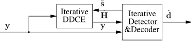
Fig. 4. Schematic of an iterative turbo receiver employing the iterative decision-directed channel estimator of Figure 2 as well as the iterative detection and decoding module.
The resultant tentative estimates of the data-bits d, as well as the associated soft-bit information, corresponding to the entire data MIMO-OFDM-symbol frame of Figure 3 are remodulated in order to generate the soft reference signal ˜
s[m], m = n+1, . . . ,n+Nd [6]. The reference signal
˜
s[m] is fed back to the soft-input channel estimator [6] for the sake of refining the estimates of the CTF coefficients H[m], m= n+1, . . . ,n+Nd. The interaction between the
soft-input channel estimator and the iterative MIMO detection and decoding module is illustrated in Figure 4. The iterative channel estimation–detection–decoding process portrayed in Figure 4 is repeated, until a sufficiently reliable detected MIMO-OFDM symbol ˆsis generated.
A. Mitigation of Error Propagation
divergence of the iterative channel estimation – data detection process and in a subsequent avalanche of decision errors. As was pointed out in [6], the soft feedback aided RLS CTF estimator is capable of substantially mitigating the effects of error propagation. Nevertheless, ensuring the stability of an iterative channel estimation – data detection system in the presence of data decision errors remains a challenging issue. Consequently, for the sake of mitigating the system’s vulnerability to error-propagation-related instability effects we propose the following method.
Firstly, after each channel estimation and MIMO detection iteration, which is performed on the Nd-MIMO-OFDM
sym-bol data frame of Figure 3, we record the resultant MSE. The joint channel estimation and MIMO detection MSE may be expressed as follows
ei[n] = n+Nd
∑
m=n+1
K
∑
k=1
y[m,k]−Hˆi[m,k]ˆsi[m,k]2, (1)
where, as before,y[m,k]denotes the MIMO signal associated with the kth subcarrier of the mth MIMO-OFDM symbol and recorded at the nr receive antennas, while Hˆi[m,k] and ˆ
si[m,k]are the corresponding estimates of the CTF coefficient matrix and the transmitted signal vector, which were obtained after the ith iteration of the channel estimation and detection process.
Subsequently, after carrying outice number of channel esti-mation iterations we select the particular pair of CTF estimates
ˆ
Hi[m,k] and data estimates sˆi[m,k], which correspond to the specific iteration resulting in the minimum MSE. More explicitely, the decision rule employed may be expressed as
ˆ
H[m,k], ˆs[m,k]=arg min
i e
i[n], (2)
where we have m = n+1,· · ·,n+Nd; k =1,· · ·,K and i=1,· · ·,ice.
Let us now consider the scenario of encountering a large number of decision errors. Naturally, the decision errors in any of the iterations would result in a degraded channel estimation accuracy in the subsequent iteration and hence even more decision errors as well as an inevitable increase of the corresponding MSE ei[n]. Consequently, invoking the
final-decision rule of Equation (2) substantially mitigates the system’savalanche-like error propagation and hence improves the system’s stability and robustness.
[image:3.595.305.555.51.266.2]IV. PERFORMANCEANALYSIS
TABLE I SYSTEM PARAMETERS.
Parameter Value
Carrier frequency fc 2.5GHz
Channel bandwidthB 8MHz
Number of carriersK 128
FFT frame durationTs 16µs
OFDM symbol durationT 20µs (4µs of cyclic prefix)
Max. delay spreadτmax 4µs
Max. terminal speedv 130km/h
Norm. Max. Doppler spread fD 0.006=T·300Hz
10-5 10-4 10-3 10-2 10-1 100
0 5 10 15 20
BER
Eb/N0 [dB] iter-logmap-turbo-past-4x4-it-fd0.003-fuzzy : 24-Jul-2006
ice =1 ice =2 ice =3 ice =4 fD=0.003
ε=0.1,4x4 (idet,idec)=(2,4)
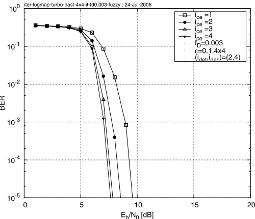
Fig. 5. BER versus Eb/N0 performance exhibited by the rate-12
turbo-coded 4x4-MIMO-4QAM-OFDM iterative turbo receiver of Figure 4 invoking ice = 1, 2, 3 and 4 channel estimation iterations as well as (idet,idec) =
(2, 4)MIMO detection and turbo decoding iterations, respectively. The 7-path COST-207 BU channel model [12] was used and we assumed encountering the OFDM-symbol-normalized Doppler frequency of fD=0.003. The effective
throughput was4·2·12=4bits/sec/Hz. All additional system parameters are summarized in Table I.
1) Number of Channel Estimation – Detection Iterations:
Firstly, we would like to characterize the BER performance gain attained by the iterative MIMO-PASTD-DDCE in com-parison to single-iteration channel estimation. More specifi-cally, Figure 5 portrayes the BER versus Eb/N0performance of the rate1/2turbo-coded 4x4-MIMO-QPSK-OFDM system invoking ice = 1, 2, 3 and 4 channel estimation iterations as well as idet = 2 MIMO detector iterations and idec = 4 iterations of the parallelly-concatenated turbo decoder per each iteration of the channel estimator. We assumed employing the transmission burst structure depicted in Figure 3, where the corresponding parameters were given by (Lf,Np,Nd) =
(8, 8, 10), which yields an overall pilot overhead of ε =
(Np+Lf)/(LfNd) = 0.1, or in other words 10%. The
7-path COST-207 BU channel model was used and we assumed encountering the Doppler frequency of fD=0.003. As may be
concluded from Figure 5, the MIMO-OFDM system proposed exhibits anEb/N0gain of about 2 dB, when comparing three iterations and a single iteration of the channel estimator. More-over, only a modest furtherEb/N0gain may be achieved upon invoking a higher number of channel estimation iterations.
2) Pilot Overhead: In order to provide further insights,
Figure 6 characterizes the achievable BER versus Eb/N0 performance exhibited by the 4x4-MIMO-QPSK-OFDM turbo receiver of Figure 4 employing different mt andnr numbers of transmit and receive antennas. Specifically, we consider in-voking(ice,idet,idec) = (3, 2, 4)channel estimation, detection and decoding iterations, respectively, while employing mt =
[image:3.595.55.279.608.720.2]10-5 10-4 10-3 10-2 10-1 100
0 5 10 15 20
BER
Eb/N0 [dB] iter-past-logmap-turbo-mtx-fd0.003 : 20-Jul-2006
1x1 2x2 4x4 6x6 8x8
[image:4.595.48.558.52.269.2]ε=0.1,fD=0.003
Fig. 6. The BER versus Eb/N0 performance exhibited by the rate-12
turbo-coded MIMO-QPSK-OFDM turbo receiver of Figure 4 using mt =
nr = 1, 2, 4, 6 and 8 transmit and receive antennas. The corresponding
effective throughputs were1, 2, 4, 6and8·2·12 =8bits/sec/Hz, respectively. The 7-path COST-207 BU channel model was used [12] and we assumed encountering the Doppler frequency of fD = 0.003. The pilot overhead
of 10% and the iteration pattern of (ice,idet,idec) = (3, 2, 4)were used.
Additional system parameters are summarized in Table I.
as it does not exceedmt=nr =4. Furthermore, the BER per-formance degrades slowly upon further increasing the number of antennas according tomt=nr>4. The simple explanation of this phenomenon is that as expected, the MIMO-OFDM system benefits from the increased spatial diversity associated with a higher number of antennas. On the other hand, as noted in Section II, the channel estimation problem becomes increas-ingly more rank-deficient and hence the estimation accuracy of the CIR taps as well as the corresponding subcarrier-related CTF coefficients degrades upon increasing the number of independent spatial links constituting the MIMO channel. The overall system performance is determined by the associated trade-off between the beneficial diversity gain increase and the inevitable degradation of the estimated CTF accuracy. Ultimately, however, the deterioration of the estimated CTF accuracy does not appear to constitute a major impediment. Quantitatively, as evidenced by the results of Figure 6, the BER performance exhibited by the high-complexity system having mt = nr = 8 antennas lies within a 1 dB margin in comparison to the corresponding BER performance curve associated with the system having mt = nr = 4 transmit and receive antennas. Observe that the 4x4 system exhibits the best recorded performance and hence appears to represent an optimum tradeoff between the beneficial special diversity gain and the system-size-related channel estimation accuracy degradation.
3) Performance of a Symmetric MIMO System:
Subse-quently, we would like to characterize the achievable BER performance exhibited by the MIMO-QPSK-OFDM turbo receiver of Figure 4 using various densities of the dedicated pilot MIMO-OFDM symbols. More specifically, in Figure 7
10-5 10-4 10-3 10-2 10-1 100
0 5 10 15 20
BER
Eb/N0 [dB] past-4qam-4x4-frame-fd0.003-fuzzy : 24-Jul-2006
perfect CSI ε=1.0 ε=0.3 ε=0.1 ε=0.03 4x4,fD=0.003 (ice,idet,idec)=(3,2,4)
Fig. 7. BER versusEb/N0performance exhibited by the rate-12turbo-coded
4x4-MIMO-QPSK-OFDM turbo receiver of Figure 4. The pilot overhead was either 3, 10, 30, or 100%, which corresponds to ε=0.03, 0.1, 0.3and1.0, respectively, where we consider the idealistic scenario of having 100% pilots as well as the scenario of perfect channel state information for benchmarking purposes. The 7-path COST-207 BU channel model [12] was used and the Doppler frequency was fD=0.003. The iteration pattern of(ice,idet,idec) =
(3, 2, 4)was used and the effective throughput was4·2·1
2 =4bits/sec/Hz.
All additional system parameters are summarized in Table I.
we have plotted the rate 1/2turbo-coded QPSK-related BER exhibited by our MIMO-OFDM system employing mt = nr transmit and receive antennas. For benchmarking purposes we have included the BER versus Eb/N0 performance of the MIMO-OFDM system assuming perfect CIR knowledge, as well as assuming channel estimation based on the idealistic scenario of having 100% pilots. Furthermore, we present our results for the MIMO-OFDM system using pilot overheads of 30, 10 and 3%, which corresponds to the pilot overhead ratio ofε=0.3, 0.1and0.003, respectively. We observe from Figure 7 that the 100% pilot-based channel estimation results in an approximately 1 dBEb/N0degradation in comparison to the perfect CIR estimation scenario. Furthermore, the more re-alistic assumption of employing up to 10% dedicated MIMO-OFDM pilot symbols results in a furtherEb/N0degradation of about 1.5 dB in comparison to the 100% pilot-based scenario. Additionally, a further reduction of the pilot overhead to as low as 3% of pilots results in an Eb/N0 degradation of 2.5 dB in comparison to the 100% pilot-based scenario.
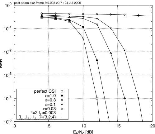
4) Performance of a Rank-Deficient MIMO System: Similar
phenomena may be observed in Figure 8, which characterizes the achievable BER performance exhibited by a rank-deficient 4x2-MIMO-QPSK-OFDM system. The 4x2 MIMO scenario constitutes a particularly interesting detection problem. More specifically, let us consider the kth subcarrier of the nth MIMO-OFDM symbol. The computational challenge lies in the fact that we have to estimate as many as fourtransmitted M-QAM symbols sj[n,k], j = 1, . . . , 4 as well as the
corresponding eight CTF coefficients Hij[n,k],i = 1, 2, j =
sam-10-5 10-4 10-3 10-2 10-1 100
0 5 10 15 20
BER
Eb/N0 [dB] past-4qam-4x2-frame-fd0.003-z0.7 : 24-Jul-2006
[image:5.595.43.292.51.265.2]perfect CSI ε=1.0 ε=0.3 ε=0.1 ε=0.03 4x2,fD=0.003 (ice,idet,idec)=(3,2,4)
Fig. 8. BER versus Eb/N0 performance exhibited by the rank-deficient
rate-12turbo-coded 4x2-MIMO-QPSK-OFDM turbo receiver of Figure 4. The pilot overhead was either 3, 10, 30, or 100%, which corresponds to ε =
0.03, 0.1, 0.3and1.0, respectively, where we consider the idealistic scenario of having 100% pilots as well as the scenario of perfect channel state information for benchmarking purposes. The 7-path COST-207 BU channel model was used [12] and the Doppler frequency wasfD=0.003. The iteration pattern of (ice,idet,idec) = (3, 2, 4)was used and the effective throughput was4·2·12 = 4bits/sec/Hz. All additional system parameters are summarized in Table I.
ples ofyi[n,k], i =1, 2. Consequently, similarly to Figure 7
we have plotted the BER versus Eb/N0 performance of the 4x2-MIMO-QPSK-OFDM system assuming perfect CSI as well as assuming channel estimation based on the idealistic scenario of having 100% pilots. Furthermore, we have plot-ted the BER corresponding to the scenarios of using pilot overheads of 30, 10 and 3%. Similarly to the 4x4 scenario, assuming 100% pilot-based channel estimation results in an approximately 1 dB Eb/N0 degradation in comparison to the perfect CIR knowledge scenario. On the other hand, in contrast to the 4x4 scenario characterized in Figure 7, in Figure 8 we may observe that the system employing 10% of dedicated MIMO-OFDM pilot symbols results in nearly 6 dB Eb/N0 degradation in comparison to the 100% pilot-based scenario. Furthermore, an additional reduction of the pilot overhead to 3% of pilots results in a system instability and hence no satisfactory BER performance may be achieved, regardless of the SNR encountered.
V. CONCLUSIONS
In this paper we have documented the performance trends exhibited by the proposed turbo MIMO-OFDM receiver of Figure 1, which comprises three major components, namely, the soft-feedback decision-directed MIMO channel estimator outlined in Section II, followed by the soft-input-soft-output OHRSA Log-MAP MIMO detector [7] as well as a soft-input-soft-output parallel-concatenated turbo code [8]. As seen in Figure 6, we have found that our turbo SDM-OFDM system employing the MIMO-DDCE scheme of Section II as well as the OHRSA Log-MAP SDM detector [7] exhibits
a virtually error-free performance for a rate-12 turbo-coded 8x8-QPSK-OFDM system, having an effective throughput of 8 MHz · 8 bits/s/Hz=64 Mbps and invoking a pilot overhead of only 10% at SNR of 7.5dB and a normalized Doppler frequency of 0.003, which corresponds to a mobile terminal speed of about 65 km/h1.
REFERENCES
[1] G. St¨uber, J. Barry, S. McLaughlin, Y. Li, M. Ingram, and T. Pratt, “Broadband MIMO-OFDM wireless communications,”Proceedings of the IEEE, vol. 92, no. 2, pp. 271–294, Feb 2004.
[2] M. M¨unster and L. Hanzo, “Parallel-interference-cancellation-assisted decision-directed channel estimation for ofdm systems using multiple transmit antennas,” Wireless Communications, IEEE Transactions on, vol. 4, no. 5, pp. 2148–2162, Sept. 2005.
[3] Y. Li, J. Winters, and N. Sollenberger, “MIMO-OFDM for wireless communications: signal detection with enhanced channel estimation,”
IEEE Transactions on Communications, vol. 50, no. 9, pp. 1471–1477, 2002.
[4] X. Qiao, Y. Cai, and Y. Xu, “Joint iterative decision feedback channel estimation for turbo coded v-BLAST MIMO-OFDM systems,” inIEEE International Symposium on Communications and Information Technol-ogy, vol. 2, 2005, pp. 1384–1388.
[5] L. Hanzo, T. H. Liew, and B. L. Yeap,Turbo Coding, Turbo Equalisation and Space-Time Coding. Chichester, UK; Piscataway, NJ, USA: John Wiley and IEEE Press, 2002, 766 pages. (For detailed contents, please refer to http://www-mobile.ecs.soton.ac.uk.).
[6] R. Otnes and M. T¨uchler, “Iterative channel estimation for turbo equalization of time-varying frequency-selective channels,”IEEE Trans-actions on Wireless Communications, vol. 3, no. 6, pp. 1918–1923, 2004. [7] J. Akhtman and L. Hanzo, “Maximum-Likelihood Advanced Sphere Decoding for MIMO-OFDM,” inOFDM and MC-CDMA: A Primer by L. Hanzo and T. Keller. New York, USA: John Wiley, 2006, pp. 253–302.
[8] C. Berrou, A. Glavieux, and P. Thitimajshima, “Near shannon limit error-correcting coding and decoding: Turbo codes,” inProceedings of IEEE International Conference on Communications. Geneva, Switzerland: IEEE, May 1993, pp. 1064–1070.
[9] B. Yang, “Projection approximation subspace tracking,”IEEE Transac-tions on Signal Processing, vol. 43, no. 1, pp. 95–107, January 1995. [10] L. Hanzo, M. M¨unster, B. J. Choi, and T. Keller,OFDM and MC-CDMA
for Broadband Multi-User Communications, WLANs and Broadcasting. John Wiley and IEEE Press, 2003, 992 pages.
[11] Wireless LAN Medium Access Control (MAC) and
Physi-cal Layer (PHY) specifications, IEEE 802.11g ed., IEEE LAN/MAN Standards Committee, 2003. [Online]. Available: http://standards.ieee.org/getieee802/802.11.html
[12] M. Failli, “Digital land mobile radio communications COST 207,” European Commission, Tech. Rep., 1989.
![Fig. 6.The BER versuseffective throughputs wereThe 7-path COST-207 BU channel model was used [12] and we assumedencountering the Doppler frequency of Eb/N0 performance exhibited by the rate- 1turbo-coded MIMO-QPSK-OFDM turbo receiver of Figure 4 using m2t](https://thumb-us.123doks.com/thumbv2/123dok_us/8488366.344173/4.595.48.558.52.269/versuseffective-throughputs-assumedencountering-doppler-frequency-performance-exhibited-receiver.webp)