25 KG INGOT HEIGHT
CONTROL SYSTEM
BY
PAUL A. ELLIOTT
A report submitted in fulfilment of the requirements for the
Degree of Master of Technology (Power Engineering & Process Control)
Department of Electrical & Electronic Engineering University of Tasmania
Australia
Supervisor Supervisor Mr. C. Wood Mr. J. Arneaud Comalco Aluminium Ltd University of Tasmania
COMA ,C0
COMALCO
ALUMONIUM (BELL BAY) LIMITED
ETA PRODUC
25 Kg Mgot Hdght Contra System
Confidential: This report is a confidential document of ComaIco Aluminium Ltd.
ACKNOWLEDGMENTS
Page i
ABSTRACT
TABLE OF CONTENTS
Page ii
Page
1.0 INTRODUCTION 1
1.1 Ingot Casting Facilities 1 1.2 Details Of Ingots To Be Cast 1
2.0 DISCUSSION 3
3.0 OBJECTIVES 4
3.1 Stage 1 4
3.2 Stage 2 4
3.3 Stage 3 4
4.0 BENEFITS 8
4.1 Financial 8
4.2 Safety 8
4.3 Future 9
4.4 General 9
5.0 SCOPE 12
5.1 Stage 1 12
5.2 Stage 2 12
5.3 Stage 3 13
6.0 CASTING SYSTEM OVERVIEW 14
6.1 Launder Level Control 14 6.1.1 Furnace Tilt Control 14 6.1.2 Molten Metal Flow 14 6.2 Ingot Height Measurement Control System 15 6.2.1 Molten Metal Height Detection 15
7.0 PROCESS CONTROL INSTRUMENTATION & MECHANISMS 16
7.1 Stage 1 Furnace Tilt Control Loop 16 7.1.1 Retrofit of PLC 2 to PLC 5 16 7.1.2 Hydraulic Proportional Valve Controller 16 7.1.3 Launder Level Sensor 18 7.1.4 Operator Controlled Weir 18 7.2 Stage 2 Ingot Height Control 18 7.2.1 Installation of Ingot Height Sensor 18 7.2.2 Development of PLC Software For Ingot Height 19
Measurement & Automated Weir Control
7.3 Stage 3 Furnace Tap Hole Control Loop 28 7.4 Stage 4 Data Integration - Under Investigation 28
Page iii Table of Contents cont.
Page
8.0 SOFTWARE DEVELOPMENT 29
8.1 Stage 1 Furnace Tilt Control Software Development 29 8.2 Stage 2 Ingot Height Control Software Development 29 8.3 Stage 3 Furnace Tap Hole Control Software Development 29 8.4 Stage 4 Data Integration Software Development 30
9.0 INGOT HEIGHT SENSING 30
9.1 Description 30
9.2 Principle Of Sensor Operation 31
9.3 Sensor Output 31
10.0 INSTALLATION & OPERATION OF SENSOR TRANSMITTER 32
10.1 Specifications 32
10.2 Mechanical & Electrical Installation 33 10.3 Air Cooling Sensor 33 10.4 Temperature Sensor 33
11.0 SENSOR ARM 34
12.0 OPERATION 35
12.1 Calibration General 35 12.2 Calibration Reverse Operation 35
13.0 MAINTENANCE & SERVICE 38
14.0 RESULTS
Table 1 Comparison of Before & After Ingot Height Control System
Table 2 Bundle Weight Variations Spot Checks Table 3 Distribution of Bundle Weights 16/12/92 Table 4 Distribution of Bundle Weights 24-26/1/93 Fig.13 X Bar Control Chart June 1993
15.0 CONCLUSION
Page iv Table of Contents cont.
LIST OF FIGURES
Figure 1 No.1 Ingot Machine Metal Flow Control Figure 2 Launder Level Control Loop
Figure 3 Ingot Height Control Loop
Figure 4 Capacitive Launder Level Measurement Figure 5 Capacitive Ingot Metal Level Measurement Figure 6 Real Time Display Of Sensor Output Figure 7 Ingot Height - Sample Determination Figure 8 Ingot Height Control - Trending Figure 9 Ingot Height Control Flow Chart
Figure 10 Ingot Height Control PLC Address Values Figure 11 Ingot Height Control PLC Address'
Figure 12 Ingot Height Control - Weir Control Figure 13 X Bar Control Chart June 1993
APPENDICES
INPUT & OUTPUT REFERENCES Dedicated Ingot Height Control I/O
PLC/Citect Address', Descriptors and Values Citect Address'
Citect Trend Tags Citect Screen Files Directory Listing of Files
Variable Speed Drive Terminal Connections Variable Speed Drive Modes
Variable Speed Drive Settings Variable Speed Drive Mode Displays
Launder Level Sensor Transmitter Set-up Descriptors
Page v Table of Contents cont.
Operators Panel
Delavan Hot Prox Leaflet
Tap Hole Control Actuator Leaflet
MECHANICAL DRAWINGS
17760 Launder Level Sensor Arrangement 17766 Feed Launder Layout
17767 Control Weir Arrangement 17768 Feed Launder Details 21556 Ingot Height Sensor Details
PLC PROGRAM
File 0 (Restricted) File 1 (Restricted)
File 2 Jump to Subroutines File 3 Furnace System
File 4 No.6 Furnace Hydraulics File 5 Datataker (not utilised) File 6 Alarming
File 7 Block Transfer (Data)
File 8 PID Control No.6 Furnace Tilt File 9 Analog I/O Configuration File 10 Weir Control
File 11 No.7 Furnace Tap Hole Control File 12 Ingot Height Control
Page 1
1. INTRODUCTION
1.1 Ingot Casting Facilities
Molten aluminium is supplied from Potrooms and stored prior to casting in holding furnaces. Two furnaces are available, an electric furnace No.6 and an oil fired furnace No.7 for the No.1 ingot machine facility. The No.6 Tilting Furnace has a capacity of 40 tonnes of molten aluminium, and the No.7 fixed furnace has a capacity of 15 tonnes. The metal is maintained at temperature between 700 and 750°C.
The No.6 tilting furnace mechanism consists of two hydraulic lifting rams attached to the furnace, and lift the furnace about two pivot points adjacent to where the aluminium is discharged. As the furnace is lifted the aluminium is discharged to the feed launders for the casting machine.
1.2 Details of Ingots To be Cast
Page 2
The ingots are then cooled by passing over water sprays. The ingot moulds are pivoted along their leading edge such that as the moulds pass their points of balance when moving around the conveyor head sprockets, they flop downwards and strike two solid fixed anvils which provide the necessary ejection blow and propel the ingot downwards onto a curved plate and delivered (ingot skin temperature
of up to 550°C) onto another cooling conveyor. The ingots are cooled further by water sprays above the cooling conveyor. The ingots exit the cooling conveyor at around 60°C. Ingots are then aligned in preparation for stacking on an automated stacking system. The stacking system comprises of two Staubli electric robots, which stack the ingots in predetermined bundle sizes and configurations.
Mean Actual Ingot Dimensions
Page 3 2.0 DISCUSSION
This project is as a result of poor metal flow control from No. 6 and No.7 furnaces to the No. 1 ingot casting machine in Metal Products. The requirement is to control the furnaces from their full to empty state with absolute minimum ingot size variation.
There was no launder level control systems on any of the furnaces in Metal Products at Bell Bay to assist the operator in maintaining constant metal flow. With such primitive tilt control, and no level control, reliable consistency could not be expected from the operator, as each has different heuristics.
Previously metal flow control was based on an operator assessment of the molten metal height in the moulds, the furnace then tilted up or down to achieve the desired mould metal level. This form of control was very operator dependent and compounded in difficulty by a fluctuation in mould levels in the casting belt.
The previous tilt control consisted of a proportional flow control valve adjusted by the operator by means of a potentiometer, to raise the furnace according to the metal flow. The problem with this method was the metal flow from the furnace varies as the furnace is raised necessitating constant adjustment by the operator.
There was a tendency for the metal flow to reduce during a cast which would require a corresponding reduction in belt speed. This is not desirable as it reduces the capacity of the casting machine.
Page 4
metal flow. Either method cannot maintain the level variations at the accuracy required. The level variations were of the order of 3-7 mm at best. To that end it was proposed to automate the metal flow process by means of launder level and ingot height control.
3.0 OBJECTIVES
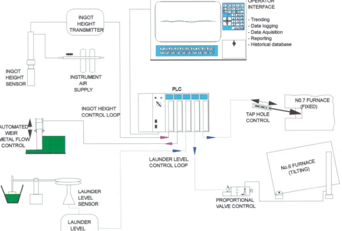
The objective of the project was to accurately and consistently control the quantity of aluminium supplied to each mould during the ingot casting process, from the No.6 tilting furnace and the No.7 fixed furnace to No. 1 ingot casting machine, see Fig. 1.
The project consisted of three stages,
3.1 Stage 1
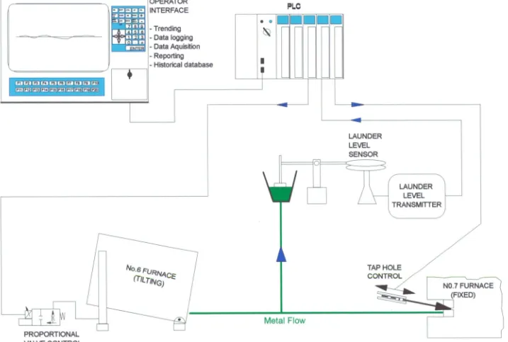
The aim was to control the No.6 furnace tilt from the full to empty state with the absolute minimum launder level variation for the entire cast, in order to achieve a consistent flow rate, see Fig.2.
3.2 Stage 2
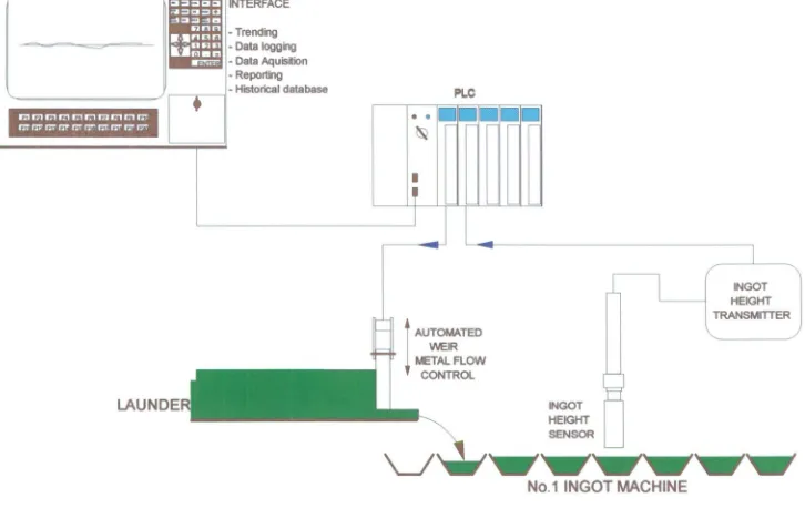
The aim was to utilise an ingot height measurement system to automate the actuation of the weir based on feedback of the ingot height, and to gain an understanding of the process, see Fig.3.
3.3 Stage 3
INGOT HEIGHT SENSOR
INSTRUMENT AIR SUPPLY
INGOT HEIGHT TRANSMITTE
INGOT HEIGHT CONTROL LOOP
AUTOMATEDA WEIR I METAL FLO
CONTROL
LAUNDER
LEVEL — SENSOR
ra 121 LAI IA Id
14L1141, 14F: an 141- 141,:141.141: 1411'
•
•
NO.7 FURNACED(ED) TAP HOLE
CONTROL
PROPORTIONAL VALVE CONTROL
1:1==C112 f-41= -11:11=—'111R
ri pi!.rir1ri
I
i
'ra l ow riETV:37
-
OPERATOR INTERFACE
- Trending - Data logging - Data Aquisition - Reporting
- Historical database
PLC
N
LAUNDER LEVEL CONTROL LOOP
(—LAUNDER
LEVEL
[image:13.834.43.745.29.503.2]',-RANSMITTER
ommuo Fa=cumu onn glinnn aim
Iv=
• 0
1'
m
MEM
OPERATOR INTERFACE
- Trending - Data logging - Data Aquisition - Reporting
- Historical database
La La La ta to LLA ra La LE LEEI 13E1 EIFI 11:1 110 t;E:1 Cif/ MI [E1
PLO
\to/
LAUNDER LEVEL SENSOR
0
LAUNDER LEVEL TRANSMITTER
Metal Flow
TAP HOLE CONTROL
-Ng libbs NO.7 FURNACE
(FIXED)
[image:14.835.34.751.35.518.2]PROPORTIONAL VALVE CONTROL
rill mi. 17117.1 FA 171 17/ 171 ri 17;
rar 137 rir ralr mrrr rrri
1:11=I=CICI r-A=1:1=C2
s-3 rm !limn ri
Fl
IOLA rl
N1-77M7
OPERATOR INTERFACE
- Trending - Data logging - Data Aquisition - Reporting
- Historical database PLC
•
•
Elm
li
INGOT HEIGHT TRANSMITTERI
AUTOMATEDWEIR METAL FLOW
CONTROL
LAUNDE
INGOTHEIGHT SENSOR
...'swiswIormirloPrwir
[image:15.834.36.762.20.478.2]No.1 INGOT MACHINE
Page 8
4.0 BENEFITS
The benefits of the control system are as follows :
4.1 Financial
Prior to installation of the ingot height control system, 10% of 22-kg ingot produced was out of specification (London Metal Exchange, LME) physically.
With 53 597 tonnes of 22-kg ingot production planned for 1992-93 this equates to 5360 tonnes of metal which can not be offered on the LME.
The out of specification ingot produced year to date (y.t.d.) is 0.49% out of the No.6 Furnace and 1.7% out of the No.7 Furnace. Resulting in a payback period of less than 6 months.
4.2 Safety (Launder Overflow Prevention)
Metal spill from the No.6 furnace or launder arrangement could be detrimental to 22-kg ingot production. Due to the close proximity of control panels (for furnace and ingot casting machine), it is necessary to ensure that metal spill from ingot production does not occur. With the launder monitoring system currently installed there has been no metal overflows from this facility.
Page 9
4.3 Future
With the function of real time displays (trending, histograms, etc.) and data capture a basic understanding of the process can now be attained, evaluated and a course of action taken to further improve the system.
The system, now that it has been developed and proven, is being utilised at other casting facilities within Metal Products.
Modifying the No.7 Tap hole so that the plug remains submerged would ensure that the freezing of the tap hole does not occur, ensuring a consistent and predictable flow of metal.
4.4 General
Now that a more consistent ingot is obtained, tolerances within the robot stacking system have been minimised to obtain tighter packed bundles. The benefit being, bundles when strapped remain tight when transported, thereby reducing the existing problems of loose strapping.
With metal flow control the cast rate is more steady, as flow fluctuations from the furnace have been minimised from the furnace full to empty state.
a) improve casting speed
b) improve (minimise) operator control c) fewer reject ingots,
d) tighter packed bundles, that will maintain their stability throughout transportation,
Page 10 A short explanation of each benefit:
a) Improve casting speed
The options when the furnace was less than half full and the metal flow rate begins to reduce, was to slow the casting conveyor accordingly or increase operator control of the furnace tilt as the cast continues. The results being, a slower cast rate or more metal flow fluctuations and larger ingot variance.
With launder level control the cast speed can be maintained at a fixed rate with minimal flow fluctuations.
b) Improve (minimise) operator control
On completion of stage 1, the operator no longer controls the furnace tilt, and operation of the weir once set can be left alone. This results in a regulated flow of metal for the entire cast, leaving the only control required by the operator, is minimal belt speed variation.
On completion of stage 2 once the cast is underway, minimal operator control is required i.e. the system is a closed loop whereby the system will "tune" itself automatically to maintain a fixed ingot height.
c) Fewer reject ingots,
Bringing the system under control as mentioned above, improves the dimensional uniformity of each ingot.
d) Tighter packed bundles,
Page 11
The result being, that bundles when strapped will remain tight when transported, thereby reducing the problems of loose strapping.
e) Safety (launder overflow prevention)
The design is such that if the launder level were to exceed a preset setpoint, the output to the hydraulic proportional valve is zero (4 mA), thereby disabling the furnace tilt. If the launder level sensor fails, there is a high level proximity switch on the sensor mechanism which detects an abnormally high level in the launder causing the hydraulics to be disabled from tilting further, whether the system is in automatic or manual. The high level proximity switch will override all tilting actions when it is "made". This minimises the possibility of metal spill from the launder, previously no such safety feature was installed.
0 Gain an understanding of the process
Page 12
5.0 SCOPE
5.1 Stage 1
- Install a weir in the launder - Install launder level control - Weir actuation to be by operator
Crucial to achieving good ingot consistency is the maintenance of a consistent head of metal behind a weir in the launder.
Installation of a weir also has the benefits of allowing the furnace tilt and launder level control to be a closed loop i.e. not acted upon by the operator and the cast speed to be maintained. Currently the cast speed is reduced near the end of a cast as metal flow decreases i.e. it is easier to control the belt speed than the furnace tilt to maintain ingot consistency.
The furnace tilt is governed by the launder level (irrespective of the weir position). Once a constant launder level is obtained and the weir position set for a fixed flow, only minor cast belt speed adjustments at the start of the cast need to be made by the operator to obtain the desired ingot size, see Fig.2.
5.2 Stage 2
- Install ingot height measurement system - Automate weir or belt speed control
Page 13
The ingot height information is also used in the feedback loop to automatically control the actuation according to ingot height. The system will then be a closed loop, (i.e. system actions will be met with system reactions) requiring minimal operator interaction.
5.3 Stage 3
- Install new tap hole flow control device in No.7 furnace.
The liquid metal flow to the casting machine is controlled by a motorised regulating bar assembly, see Fig.2.
To ensure accurate control over the full range of metal flow, a special refactory tap-out block with a replaceable nozzle insert is incorporated into the furnace refractory lining.
The control device mounting bracket is attached to the side of the launder casing and incorporates the following:
- regulating bar guide system - activating lever assembly
- manual emergency override lever - electric actuator
The regulating bar assembly consists of an adjustable round bar with a graphite cone fitted to the lower end to enable control of the metal flow. A counterweight is fitted to the top end to ensure accurate positioning during the operation.
To ensure good sealing of the furnace tap hole nozzle when not casting, a separate manual stop bar assembly is used. A ceramic fibre cone is fitted over the graphite plug on the stop bar assembly.
Page 14
6.0 CASTING SYSTEM OVERVIEW
6.1 Launder Level Control
6.1.1 Furnace Tilt Control
The discharge of molten aluminium from the furnace must be regulated in order to maintain a constant flow to the casting belt.
The furnace tilt is controlled by means of a feedback loop from a capacitance sensor in the discharge launder. The capacitor sensor indicates the metal level to the PLC. The PLC using this input signal, actuates a proportional valve which controls the supply of hydraulic fluid to the lifting rams. Fluid is supplied to the rams until the metal reaches the desired launder level setpoint, where upon the flow is inhibited.
This is a PID controller designed to maintain a constant head of metal in the discharge launder.
6.1.2 Molten Metal Flow
Despite maintaining a fixed head of metal in the launder, flow fluctuations from the furnace do occur when tilting. A secondary flow control device regulates this flow of metal from the launder into the tundish.
Page 15
6.2 Ingot Height Measurement Control System
6.2.1 Molten Metal Height Detection
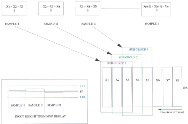
Molten metal height in each mould is measured by a capacitance level sensor positioned above the moving casting belt, and close to the skimming operator. As the mould position in the belt can vary vertically the metal height is expressed relative to a reference point on that mould i.e. the mould hinge. As the moulds are continuously moving under the capacitive sensor a snap shot of the height of the mould hinge is taken when it is directly under the sensor. Similarly the level of the molten metal at the centre of the mould is achieved by taking a snap shot. With a fixed ingot mould size, and subtracting the height of the metal from the height of the hinge a corresponding ingot height is achieved. The ingot height is averaged for a sub group size of 3 moulds (selectable 1-4). A point, representing the running sub-group average of the last 3 ingots, is then automatically plotted on a VDU trend display.
Page 16
7.0 PROCESS CONTROL INSTRUMENTATION AND MECHANISMS
The development of this project comprised 3 stages:
7.1 Stage 1 (Furnace tilt control loop)
Development of PLC Software for Furnace No.6 Launder Level
Control
The program developed controls all actions of the tilting furnace from temperature to doors and primarily an automatic/manual tilt control. The tilt automatic tilt control is basically a PID loop, the process variable being the actual launder level the setpoint determined by the operator and the output the signal to the hydraulic proportional valve
Installation of:-
7.1.1 Retrofit Of PLC 2 to PLC 5
The Allen Bradley PLC 2 utilised on the furnace was unsuitable for the proposed application due its limited maths capabilities (no PID or floating point maths facilities) and poor networking and programming features, and was therefore replaced completely utilising an Allen Bradley PLC5 controller
7.1.2 Hydraulic Proportional Valve Controller
Level
N
ProbeMetal Level
Frequency
411.•
Page 17
[image:25.565.36.504.65.329.2]Electronic Insert
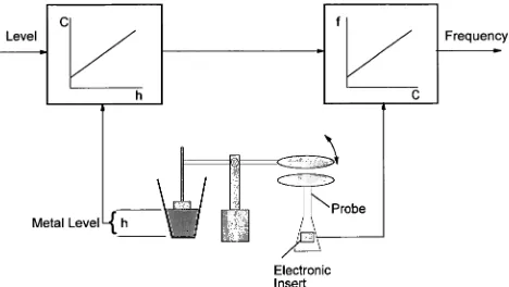
Figure 4. Capacitive Launder Metal Level Measurement
Level Frequency
INGOT HEIGHT SENSOR
Metal Level
[image:25.565.36.501.74.743.2]No.1 INGOT MACHINE
Page 18
7.1.3 Launder Level Sensor
The Launder level sensor comprises of a capacitive sensor (Endress & Hauser) with a large disc fitted to a probe, and fixed permanently to the launder steelwork. A float, pivot arm and steel disc make up the moving section of the sensor. As the launder level increases the gap between the two steel plates decreases and the capacitance increases. An insert within the probe converts the signal from capacitance to frequency. A separate controller converts this frequency to 4-20mA signal corresponding to the launder height. Scaling of the launder level is carried out within the PID instruction.
7.1.4 Operator Controlled Weir Via a Motorised (Variable Speed)
Drive
A variable speed drive (Allen Bradley) in association with a 3 phase, 415V, 0.75kW motor and 15:1 gearbox ratio is used as the actuator for the weir. The weir actuation for fast, slow, raise and lower presets are setup within the variable speed drive. All control commands (Fast, Slow, Raise and Lower) are directed through the PLC and then output to the variable speed drive.
7.2 Stage 2 (Ingot height control loop)
7.2.1 Installation of Ingot Height Sensor.
Page 19
capacitor. The sensor being the other plate. Any change in level would appear to the sensor as a change in distance between the plates. The resultant change of capacitance will vary the frequency of a variable oscillator located in the pre-amplifier in the rear of the sensor. The frequency signal is transmitted to the converter and converted to a voltage. Within the recommended ranges the output voltage (or current) will be linear and proportional to the distance changes. The sensor measuring plate is guarded to prevent false signals from other objects or surfaces not in the desired sensing area.
7.2.2 Development of PLC Software for Ingot Height Measurement
and Automated Weir Control
J
TOP OF INGOT MOULD
INCREASING OUTPUT FROM SENSOR
INGOT HEIGHT SENSOR
aMijur
INGOT METAL LEVELDIRECTION OF INGOT TRAVEL
SENSOR HEAD (Maximum Value
INGOT SIZE = c - (b-a)
Fig.6 Real Time Display of Sensor Output
SP LCL SAMPLE 1 SAMPLE 2 SAMPLE 3
INGOT HEIGHT TRENDING DISPLAY
SUB-GROUP 3
S . GROLTP 2
GROI 1
X2 X3 X4 X5 X6
INGOTS
Direction of Travel
SI
X1 X7 X8
X1 + X2 + X3 X2+ X3+ X4 X3+X4+X5 X(n-2) + X(n-1) + Xn
3 3 3 3
[image:29.835.56.691.47.465.2]SAMPLE 1 SAMPLE 2 SAMPLE 3 SAMPLE n
Page 22
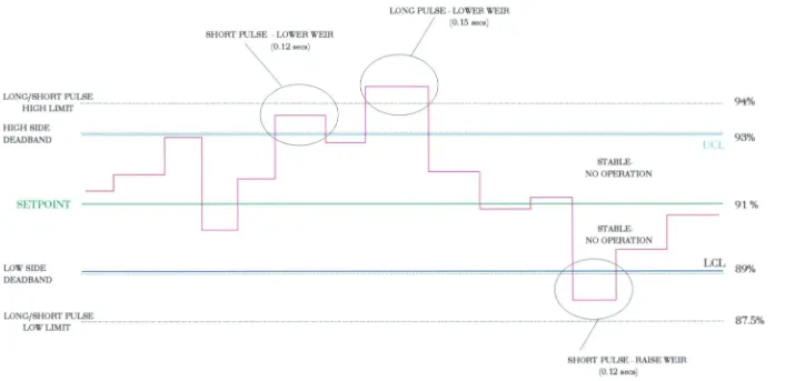
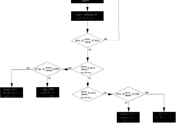
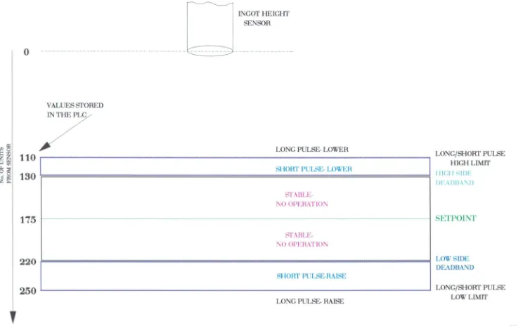
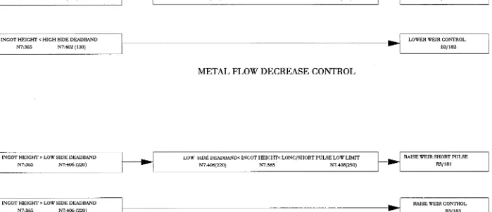
called for the weir to raise/lower the consequences of this action (in terms of increased/decreased metal flow) will only be seen by the sensor some 30 seconds later, the system will then measure the height of the next two sub-groups i.e. another 12 seconds, the result is a delay of 42 seconds before the system will make a change to the weir position again. Once the sub-group average height has been determined it is compared with the ingot height setpoint (80mm or 91% of mould capacity) see Figs. 8, 9 & 10. There is a deadband around the setoint of 2% , where there is no action taken by the system. If the process variable PV (ingot height) is 93%<PV<94% for longer than 50 seconds the weir will be lowered down for a .12 second pulse, If the PV>94% for 50 seconds the weir is lowered down for a pulse of .14 seconds. If the process variable PV (ingot height) is 87.5%<PV<89% for longer than 50 seconds the weir will be raised up for a .12 second pulse. If the PV<87.5% for 50 seconds the weir is raised up for a pulse of .14 seconds, see Fig.11 & 12.
An improvement to the system would be to relocate the sensor adjacent to the tundish to minimise delays in the system.
LONG PULSE - LOWER WEIR
SHORT PULSE - LOWER WEIR
(0.12 secs)
(0.15 secs)
LONG/SHORT PULSE
94%
HIGH LIMIT
HIGH SIDE ... _ ...
93%
DEADBAND N
STABLE- NO OPERATION
91%
SETPOINT
STABLE- NO OPERATION
LOW SIDE ... LCL 89%
DEADBAND
LONG/SHORT PULSE
LOW LIMIT - 87.5%
SHORT PULSE - RAISE WEIR
[image:31.834.45.751.59.402.2](0.12 secs)
0
INGOT HEIGHT SENSOR
VALUES STORED IN THE PLC
LONG PULSE- LOWER
110
LONG/SHORT PULSE HIGH LIMITI IIGI I SIDI,: DFADBAN
SETPOINT
LOW SIDE DEADBAND
LONG/SHORT PULSE LOW LIMIT
130
175
220
250
SHORT PULSE- LOWER
STABLE- NO OPERATION
STABLE- NO OPERATION
SHORT PULSE-RAISE
[image:33.834.40.794.41.505.2]LONG PULSE- RAISE
INGOT HEIGHT SENSOR
100
LONG PULSE- LOWER
LONG/SHORT PULSE HIGH LIMIT (N7:404)
SHORT PULSE- LOWER LONG/SHORT PULSE DISCRIMINATION RANGE (N7:403)
130---- .... HIGH SIDE DEADBAND VALUE (N7:402)
STABLE-
HIGH SIDE DEADBAND RANGE (N7:401) NO OPERATION
175
SETPOINT (N7:400)STABLE-
NO OPERATION HIGH SIDE DEADBAND RANGE (N7:405)
SHORT PULSE- RAISE LONG/SHORT PULSE DISCRIMINATION RANGE (N7:407)
V LONG/SHORT PULSE
250-
LOW LIMIT (N7:408)LONG PULSE- RAISE
INGOT HEIGHT > LOW SIDE DEADBAND N7365 N7406 (220)
LOW SIDE DEADBAND< INGOT HEIGHT< LONG/SHORT PULSE LOW LIMIT N7406(220) N7:365 N7408(250) INGOT HEIGHT < HIGH SIDE DEADBAND
N7365 N7:402 (130)
HIGH SIDE DEADBAND> INGOT HEIGHT> LONG/SHORT PULSE HIGH LIMIT N7:402(130) N7365 N7404(110)
LOWER WEIR SHORT PULSE B3/180 INGOT HEIGHT < HIGH SIDE DEADBAND LOWER WEIR CONTROL
N7365 N7:402 (130) B3/182
METAL FLOW DECREASE CONTROL
RAISE WEIR SHORT PULSE B3/181 INGOT HEIGHT > LOW SIDE DEADBAND
N7365 N7406 (220)
RAISE WEIR CONTROL B3/183
[image:35.835.66.765.81.383.2]METAL FLOW INCREASE CONTROL
Page 28
7.3 Stage 3 (Furnace tap-hole control loop)
Development of PLC Software for Furnace No.7 Tap Hole and
Launder Level Control.
Utilising the launder level control system sensor, developed in stage 1. The electric actuator installed relies on pulse duration to determine how far the tap hole plug is moved into or out of the tap hole, 2 contacts determine in which direction the actuator operates. The same control philosophy as stage 2 is utilised, whereby the launder level process variable is compared to the launder level setpoint, and depending on the error between the two determines the movement of the actuator. A recognised problem with this facility is the location of the tap hole relative to the launder, the tap hole is above the metal level in the launder where it is prone to freezing of the metal. Such freezing causes non repeatability in the system, the result is an improved metal flow but not consistent enough to maintain metal levels to the accuracy of the tilting furnace. An improvement to the system would be to locate the tap hole so that it is submerged in the launder metal, the graphite material of the tap plug lends itself to this type of application.
7.4 Stage 4 (Data integration - Under Investigation)
Full integration of software with Metal Products proposed data aquisition/supervisory control system, to provide multiple user access to historical data for statistical analysis.
Page 29
8.0 SOFTWARE DEVELOPMENT
8.1 Stage 1 Launder Level Control Software Development
To enable the technical evaluation of the launder level sensor to proceed and to identify how it may be best utilised, it is necessary to develop PLC and computer software capable of capturing the sensor data and to perform basic statistical calculations and display functions. See Files 4,7,8 PLC program listing.
8.2 Stage 2 Ingot Height Control Software Development
The second stage of software development allows for full automation of the metal flow i.e. launder and ingot height control, see Files 8,10,12 PLC program listing.
Also available is the facility for operator and supervisor access. It is envisaged that provision be made for the operator to key in the cast number and for data acquisition to be automatic once molten metal appears in the moulds (Metcon System).
The software provides the supervisor/operator with an option to view a whole cast at the completion that cast. This will provide instant feedback of the systems ability to control ingot size, see File 13 PLC program listing.
All data storage and display options are accessed from a keyboard via an industrial computer. Data may be backed up and archived to floppy disk, or printed for later analysis.
8. 3 Stage 3 Furnace Tap Hole Control Software Development
Page 30
8.4 Stage 4 Data Integration Software Development
The final stage of software development will be to fully integrate the control system with the Metal Products Data Aquisition/Supervisory Control system.
Data may be backed up and archived on a VAX providing the facility of data retrieval and display from all terminals connected to the network.
The facility of integrating the cast information to Metcon (if this facility is required) is currently under investigation.
9.0 INGOT HEIGHT SENSING
9.1 Description
Molten metal height in each mould is measured by a capacitance level sensor positioned above the casting conveyor. As the mould position in the conveyor can vary vertically the metal height is expressed relative to a reference point on that mould i.e. the edge of the mould. The metal height is averaged over a sub-group size of the last three moulds. The latest sub-group value is then plotted on the ingot height trend chart.
Page 31
9.2 Principle of Sensor Operation
A Delavan Hot Prox 620 model CNR 200 is used to measure the
molten metal level in the moulds. It is a capacitance sensor, designed
to measure changes of capacitance to earth as they occur. The
molten metal surface and the mould edge act as earthed plates similar
to one plate in a parallel plate capacitor. The sensor being the other
plate. Any change in level would appear to the sensor as a change in
distance between the plates. The resultant change of capacitance will
vary the frequency of a variable oscillator located in the
pre-amplifier in the rear of the sensor. The frequency signal is
transmitted to the converter and converted to a voltage. Within the
recommended ranges the output voltage (or current) will be linear
and proportional to the distance changes. The sensor measuring plate
is guarded to prevent false signals from other objects or surfaces not
in the desired sensing area.
9.3 Sensor Output
A maximum and minimum is associated with each ingot measured.
For Control purposes in the software the maximum represents the
surface furthermost away from the sensor (the molten metal surface),
the minimum represents the closest surface (the mould edge).
Page 32
10.0 INSTALLATION & OPERATION OF SENSOR &TRANSMITTER
10.1 Specifications
Input Voltage
Power/Frequency
Operating Temperature:
Cooling Sensor:
Output Signal:
Time Response:
Cable Length:
System Drift:
Measured Drift:
Measuring Range: Sensor Size: Maximum Range: Stability:
Deviation:
240 VAC Nominal
10 Watts, 50 Hz
Transmitter +5°C to 50°C
+ 94°C Maximum (pre-amp), forced air of instrument quality required. Requirements vary but supply must be adequate to maintain internal temperature below 94°C
0-10 VDC (optional -5V to +5V and 4-20mA)
1 millisecond to 1000 milliseconds in 4 steps
6 metres, 6 conductor 150°C service temp
100 minutes from room temperature to full heat 800°C process
+ 0.00127 mm/hour
50.8 mm 178 mm
Page 33
10.2 Mechanical and Electrical Installation
Sensor Mounting:
10.2.1 The CNR Sensor uses 1-1/2" Pipe for mounting. This pipe is used to conduct air cooling to the sensor as well as contain the sensor cable.
10.2.2 Fasten the cable connector to the pre-amp by rotating the knurled fitting clockwise. (Note: That the connector has a keyway locater.) This connection should be finger tight, do not use a tool.
10.2.3 Connect Black wire from cable to internal ground lug located in 1-1/2" nipple.
10.3 Air Cooling Sensor:
Where the sensor is located it is exposed to elevated
temperatures and it must be cooled by purging with air. Maximum pre-amplifier temperature is (94°C).
10.4 Temperature Sensor
Page 34
11.0 SENSOR ARM
There are two major actions in the sensor arm designed, as safety features to prevent sensor damage.
11.1 The first is a hinge pin and bracket in the vertical plane. This allows the sensor to be swung to the conveyor side during maintenance.
11.2 The second consists of a pivot plate, which allows the sensor to pivot when contact is made. The sensor can only pivot in the same vertical plane as the direction of the casting conveyor. Once the obstruction has passed the sensor will pivot back to its original
position automatically.
The sensor (pre-amplifier) cannot be exposed to temperatures in excess of 95°C. To ensure the sensor temperature is maintained below this level, compressed air of instrument quality is forced into the sensor arm and hence through the sensor thereby cooling it.
The braided tube is the air line.
The Anaconda conduit contains the sensor- transmitter cable.
Page 35
12.0 OPERATION
This section contains the calibration information for the Hot Prox/620 system utilising the CR185 transmitter and the CNR 200 sensor.
12.1 Calibration /General
The controller outputs consist of 4-20mA loop, and a 0-10 volt or -5 to +5 volt output. All of these may have a positive slope called "Normal," or a negative slope called "Reverse." The output used on the Ingot Height Sensor is "Reverse." The Controller output utilised is 0-10 volts.
12.2 Calibration/Reverse Operation:
An increase in capacitance causes an increase in voltage (or current), i.e. a reduction in distance between sensor and subject causes an increase in output.
12.2.1 Set output switch to reverse position.
12.2.2 For voltage output instead of current, set "volts range"
jumper to 0-10 volts or -5 to +5 volts as needed. The 4-20mA output is always energised.
12.2.3 Using a small screwdriver, set controls as follows:
OFFSET: OFFSET Switch to ZERO Position SPAN: All Switches CLOSED
Page 36
12.2.4 Unlock OFFSET and SPAN potentiometers located on panel
face by moving the small lever on each potentiometer counter clockwise to WHITE dot. Turn both potentiometers fully clockwise.
12.2.5 Set the shortest desired distance, ground-plane to sensor.
Monitor 0-10 volts output:
A) Output is LESS than 10 Volts.
Set "OFFSET" switch to "POSITIVE."
B) Output is GREATER than 10 Volts.
Turn "OFFSET" potentiometer counter-clockwise until output equals 10 volts. Lock "OFFSET" potentiometer by moving lever to RED dot.
12.2.6 Set the longest desired distance, ground-plane to sensor.
Monitor 0-10 volts output:
A) Output is GREATER than 0 Volts.
Increase total number of open "SPAN" switches, one at a time until output is LESS than 0 volts.
Page 37
B) Output is LESS than 0 Volts.
Turn "SPAN" potentiometer counter-clockwise until output voltage equals 0 Volts. Lock SPAN potentiometer by moving
lever to RED dot.
12.2.7 Basic calibration is now complete. To set the response time,
go to step 11.2.8.
12.2.8 A) Voltage (or current) output appears jittery or responds too
fast:
Increase response time by closing switches 2 through 4 until output is steady.
B) Voltage (or current) output appears sluggish or slow to respond :
Decrease response time by opening switches 4 through 1 until output is responsive.
Page 38
13.0 MAINTENANCE & SERVICE
13.1
Two Year Product Warranty:
Delavan Electronics, will replace, put in good operating condition, or purchase price refunded, at the option of DELAVAN, free of charges except transportation if defective in their manufacture or shipping, and if notice of said defect is received by Delevan within two years of shipment date.
NOTE: The location of the sensor is in an area where excessive temperatures are attainable, therefore it is necessary to ensure that the sensor is always receiving cooling air over the pre-amp. Because this is a variable not controlled by Delavan, the sensor warranty is limited. Each sensor pre-amp is marked with a temperature sensitive paint so that an individual unit can be examined to determine the exact temperature exposure. Preamp units that have experienced temperatures above 94°C will not be repaired under warranty.
Supplied locally by:
Sencon Pty. Ltd. 18 Innocent St Kings Meadows
Telephone: 447 433
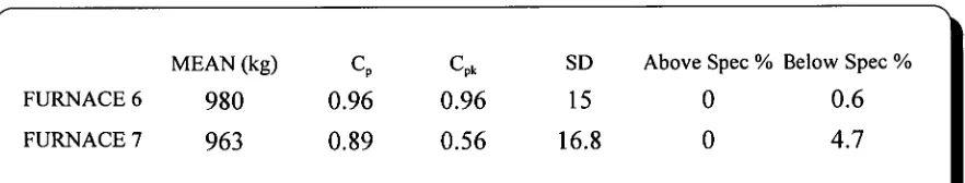
14.0 RESULTS
c
MEAN (kg) Cp Cpk SD Above Spec % Below Spec % FURNACE 6 949 0.66 0.21 22.8 0.33 27.33
FURNACE 7 939 0.54 0.05 27.5 0.29 43.43
\
PRIOR TO INSTALLATION OF INGOT HEIGHT CONTROL SYSTEM
c
MEAN (kg) Cp Cpk SD Above Spec % Below Spec %
FURNACE 6 980 0.96 0.96 15 0 0.6
[image:47.565.55.496.369.453.2]FURNACE 7 963 0.89 0.56 16.8 0 4.7
I
INGOT HEIGHT CONTROL SYSTEM INSTALLEDDate Mean Cp Cpk SD Above
Spec % Spec % Below 15-30 Sep 92 977.4 0.51 0.48 29.7 4.31 5.69 20-30 Nov 92 943.7 0.58 0.11 25.9 0.31 36 1-31 Dec 92 967.1 0.8 0.57 18.8 0 5.48 14-16 Jan 93 974.5 0.79 0.7 18.9 0 2.36 24-26 Jan 93 973.2 0.8 0.68 18.7 0 2.73 10-12 Feb 93 965 0.73 0.49 20.6 0 9.09 21-24 Mar 93 971.2 0.78 0.62 19.3 0 3.79
Overall - Furnaces 6 & 7
Date Mean Cp Cpk SD Above Spec %
Below Spec % 15-30 Sep 92 975.2 0.66 0.59 22.8 1.48 2.96 20-30 Nov 92 949.1 0.66 0.21 22.8 0.33 27.33 1-31 Dec 92 973.2 0.94 0.79 16 0 2.56 14-16 Jan 93 982.9 0.95 0.89 15.8 0 0.59 24-26 Jan 93 980.3 0.96 0.96 15.6 0 0.59 10-12 Feb 93 973.5 0.93 0.79 16.1 0 2.34 21-24 Mar 93 976.7 0.91 0.84 16.6 0 0.72
Furnace No.6
Date Mean Cp Cpk SD Above Spec %
Below Spec % 15-30 Sep 92 979.9 0.45 0.45 33.6 6.49 7.3 20-30 Nov 92 939.1 0.54 0.05 27.5 0.29 43.43 1-31 Dec 92 945.4 0.71 0.16 21.1 0 30.16 14-16 Jan 93 963.3 0.89 0.56 16.8 0 4.72 24-26 Jan 93 963.5 0.82 0.52 18.2 0 5.65 10-12 Feb 93 955.4 0.72 0.33 20.8 0 16.67 21-24 Mar 93 962.1 0.74 0.45 20.1 0 8.82
Furnace No.7
London Metal Exchange Weight Tolerance Variation Data Analysis 25kg Ingot Bundle Weights
[image:48.565.91.484.79.208.2]Launder Level Control Commissioned 1/12/92 Ingot Height Control Commissioned 11/1/93 Furnace Tap Hole Control Commissioned 11/1/93
■•••••••••••••
-
INGOT UEIGHT USING AUTO CONTROL
ile :22AUTO Date:12-16-1992, 09:47:08 Dmpany :COMALCO (BELL BAY) LIMITED
].ant :BELL BAY Part name :NO.6 FURNACE apartment :METAL PRODUCTS Part Numbers :DAY SHIFT CASTS whine :NO.1 M/C Sample frequency:EACH
Deration :ROBOT WEIGHING Units :KG laracteristic :INGOT WEIGHT USING AUTO CONTROL
Descriptive Statistics All (n=1)
117 data points
Interval = mid-point
7.0 Mean = 973.2 Min. Value = 925 Chi Squared= 3.384 Sigma Indiv= 16.0 Max. Value = 1008 deg. free. = 5 Est. Sigma = 10.4 Kurtosis = 0.041 Conf. Level= 95% Coeff.Var. = 0.0 Skewness = -0.352 Normal
Capability
Using Sigma Indiv
Actual % Theoretical %
Above Spec = 0.00 Upper Spec.= 1025.0 Above Spec = 0.06 Below Spec = 2.56 Nominal = 980.0 Below Spec = 0.86 Out of Spec= 2.56 Lower Spec.= 935.0 Out of Spec= 0.92 Cpk = 0.79 Cr = 1.07 Z upper = 3.23 Cp = 0.94 Z lower = 2.38 Mean + 3s = 1021.4
Mean - 3s = 925.1
± .1=r .gr 1---
Ii
§
6 6 6 6 6 6 6 6 6 6 6 6
INGOT WEIGHT NO. 6 FURNACE
lie ompany lant
epartment achine peration
haracteristic
:INGOT25 :PQ Systems :BELL BAY
:Metal Products :N0.1 M/C
:Robot Weighing
:INGOT WEIGHT No.6 Furnace
Descriptive Statistics
Date:02-15-1993, 10:30:06 Part name
Part Numbers
Sample frequency: each Units :kg
1-169(n=1) 169 data points
Interval = lower boundary
6.0 Mean = 980.3 Min. Value = 933 Chi Squared= 6.559 Sigma Indiv= 15.6 Max. Value = 1018 deg. free. = 7 Est. Sigma = 9.9 Kurtosis = 0.055 Conf. Level= 95% Coeff.Var. = 0.0 Skewness = -0.070 Normal
Capability
Using Sigma Indiv
Actual % Theoretical %
Above Spec = 0.00 Upper Spec.= 1025.0 Above Spec = 0.21 Below Spec = 0.59 Nominal 980.0 Below Spec = 0.18 Out of Spec= 0.59 Lower Spec.= 935.0 Out of Spec= 0.39 Cpk 0.96 Cr 1.04 Z upper = 2.87
Cp 0.96 Z lower = 2.91
Mean + 3s 1027.0 Mean - 3s 933.6
I-I -t: .=4 r--
U
N
-I
6 9 4 4 6
g
.
5
9
5 6 6
9 2 6 6
9 7 4 6
9
6 9
9 2 6
9 9
6 4 6
6 6
10
6 6
3
6
21C2 20C1
14C1
Figure 5
15C2 18C1
DATE
12C2
1 1C3 cAST 3
tit
INGOT BUNDLE WEIGHT VARIATION
X BAR CONTROL CHART - JUNE 1993
TARGET WEIGHT = 980kg
1025
1015
1005
995
E-( 985
1--1 975
965
955
945
935
. .
114E Upper Weight Limit 1020k-g
— ---
LME Lower Weig,ht Limit- 9-+Okg
[image:51.837.82.754.42.501.2]15.0 CONCLUSION
AUTO;
0 MANUAL
U
.
24 VAC
INGOT HEIGHT CONTROL SYSTEM
LAUNDER LEVEL MAX PROX
LAUNDER LEVEL MIN. PROX /*
RACK 0 MODULE GROUP 2 1:02/00
•
1:02/01
•
•
11
WEIALOPEN MAihPROX 1.02/020
---
WEIOPEN MINA,PROX
0 W ---1.
-
0 0
I:02/03•
IWEIR RAISE
0 • • 0
1.02/040
WEIR LOWER
0 •
1.02/050
•
I:02/06•
•
•
1.02/07•
FAST 'WEIR SPEED
S•
SLOW II
•
•
DRIVE RUNNING•
DRIVE FAULT•
•• 1.02/11 1.09110•
WEIR ACTUATION
•
•
1.02/120-6 1:02/13
•
•
o 7 TAP PLUG IN
No 7 TAP PLUG OUT
• I:02/14
•
1:02/15
•
o7 TAP PLUG IN• 1:02/16 No 7 TAP PLUG OUT
• 1.02/17
•
NEUTRAL
TERMINAL INDEX
No.2 Ingot Machine Panel Junction Box 1
No 7 TAP PLUG OUT
No.1/2 INGOT MACHINE
Spare
24 VAC
INGOT HEIGHT CONTROL SYSTEM
RACK 0 MODULE GROUP 3 No. 7 FURNACE AUTOMATIC
• •
1:03/00
No 7 TAP PLUG IN
•
Spare
• 1:03/01
1:03/02
1:03/03
•
•
•
•
•
I:03/04• 1:03/06
1.03/07
•
•
Spare
Spare
Spare
Spare
Spare
Spare
Spare
Spare
1.03/10
1:03/11
1:03/12
I:03/13
1:03/14
1:03/15
1:03/16
1:03/17
•
•
•
•
•
•
•
•
•
•
•
•
•
•
TERMINAL INDEX
•
No.7 Furnace Control Panel 0 Ingot Machine Junction Box 2NEUTRAL
RACK 0
INGOT HEIGHT CONTROL SYSTEM
240 VAC 10 0 . AUTOMATIC LEVEL CONTR.(
0
0 0:05/00
0 0:05/01 0
... .
MAX. LAUNDER LEVEL
iv
__
0:05/02 0 00
0 \ MIN. LAUNDER LEVEL
0
0 0:05/03 0
o.7 TAP PLUG IN ACTUATOR
0 0:05/04 0 • 0
o.7 TAP PLUG OUT ACTUATC
No.7 TAP PLUG IN
0 0:05/06
•
II
0
No.7 TAP PLUG OUT
0.05/ 1 0 spare
0
•
0:05/11 Spare
0 •
0 0:05/12 0 spare TERMINAL INDEX
II
No.7 Furnace Control Panel 0 0:05/13 0 Spare 0 No.1 Ingot Machine Panel0
0:05/14 Spare 0 PLC Panel •0 0:05/15 Spare •
0 0:05/16 spare • 0:05/17 spare
0 •
S
COMMONI
COMMONS
COMMONV.SPEED DRIVE SLOW RAISE
V. SPEED DRIVE SLOW LOWER
#
i
•
V.SPEED DRIVE FAST RAISE
V. SPEED DRIVE FAST LOWER
I
I
V. SPEED DRIVE ON
RACK 2
INGOT HEIGHT CONTROL SYSTEM
MODULE GROUP 6
TERMINAL INDEX
0
Metal Flow Control Panel 0 PLC Panel0:26/00
0:26/01
0:26/02
0:26/03
0:26/04
INGOT HEIGHT CONTROL
PLC/Citect Address', Descriptors & Values
N7:400 Ingot Height Setpoint 175
N7:401 Ingot Height High Side Deadband Range 45
N7:402 Ingot Height High Side Deadband Value 130
N7:403 Long/Short Pulse Discrimination (High Side) Range 30
N7:404 Long/Short Pulse High Side Value 100
N7:405 Ingot Height Lowside Deadband Range -45
N7:406 Ingot Height Lowside Deadband Value 220
N7:407 Long/Short Pulse Discrimination (Low Side) Range -30
N7:408 Long/Short Pulse Low Side Value 250
N7:410 Raise Weir Short Pulse Time 12
N7:411 Raise Weir Long Pulse Time 14
N7:412 Lower Weir Short Pulse Time 12
N7:413 Lower Weir Long Pulse Time 14
T4:35 Increase Ingot Height OFF Delay Control 55
T4:36 Raise Weir Pulse Timer Variable
T4:37 Decrease Ingot Height OFF Delay Control 55
CITECT ADDRESS'
Launder Level Setpoint N20:10
Raw Zero :0 Engineering Zero :0
Launder Level Height PV N20:11
Raw Zero :0 Engineering Zero :65
Furnace Proportional Valve 20:12
(PLC VALUE : Variable 0-700)
Raw Full Scale :700 Engineering Full Scale:100mm
(PLC VALUE: 525)
Raw Full Scale :700 Engineering Full Scale:100mm
(PLC VALUE: 570)
Raw Full Scale :700 Engineering Full Scale:100mm
(PLC VALUE : 480)
Raw Full Scale :700 Engineering Full Scale: 100m
(PLC VALUE: 500)
Raw Full Scale :1000 Engineering Full Scale: 100m
(PLC VALUE : Variable 0-1000)
Raw Full Scale :1000 Engineering Full Scale: 100m
(PLC VALUE: Variable 0-1000)
Ingot Height N20:01
Raw Zero :0 Engineering Zero :65
Ingot Setpoint N20:02
Raw Zero :0 Engineering Zero :65
Ingot UCL N20:03
Raw Zero :0 Engineering Zero :65
Ingot LCL N20:04
Raw Zero :0 Engineering Zero :65
CITECT TREND TAGS
Trend Tag
INGOT_HEIGHT WEIR_OUTPUT INGOT LCL INGOT UCL INGOT SETPOINT LEV SP
LEV PV LEV OP
Description
Trend of the average of the last 3 ingots Not currently used
Lower Control Limit for Ingot HeightControl Upper Control Limit for Ingot Height Control Setpoint for Desired Ingot Height
Launder Level Control - Launder Height SP Launder Level Control - Launder Sensor PV Launder Level Control - 0/P Sent to Furnace
CITECT SCREEN FILES
File Name Description
INGOTS Ingot Height Trending Screen (Large Display) LAUNDER Launder Level/Ingot Height Trending Screen STARTUP Startup Page (Use when system is initialised)
DIRECTORY LISTING OF FILES
INGOTTREN.BMP Ingot Height Trending Screen
FAULT SIGNAL
1
LOGIC COM
026/04
2 3 4 5 6 7 8
LOGIC COM
02W030-26102
9 10 11
LOGIC LOGIC
COM COM
0:26100 1126(01
12 13 14 15 16 17 18
AT SPEED RUN SIGNAL SIGNAL
19 20 21
e;>- -;
--
-.0-<>-.„_<-...es
A
START STOP
A
A
•- FWD/REV JOG
1:2/10
ISOLATED DRIVE INTERFACE OUTPUTS
1:2/11
17.>-
SW 1 SW 2
28 9 11d Acceleration Time Niultii)lier
9tu1 1)ecelerittio11
:30 Last Fattit inluiniatiun
SET UP MODES
ODE DESCRIPTION
1 Acceleration Time (,sees) 2 Acceleration Time Multiplier 3 Deceleration Time (secs) 4 Deceleration Time Multiplier 5 Boost Level
6 Maximum Freq. & V/Hz 7 DC Brake Time
8 DC Brake Level 1%) 9 Restart Mode
10 Frequency Control Local/Extternap 11 External Frequency Signal Type
12 Start/Stop: Fonvard/lifVerse (Local/External) Ei .ocal Reverse Lockout
14 Stop Nlode (Coast/liamp ) 0
15 Acceleration Stall Prevention l( Deceleration Stall Prevention 17 Nlininumil;r1tiency
.v1ii.211111:1111 I( 1
-1(,) .1()g Fre(p_toAtcy 1
90 2nd Preset Freq iii,iicv 15
21 3rd Pre,ei. Frequency 70
4t1 Preset Frequency 40
./ I L h.1 1.) 1 t Ai 4 }
941 2nd Skip Frequency
25
3rd Ski p
Frequency 26 Skip Frequeticv RangeSelect Preset Frequencies
0
START/STO
FORWARD/REVERSE
MODE
OCAT. (CONTROL PANE
LOCAL 'CONTROL PANEL)
EXTERNAL (,CONTROL TB)
TERN
LOCAL (CONTROL PAN
EXTERNAL (CONTROL TB)
LOCAL (CONTRoL PANE
ERN
.A L
1CONTIML T
LL
LE
EL
,
()VEI{ CI_
RHEN
ON ER 1,0 D
()N., 1, ()I :i \EA,
I OA
V011 \(E
()\ TliNIPEII HE
At ;x. IN11:111.A)CK
011.11 \T1ON ERROR
OPERATION MODE DISPLAY
FAULT DISPLAY
Green
d4
Red
d2
FMC 671
EC47Z
ELECTRONIC
INSERT
CAPACITANCE SENSOR
FMC 671 Z
/
FMC 676 Z HO HI H2 H3 H4 H5 HG H7 H8 ii 9WI
um
FMC 671 Z
V 0 Calibration Channel 1 Display . Actual Measured
.;. -::: Value'.
Empty
Calibration Calibration Full Select Current 0 = 0...20 mA 1 = 4...20 mA
Output Damping (s) Value for 4 mAor 0 mA Value for 20 mA Safety Alarm 0 = -10% 1 = 110% 2 = hold
:Actual Measuring FreqUenCy.
Measured ::. Value ?! before . :
linearization
- 8 RS 8 " VI Limit Value
Channel I Relay 1
Switching Point
Relay 1 Fail-safe
Mode 0 = min. 1 = max.
Relay 1
Hysteresis
Relay 1 at Alarm 0=de-energis.
1 = asAt
Relay 1
1 = f (Al) 2 = f (E2)
Relay 2 Switching Point Relay 2 Fail-safe mode 0 = min. 1 = max.
Relay 2
Hysteresis
Relay 2 at Alarm 0=de-energis.
1 = asAI
Relay 2
1 = f (AI) 2 = f (E2)
o 1
Qv OH
'/00'
I 0 02
0+0+ 0— OE O g V2 Lineari• zation Channel 1
0 = linear 1 =horiz. cyl. 2=factory-set 3=manual 4=clear 3 Level Input Mode 0=manual 1=automatic Tabel
No 1...30 Volume Input Level Input TableNo. Next '. Factory set Number of Charac- teristic Diameter for Horizontal Cylinder Volume for Horizontal Cylinder
iso 0.st i 0, 4 2
V 3 Extended Calibration Channel 1,
Calibration Mode 0=level 1 = volume
Offset Sensitivity Zero
Offset Value Offset Electronic Insert Sensitivity Electronic Insert D/A Calibration 0 mA D/A Calibration 20 mA
V,H = Position within
matrix
--
■
= Cursorposi-tion in display + = increase — = decrease E = Confirm
input
t
= Connection withCOMMULOG Vs Operating Mode
V9 Service and Simulation
0=FMC/FrC 1 =FMC only 2 =FTC only see V8H1
from V8H0 5=Cal. Corr 6 = Sim./Cal. 1 7=Sim. FTC Switch Delay Time (s) Sensor position for Cal. Corr. Type of Sensor 0 = DL 17 Z
1= EC 17
Calibration EC 17 Z 0 =free 1=covered
Calibration EC 17 Z Switching Point 0.1_100 Hz Factor for Calibration Correction Actual Measuring Frequency FTC Security Locking <670 or >679 Input
El
DisplayE I,E2 = I nput 1, 2
AI = Anal. Output
: Display . Actual Diagnostic
Code
Display , • Previous Diagnostic
Code
Instrument .
and Software No
Address , . .
E+H Bus Default Set to Values 670...679
Simulation
Frequency Simulation Level Simulation Volume Simulation Current
[image:64.834.14.782.16.513.2]FAST
SLOW FURNACE
RAISE
FURNACE HOLD
HORN SLOW FAST WEIR SPEED WEIR
i
RAISE
FURNACE LOWER
WEIR LOWER GAS BURNER
SWITCH FAST TILT
RAISE HOLD LOWER
FURNACE CONTROL No.6 MANUAL No.7 AUTO AUTO
OFF ON STOP START IN OUT
TILT SPEED INGOT SPEED WEIR WEIR
CONTROL POT CONTROL POT AUTO CONTROL AUTO MANUAL
CO
p
INGOT HEIGHT CONTROL - MAIN OPERATOR CONTROL PANEL
co
No.6 FURNACE
was: sig =NM Mil
an
W
M
r
ivaw
4111
".•
'1•1• •
1111111■
WitillIIIIMMI.11111111111111111•1111111111•11 =1111■11110111Mall•MWMU■1111111111111
INN
DIELAII/i1/1/
ELECTRON ICS
j
Function
Precision level measurement and control of hot liquids
Typical Uses
Electro magnetic casting
Precision indication and control of molten metal for electro magnet-ic casting and direct chill processes.
Trough level
Trough level sensing for control of tilting furnaces.
Features
Non-contact
The sensor does not touch the surface of the process material. No moving parts to wear or stick.
Precision
The HOT PROX/620 will measure level variables with long term accuracy of ±.002 inches or better.
Response time
The minimum response time is less than 1 millisecond.
Electronically guarded
An electronic guarded sensing element prevents interaction to other objects or surfaces.
Non-magnetic material
The sensor is specifically designed to operate near electromagnetic force fields.
Air-cooled/high temperature
Provisions are made so the user can air cool the sensor when used in high temperature applications, and monitor the internal sensor temperature.
Principle of Operation
A typical HOT PROX:620 system consists of a sensor mounted near the process variable connected to the amplifier transmitter with special high temperature cable. The sensor is designed to measure changes of capacitance to ground as they occur. The process material would act as the grounded plate similar to a par-allel plate capacitor. Any change in level would appear to the sen-sor as a change in distance between the plates.
K = Constant A = Plate area C =KEA
E = Dielectric constant of material between plates d = Distancebetween plates
The sensor utilizes a mechanically stable sensing plate that is parallel to the surface of the process being measured. Any varia-tion of the distance between the sensor plate and the subject is detected. The resultant change of capacitance will vary the fre-quency of a variable oscillator located in the preamplifier on the rear of the sensor.
c
RAYMOND
CONTROL
.
SYSTEMS
. A BRUNSWICK COMPANY
., *PE AR
FIELD INSTALLATION INSTRUCTIONS
ELECTRIPOWR ACTUATOR
SAFETY FIRST
In the maintenance and operation of mechanical equipment, SAFETY is the basic factor which must be
con-sidered at all times. Through the use of the proper clothes, tools and methods of handling, serious accidents asking injury to you or your fellow worker can be prevented.
ThrOVghout this manual are listed a number of safety precautions. Study them carefully and follow them; also insist upbn those working for you do the same. Remember, an accident is usually caused by someone's
carelessness, neglect or oversight.
••
•
To prevent ignition of hazardous atmospheres, do not remove actuator cover while circuits are live.
CAUTION CAUTION
INSTALLATION
1,-.4),Rerate valve manually before installing actuator and place into open position.
•x•-g‘:
2.1tyalve is equipped with mechanical position stops they should be removed, but care should be taken not to rage or remove necessary parts from the valve.
3. When actuator is supplied separately from valve, actuator will be shipped in valve open position and care should be taken to maintain proper alignment between the actuator and valve shafts. If actuator and valve 'Shafts are not in correct alignment repeat operation number one (1) with Correction as required.
7
4. iMount the actuator to the valve. The actuator is usually mounted parallel to the run of the pipe. Tighten all bits and nuts evenly, taking care to center the actuator on the valve stem. It is often a good idea to cycle the actuator while the mounting bolts are somewhat loose. This will allow the unit to center itself. 5. Loosen socket set screw and remove the manual declutching knob (Models MAR-10, -25, -50 & -90 only). 6. Remove the hex head bolts located about the flange of the unit.
7. Wire per diagram, or if actuator is of special design, wiring diagram is included with unit. Wiring diagram is drawn with valve in open position. Use #18AWG stranded wire or better, for field hook-up.
8. Run unit from one extreme to the other several times.
STANDARD WIRING DIAGRAMS
STANDARD REVERSIBLE
REVERSIBLE WITH POTENTIOMETER STANDARD UNIDIRECTIONAL*
7--
NOTES:
I. SWITCH SHOWN FOR ILLUSTRATION ONLY. 1. 2. ACTUATOR IS SHOWN IN OPEN POSITION. 2. 3. MANUAL LOCKOUT SWITCH IS STANDARD 3.
ON UNITS MAR-1001MAR-4000 AND DOESN'T FUNCTION OFF CAM SHOWN.
4. POWER TO TERMINAL "3" OPERATES UNIT INTO CLOSE POSITION (C.W. STD.); 5. POWER TO TERMINAL -2" OPERATES UNIT
INTO OPEN POSITION (C.C.vV. STD.).
WD 101-05
NOTES:
SWITCH SHOWN FOR ILLUSTRATION ONLY. ACTUATOR IS SHOWN IN OPEN POSITION. MANUAL LOCKOUT SWITCH IS STANDARD ON UNITS mAR-100/mAR-4000 AND DOESN'T FUNCTION OFF CAM SHOWN.
4. POWER TO TERMINAL -3" OPERATES UNIT INTO CLOSE POSITION (C.W. STD.). 5. POWER TO TERMINAL "2" OPERATES UNIT
INTO OPEN POSITION (C.C.W. STD.). 6. WIRING FROM THE NORMALLY OPEN
CON-TACTS OF THE SWITCHES IS PROVIDED FOR • LIGHT INDICATION. WD 101-01
NOTES:
1. SWITCH SHOWN FOR ILLUSTRATION ONLY. 2. ACTUATOR IS SHOWN IN OPEN POSITION. 3. POWER TO TERMINAL "3" OPERATES UNIT
INTO CLOSE POSITION (90* C.W. STD.). 4. POWER TO TERMINAL "2" OPERATES UNIT
INTO OPEN POSITION (90 C.W. STD.). 5. WIRING FROM THE NORMALLY OPEN
CON-TACTS OF THE SWITCHES IS PROVIDED FOR LIGHT INDICATION.
'Except MA-4 which Is not mailable with terminal strip. Light wiring Is optional.
WO 100-03
• FORM NO. 700A-5/84
Metaval
ad, Bayswater, 3153, Australia. aymond Control Systems. All rights reserved. Gatwick Ro
). Box 1093, Croydon, 3136.