University of Southern Queensland
Faculty of Engineering and Surveying
Applicability of No-Fines Concrete as a Road
Pavement
A dissertation submitted by
Paul James Harber
In fulfilment of the requirements of
Course ENG4111/4112 – Research Project
towards the degree of
ABSTRACT
A
BSTRACT
Considerable research has been conducted on environmentally sustainable development. This has lead to the use of no-fines concrete in place of conventional concrete and asphalt surfaces. This material dramatically reduces environmental degradation and the negative effects associated with urban sprawl. No-fines concrete has been used as an effective method for treating and reducing negative environmental impacts.
Problems plagued the initial development, with the pores becoming clogged and stopping the water from passing through, causing ponding and reducing the skid resistance of the road surface. The second problem was concerned with the unsightly ravelling that occurs on the surface shortly after construction and the unsafe perception that this creates.
This thesis analyses the effectiveness of no-fines concrete in pavement applications. This was achieved by analysing the properties and characteristics of no-fines concrete. The performance of no-fines concrete was compared with a concrete sample that is comparable to the material used for the construction of conventional concrete road pavements.
VEBE and compacting factor tests. These were complimented by hardened concrete tests including the following: compressive strength, indirect tensile strength, modulus of rupture and elasticity and skid resistance.
University of Southern Queensland
Faculty of Engineering and Surveying
ENG4111 & ENG4112
Research Project
L
IMITATIONS OF
U
SE
The Council of the University of Southern Queensland, its Faculty of Engineering and Surveying, and the staff of the University of Southern Queensland, do not accept any responsibility for the truth, accuracy or completeness of material contained within or associated with this dissertation.
Persons using all or any part of this material do so at their own risk, and not at the risk of the Council of the University of Southern Queensland, its Faculty of Engineering and Surveying or the staff of the University of Southern Queensland. This dissertation reports an educational exercise and has no purpose or validity beyond this exercise. The sole purpose of the course pair entitled "Research Project" is to contribute to the overall education within the student’s chosen degree program. This document, the associated hardware, software, drawings, and other material set out in the associated appendices should not be used for any other purpose: if they are so used, it is entirely at the risk of the user.
Prof G Baker Dean
C
ERTIFICATION
I certify that the ideas, designs and experimental work, results, analyses and conclusions set out in this dissertation are entirely my own effort, except where otherwise indicated and acknowledged.
I further certify that the work is original and has not been previously submitted for assessment in any other course or institution, except where specifically stated.
Name – Paul Harber Student Number – Q12214393
Signature
ACKNOWLEDGEMENTS
A
CKNOWLEDGEMENTS
I have many people to thank for assisting me with compiling this project. Thanks must be extended to my supervisor Dr. Thiru Aravinthan from the University of Southern Queensland for his guidance and support throughout the year.
I would also like to thank Glen Bartkowski, Bernhard Black, Mohan Trada and Daniel Eising for their technical support during the testing phase of the project.
T
ABLE OF
C
ONTENTS
ABSTRACT... I LIMITATIONS OF USE... III CERTIFICATION...IV ACKNOWLEDGEMENTS... V TABLE OF CONTENTS...VI LIST OF FIGURES...XI LIST OF TABLES...XIII
CHAPTER 1...2
1. INTRODUCTION ...2
1.1 INTRODUCTION TO NO-FINES CONCRETE...2
1.2 HISTORICAL BACKGROUND...3
1.3 AIMS AND OBJECTIVES...5
1.4 CURRENT STATUS OF NO-FINES CONCRETE...6
1.5 NON-PAVEMENT APPLICATIONS OF NO-FINES CONCRETE...7
1.6 PAVEMENT APPLICATIONS OF NO-FINES CONCRETE...8
1.7 MERITS AND DEMERITS OF USING NO-FINES CONCRETE...9
1.7.1 ECONOMICAL BENEFITS...9
1.7.2 ENVIRONMENTAL BENEFITS... 10
1.7.3 WATER HAZARDS... 11
1.7.4 LIMITATIONS OF USE... 11
1.7.5 CLOGGING OF PAVEMENT VOIDS... 12
1.8 GENERAL DIFFICULTY PERTAINING TO THE USE OF NO-FINES CONCRETE... 12
1.8.1 LACK OF EXPERIENCE... 13
1.8.2 LACK OF PUBLIC AWARENESS... 13
1.9 DISSERTATION OVERVIEW... 14
CHAPTER 2... 16
2. LITERATURE REVIEW... 16
2.1 INTRODUCTION... 16
2.2 LITERATURE REVIEW OF NO-FINES CONCRETE... 17
2.3 GENERAL ENGINEERING PROPERTIES OF NO-FINES CONCRETE... 21
2.3.1 STRUCTURE... 22
2.3.2 SHAPE... 22
TABLE OF CONTENTS
2.3.5 AGGREGATE GRADING... 24
2.3.6 DENSITY... 24
2.3.7 AIR-VOID CONTENT... 24
2.3.8 SHRINKAGE... 25
2.4 SUMMARY... 25
CHAPTER 3... 26
3. NO-FINES CONCRETE PAVEMENT DESIGN & MAINTENANCE... 26
3.1 INTRODUCTION... 26
3.2 ROAD PAVEMENTS... 26
3.3 NO-FINES CONCRETE PAVEMENTS... 28
3.3.1 SUB-GRADE AND SUB-BASE REQUIREMENTS... 28
3.3.1.1 SUB-GRADE PERMEABILITY... 29
3.3.1.2 SUB-GRADE TREATMENT... 29
3.3.1.3 FILTER FABRIC... 29
3.3.1.4 SUB-BASE MATERIAL... 30
3.3.2 MIXING, PLACING AND FINISHING REQUIREMENTS... 30
3.3.2.1 MIX TIME... 31
3.3.2.2 CONCRETE DISCHARGE METHOD... 31
3.3.2.3 JOINTING REQUIREMENTS... 31
3.3.2.4 PLACING AND FINISHING EQUIPMENT... 32
3.3.2.5 CURING REQUIREMENTS... 32
3.3.3 NO-FINES CONCRETE PAVEMENT MAINTENANCE... 32
3.3.3.1 HYDROCARBON CLEAN-UP... 33
3.3.3.2 ORGANIC BUILD-UP... 33
3.3.3.3 SIGNAGE... 34
3.4 PAVEMENT SPECIFICATIONS... 34
3.4.1 FOOTPATHS AND BIKEWAYS... 34
3.4.2 STANDARD PAVEMENTS... 35
3.4.3 HEAVY TRAFFIC PAVEMENT... 37
3.5 SUMMARY... 39
CHAPTER 4... 40
4. METHODOLOGY & PRELIMINARY MIX DESIGN... 40
4.1 INTRODUCTION... 40
4.2 TEST METHODOLOGY... 41
4.4.1 CONVENTIONAL CONCRETE... 43
4.4.2 NO-FINES CONCRETE... 43
4.4.3 TRIAL MIX... 44
4.4.3.1 APPARATUS... 44
4.4.3.2 MIXING PROCESS... 44
4.4.3.3 COMPACTING AND CURING... 45
4.4.3.4 RESULTS AND ANALYSIS... 45
4.5 SUMMARY... 50
CHAPTER 5... 51
5. PROPERTIES AND TESTING OF AGGREGATE... 51
5.1 INTRODUCTION... 51
5.2 SIEVE ANALYSIS... 52
5.2.1 APPARATUS... 52
5.2.2 PROCEDURE... 54
5.2.3 RESULT OF SIEVE ANALYSIS... 54
5.3 FLAKINESS INDEX... 55
5.3.1 APPARATUS... 56
5.3.2 PROCEDURE... 57
5.3.3 RESULT OF FLAKINESS INDEX... 58
5.4 SUMMARY... 59
CHAPTER 6... 60
6. WORKABILITY TEST OF CONCRETE SAMPLES ... 60
6.1 INTRODUCTION... 60
6.2 PREPARING CONCRETE MIX... 61
6.2.1 APPARATUS... 61
6.2.2 OPERATIONAL PROCEDURE... 62
6.3 SLUMP TEST... 62
6.3.1 APPARATUS... 63
6.3.2 PROCEDURE... 64
6.3.3 RESULTS AND ANALYSIS... 65
6.4 VEBE TEST... 66
6.4.1 APPARATUS... 67
6.4.2 PROCEDURE... 68
TABLE OF CONTENTS
6.5 COMPACTING FACTOR TEST... 70
6.5.1 APPARATUS... 71
6.5.2 PROCEDURE... 72
6.5.3 RESULTS AND ANALYSIS... 73
6.6 SUMMARY... 75
CHAPTER 7... 76
7. TESTING HARDENED CONCRETE SPECIMENS... 76
7.1 INTRODUCTION... 76
7.2 CURING... 77
7.2.1 INITIAL CURING... 77
7.2.2 STANDARD MOIST CURING... 77
7.3 CAPPING... 78
7.3.1 PLATES AND EQUIPMENT... 78
7.3.2 CAPPING PROCEDURE... 79
7.3.3 CAP INSPECTION... 80
7.4 TESTING MACHINES... 80
7.5 COMPRESSIVE STRENGTH... 81
7.5.1 CYLINDER TESTING... 82
7.5.1.1 PREPARATION OF TEST SPECIMENS... 82
7.5.1.2 TESTING PROCEDURE... 83
7.5.1.3 RESULTS AND ANALYSIS... 84
7.5.2 MODIFIED CUBE TESTING... 89
7.5.2.1 PREPARATION OF TEST SPECIMENS... 89
7.5.2.2 TESTING PROCEDURE... 90
7.5.2.3 RESULTS AND ANALYSIS... 91
7.6 INDIRECT TENSILE TEST... 92
7.6.1 APPARATUS... 93
7.6.2 TESTING PROCEDURE... 94
7.6.3 RESULTS AND ANALYSIS... 95
7.7 MODULUS OF RUPTURE... 98
7.7.1 APPARATUS... 98
7.7.2 TEST PROCEDURE... 99
7.7.3 RESULTS AND ANALYSIS... 100
7.8 MODULUS OF ELASTICITY... 104
7.8.1 APPARATUS... 104
7.8.2 TEST PROCEDURE... 105
7.9.1 APPARATUS... 110
7.6.2 TESTING PROCEDURE... 111
7.9.3 RESULTS AND ANALYSIS... 111
7.10 VOID RATIO AND PERMEABILITY... 113
7.11 SUMMARY... 113
CHAPTER 8... 116
8. CONCLUSION AND RECOMMENDATIONS ... 116
8.1 ACHIEVEMENT OF OBJECTIVES... 116
8.2 CONCLUSION... 118
8.3 RECOMMENDATIONS FOR FURTHER STUDIES... 119
REFERENCES... 121
APPENDIX A ... 125
PROJECT SPECIFICATION... 125
APPENDIX B ... 128
RISK ASSESSMENT ... 128
APPENDIX C ... 124
AGGREGATE TESTING... 124
APPENDIX D ... 125
LIST OF FIGURES
L
IST OF
F
IGURES
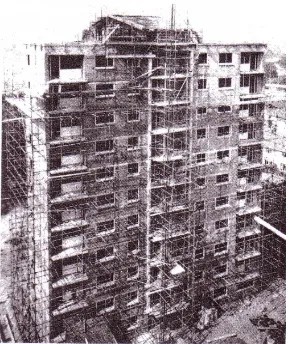
FIGURE 1.1 – THE PARTLY COMPLETED 19 STOREY HIGH-RISE BUILDING IN STUTTGART,
GERMANY (SOURCE: MALHOTRA 1976)...4
FIGURE 3.1 – CROSS SECTION OF A FLEXIBLE PAVEMENT... 27
FIGURE 3.2 – TYPICAL CROSS SECTION OF A RIGID PAVEMENT... 27
FIGURE 3.3 – A TYPICAL CROSS SECTION FOR A NO-FINES CONCRETE FOOTPATH OR BIKEWAY35 FIGURE 3.4 – TYPICAL CROSS SECTION OF A NO-FINES PAVEMENT FOR DRIVEWAYS AND PARKING LOTS... 36
FIGURE 3.5 – THE CROSS SECTION FOR A NO-FINES CONCRETE PAVEMENT WITH EXPANSIVE SOILS... 36
FIGURE 3.6 – A TYPICAL CROSS-SECTION FOR A PAVEMENT WITH AN IMPERVIOUS SUB-GRADE 37 FIGURE 3.7 – NO-FINES CONCRETE PAVEMENT CROSS-SECTION FOR HEAVILY TRAFFICKED AREAS... 38
FIGURE 4.1 – SHOWS THE COMPARISON BETWEEN THE DIFFERENT MIX PROPORTIONS AND BETWEEN 14 AND 28 DAY STRENGTH FOR THE NO-FINES CONCRETE CYLINDERS... 46
FIGURE 4.2 – THE FAILURE OF MIXES 1 AND 2... 47
FIGURE 4.3 – SHOWS THE FAILURE OF MIXES 3 AND 4... 48
FIGURE 4.4 – SHOWS THE FAILURE OF THE FOUR MIXES ON THE LARGE CYLINDERS... 49
FIGURE 5.1 – THE SHAKING DEVICE AND STACK OF SIEVES USED TO CONDUCT THE SIEVE ANALYSIS... 53
FIGURE 5.2 – SHOWS THE SLOTTED GAUGE USED TO DETERMINE THE FLAKINESS OF THE AGGREGATE PARTICLES... 57
FIGURE 6.1 – THE HALLWELD BENNETT PAN MIXER USED FOR THE NO-FINES CONCRETE MIXES ... 61
FIGURE 6.2 – THE EQUIPMENT REQUIRED TO CONDUCT A SLUMP TEST... 64
FIGURE 5.3 – SHOWS THE CONSISTOMETER AND OTHER MAJOR COMPONENTS USED IN THE VEBE TEST... 68
FIGURE 6.4 – THE APPARATUS USED TO CONDUCT THE COMPACTING FACTOR TEST... 72
FIGURE 7.1 – THE CAPPING MOULD USED FOR SULPHUR CAPPING... 79
FIGURE 7.2 – AVERY MACHINE USED TO CONDUCT THE CONCRETE TESTING... 81
FIGURE 7.3 – SHOWS THE SHEAR FAILURE MECHANISM OF THE NO-FINES CONCRETE (LEFT) AND CONVENTIONAL CONCRETE (RIGHT) AFTER COMPRESSIVE STRENGTH TESTING... 85
MADE FROM THE FIRST AGGREGATE... 87
FIGURE 7.6 – THE PLOT OF STRESS VERSUS COMPRESSION FOR A NO-FINES CONCRETE SAMPLE MADE FROM THE SECOND AGGREGATE SAMPLE... 88
FIGURE 7.7 – THE FAILURE OF THE NO-FINES CONCRETE SAMPLE ON COMPLETION OF THE
MODIFIED CUBE TEST... 92 FIGURE 7.8 – THE COMPRESSION MACHINE IS SET UP FOR AN INDIRECT TENSILE TEST... 93 FIGURE 7.9 – SHOWS THE ELONGATION OF THE CONCRETE SAMPLE UNDER A TENSILE STRESS96 FIGURE 7.10 –THE FAILURE OF THE NO-FINES CONCRETE AFTER AN INDIRECT TENSILE TEST.. 97
FIGURE 7.11 – SHOWS THE ELONGATION OF THE NO-FINES CONCRETE UNDER A TENSILE STRESS
... 97 FIGURE 7.12 – DIAGRAMMATIC VIEW OF A STANDARD FLEXURE TESTING APPARATUS (SOURCE:
AS 1012.11 – FIGURE 1)... 99
FIGURE 7.13 – THE PLOT OF STRESS VERSUS STRAIN FOR THE MODULUS OF RUPTURE TEST ON THE CONVENTIONAL CONCRETE SAMPLE... 101
FIGURE 7.14 – THE PLOT OF STRESS VERSUS STRAIN FOR THE MODULUS OF RUPTURE TEST ON THE NO-FINES CONCRETE SAMPLE... 102 FIGURE 7.15 – THE NO-FINES CONCRETE FLEXURAL TEST FAILURE ON COMPLETION OF THE
FOUR-POINT LOADING TEST... 103 FIGURE 7.16 – TYPICAL COMPRESSOMETER USED TO MEASURE THE LONGITUDINAL STRAIN... 105 FIGURE 7.17 – THE PLOT OF STRESS VERSUS STRAIN FOR A CONVENTIONAL CONCRETE SAMPLE
USED TO CONDUCT A MODULUS OF ELASTICITY TEST... 106
FIGURE 7.18 – THE PLOT OF STRESS VERSUS STRAIN FOR A CONVENTIONAL CONCRETE SAMPLE USED TO CONDUCT A MODULUS OF ELASTICITY TEST... 107
LIST OF TABLES
L
IST OF
T
ABLES
TABLE 4.1 – MIX PROPORTIONS USED FOR NO-FINES TRIAL MIXES... 43
TABLE 4.2 – THE DATA COLLECTED FROM THE TRIAL MIXES... 46
TABLE 5.1 – RESULTS OF THE SIEVE ANALYSIS... 54
TABLE 5.2 – DATA COLLECTED FROM THE FLAKINESS INDEX TEST... 58
TABLE 6.1 – THE SLUMP OF THE DIFFERENT CONCRETE SAMPLES... 65
TABLE 6.2 – THE TIME ELAPSED FOR THE COMPLETION OF THE VEBE TEST... 69
TABLE 6.3 – SHOWS THE COMPACTING FACTOR FOR ALL THE SAMPLES OF CONCRETE USED... 73
TABLE 7.1 – SHOWS THE FORCE DETERMINED FROM THE TESTING MACHINE AND THE CYLINDER COMPRESSIVE STRENGTH OF THE TEST SPECIMENS... 84
TABLE 7.2 – SHOWS THE FORCE DETERMINED FROM THE TESTING MACHINE AND THE COMPRESSIVE STRENGTH DETERMINED FROM THE MODIFIED CUBE TEST... 91
TABLE 7.3 – SHOWS THE RESULTS FROM THE INDIRECT TENSILE TEST... 95
TABLE 7.4 – SHOWS THE DATA COLLECTED AND THE CALCULATED MODULUS OF RUPTURE.... 100
TABLE 7.5 – SHOWS THE MODULUS OF ELASTICITY FOR THE FOUR PREVIOUS GRAPHS... 108
C
HAPTER
1
1. I
NTRODUCTION
1.1 INTRODUCTION TO NO-FINES CONCRETE
No-Fines concrete is a mixture of cement, water and a single sized coarse aggregate combined to produce a porous structural material. It has a high volume of voids, which is the factor responsible for the lower strength and its lightweight nature. No-fines concrete has many different names including zero-fines concrete, pervious concrete and porous concrete.
CHAPTER 1 INTRODUCTION
The force exerted on the foundations by no-fines concrete is approximately one third of that produced by the same structure constructed from conventional concrete. This difference may be of critical importance when considering structures on ground with a low bearing capacity (Fulton 1977).
No-fines concrete has been predominantly used in non-pavements applications, with only a limited use in pavements applications. The purpose of this project is to assess the suitability for no-fines concrete to be used for the construction of road pavements. This assessment will include investigating current literature on the topic and conducting some mix designs and standard concrete testing on conventional concrete and no-fines concrete to determine and compare their properties. From the tested data a conclusion as to the usefulness of no-fines concrete pavements will be drawn and it may be determined that further testing is required.
1.2 HISTORICAL BACKGROUND
however this expanded to five-storey buildings in the 1950’s and continues to expand. In recent years no-fines concrete has been used as a load bearing material in high rise buildings up to ten-storeys. The most remarkable use of this form of concrete was undertaken in Stuttgart, Germany where a high rise building was constructed using conventional concrete for the six bottom storeys and no-fines for the remaining thirteen upper storeys (Malhotra 1976).
CHAPTER 1 INTRODUCTION
The only reported use of no-fines concrete in Canada was the construction of a number of multistorey residential houses in the Toronto area around 1960.
No-fines concrete has been used in south-eastern America for the past 20 years in pavement applications. It was originally developed in Florida as a method of recharging the Everglade aquifers while controlling the water and reducing some of the detrimental effects caused by urban sprawl.
1.3 AIMS AND OBJECTIVES
No-fines concrete has been predominantly used in non-pavements applications with only a limited use in pavements applications. The purpose of this project is to assess the suitability of no-fines concrete to be used for the construction of road pavements. This assessment will include investigating current literature on the topic and also conducting some mix designs and standard concrete testing on conventional concrete and no-fines concrete to determine and compare their properties.
In order to achieve these aims, the following objectives had to be met:
1. Research background information relating to the use of no-fines concrete in pavement and non-pavement applications.
2. Conduct some initial mix design test to evaluate some possible alternatives. This will include using different water/aggregate/cement ratios.
3. Investigate some existing no-fines concrete pavement designs, construction specifications and maintenance procedures.
effectiveness of no-fines concrete as a road pavement.
1.4 CURRENT STATUS OF NO-FINES CONCRET
EAlthough there is very little documented use of no-fines concrete in Australia, it was first utilised as early as 1946. No-fines concrete was used in the construction of a residential house in Ryde, New South Wales. The Department of Works and Housing undertook this project as a method of investigating new cost effective construction materials (Ghafoori et al 1995).
Developers and government organisations have been using no-fines concrete more readily as a method of pollution control in America. Pervious surfaces are in greater demand as planners, public works officials and developers search for methods to adequately and efficiently manage storm water in an economical and environmentally friendly method (Frentress et al 2003). This form of concrete allows the water to penetrate the soil, reducing the runoff and stopping the movement of pollutants.
CHAPTER 1 INTRODUCTION
1.5 NON-PAVEMENT APPLICATIONS OF NO-FINES CONCRETE
No-fines concrete has had numerous useful non-pavement applications including buildings, tennis courts, drains and draintiles and floors in greenhouses.
No-fines concrete has been utilised by European countries in many different building situations. It has been used for cast-in-place load-bearing walls in houses, multi-storey and high-rise buildings, as prefabricated panels and steam-cured blocks.
A prominent use of no-fines concrete in Europe is in tennis court applications. The only variation from a normal mix is the slightly smaller aggregate used to provide a smoother playing surface. The permeability of the no-fines concrete reduces the time taken for water to drain and the surface to be playable (Ghafoori et al 1995).
Water and Power Resources Services in America successfully tested the use of drains and draintiles constructed from no-fines concrete beneath hydraulic structures. This application made it possible to reduce the uplift pressure on the structures and to drain ground water from beneath infrastructure like sewer pipes (Ghafoori et al 1995).
1.6 PAVEMENT APPLICATIONS OF NO-FINES CONCRETE
The majority of pavement applications for no-fines concrete are low volume road surfacing, parking lots and pavement edge drains.
No-fines concrete pavements were developed after some success with open graded asphalt and their applications in parking lots and service roads. Open graded asphalt is a mix of even graded aggregate, small amounts of fines and a bituminous material. This road surfacing has a relatively high void ratio, normally ranging between 18 and 25 percent (Ayers 2004).
Many road pavement trials were conducted throughout the world, initially with little or no success. One of these tests was conducted in England, where a group of engineers experimented with the monolithic casting of a no-fines wearing course over a conventional rigid pavement. This road was considered a failure after the ponding of water and the occurrence of ravelling 10 years after construction. Many factors had an influence on the results here, not least the clogging of the voids with dirt caused by the movement of farm machinery along the road (Ghafoori et al 1995).
CHAPTER 1 INTRODUCTION
The use of no-fines concrete as an edge drain or porous hard shoulders has been undertaken extensively in France. Excessive uplift pressures produced in concrete pavements lead to the development of methods to rapidly drain water from the pavement base (Ghafoori et al 1995).
1.7 MERITS AND DEMERITS OF USING NO-FINES CONCRETE
1.7.1 ECONOMICAL BENEFITS
The initial costs of no-fines concrete pavements are higher than those for conventional concrete pavements. This is due to two factors, the materials used are slightly more expensive and the increased thickness of the no-fines pavement compared to conventional pavements. However, in the long term, no-fines concrete pavements are more cost effective.
There are lower installation costs associated with the use of no-fines concrete because the need for underground piping and storm drains are eliminated. No major earthworks are required since the pavement does not need to slope to gutters and drains for adequate water control methods. The system does not require the upgrading of existing storm sewer systems, as there is little or no runoff.
required for the no-fines pavement. This is due to the light colour of the pavement, which reflects light, thereby reducing the installation and operating costs.
No-fines concrete is a sustainable material that has a life expectancy similar to that of conventional concrete. Correctly constructed no-fines pavements should have a life expectancy of 20 to 40 years and thus a lower life-cycle cost, according to the Southern California Mixed Concrete Association.
1.7.2 ENVIRONMENTAL BENEFITS
The benefits to the environment are many when using no-fines concrete. No-fines concrete pavements are light in colour, which helps to reduce the ground level ozone by lowering the temperatures in and around major cities. This is achievable due to the open cell structure of the concrete, which does not absorb and store heat and later radiate it back into the environment the way asphalt surfaces do. The open structure also draws on the cooler earth temperatures below the pavement to keep the pavement temperatures down.
CHAPTER 1 INTRODUCTION
1.7.3 WATER HAZARDS
Standing water is a common problem associated with concrete pavements. This is compounded by torrential rain, which makes the pavement surface slippery. Aquaplaning becomes a real danger for cars and can cause damage to the road users and public. No-fines concrete does not suffer from these inadequacies since a large volume of water will be stored instantly within the pavement (http://www.perviouspavement.com).
1.7.4 LIMITATIONS OF USE
Although no-fines concrete is a versatile material able to be used in many situations there are times when its use is not a viable choice. No-fines concrete pavements have a rough-textured, honeycomb like surface, which lacks the high bonding strength on the wearing course. Moderate amounts of ravelling are normal with little or no problems but this becomes a major issue on highly trafficked roadways. This problem is being investigated with the top 12 mm being ground away so the exposed aggregate have stronger bonds with the surrounding material.
1.7.5 CLOGGING OF PAVEMENT VOIDS
Clogging of the no-fines concrete pavement can occur in areas where water will run from grassed or dirt areas and below highly vegetated areas. Soil is capable of clogging the pores and reducing the effectiveness of the pavement. These problems can be reduced or eliminated by correct design and routine maintenance of the pavement. The maintenance includes regular sweeping or vacuuming and the addition of supplements to help break down organic materials. Pressure washing may be required if the dirt has been washed from the surface into the underlying material. This procedure has been shown to restore the concrete to near new condition (www.pervious.info).
1.8 GENERAL DIFFICULTY PERTAINING TO THE USE OF NO-FINES
CONCRETE
CHAPTER 1 INTRODUCTION
1.8.1 LACK OF EXPERIENCE
The lack of experience existing with the use of no-fines concrete pavement stems from it being a relatively new product. The difference between the properties of no-fines concrete and conventional concrete requires it to be placed and compacted in a different manner. The low workability and self-compacting nature of the no-fines concrete results in only a minimal amount of rodding and compaction and no vibrating.
The different placement and compaction methods required are not widely understood. When these important procedures are not correctly undertaken it can have a detrimental affect on the strength, appearance and effectiveness of the pavement. This can affect the water permeating capacity of the pavement, reducing the environmental benefits associated with its use.
1.8.2 LACK OF PUBLIC AWARENESS
applications in Australia. This is because it is a recently developed material that has not been widely used in Australia. Developers and homeowners would more readily use this product if its benefits were publicised. In a society with an emphasis on supporting the environment, greener products should be encouraged and possibly enforced by the government in an attempt to reduce the negative impacts associated with urban sprawl.
1.9 DISSERTATION OVERVIEW
The dissertation has the following structure:
Chapter 1 provides an introduction and background relating to no-fines concrete and the objectives that will be covered in the project.
Chapter 2 provides a review of the relevant literature and a discussion of the general engineering properties of no-fines concrete.
Chapter 3 covers existing no-fines concrete pavement designs, specifications and maintenance requirements.
Chapter 4 explains the tests and testing methodology to be used and the processes and results involved with the preliminary mix design.
CHAPTER 1 INTRODUCTION
Chapter 6 covers the workability tests conducted on the no-fines and conventional concrete samples before the test specimens were made.
Chapter 7 covers all the hardened concrete testing that occurred on the no-fines and conventional concrete specimens.
C
HAPTER
2
2. L
ITERATURE
R
EVIEW
2.1 INTRODUCTION
CHAPTER 2 LITERATURE REVIEW
2.2 LITERATURE REVIEW OF NO-FINES CONCRETE
The initial use of no-fines concrete was in the United Kingdom in 1852 with the construction of two residential houses and a sea groyne. It was a further 70 years before any further recorded use of no-fines concrete occurred when it was reintroduced into the United Kingdom in 1923 from Holland. The use of no-fines concrete became more important after the conclusion of World War II with the associated material shortages (Malhotra 1976).
Malhotra (1976) found that the density of no-fines concrete is generally about 70 percent of conventional concrete when made with similar constituents. The density of no-fines concrete using conventional aggregates varies from 1602 to 1922 kg/m3. A clinker aggregate was trialled and the no-fines concrete produced
a density of 961 kg/m3.
achieved during placement and curing, the formwork should not be removed after 24 hours as with conventional concrete. No-fines concrete has very low cohesiveness and formwork should remain until the cement paste has hardened sufficiently to hold the aggregate particles together. However, this is more of a consideration in low temperature conditions and when used in non-pavement applications where the concrete is not sufficiently supported by the ground or other means.
Ghafoori et al (1995) undertook a considerable amount of laboratory investigation to determine the effectiveness of no-fines concrete as a paving material. The curing types were investigated to determine if there was any difference between wet and sealed curing. There appeared to be only a negligible difference in strength between the different curing methods. It was clear from the test results that the strength development of no-fines concrete was not dependent upon the curing conditions.
CHAPTER 2 LITERATURE REVIEW
Abadjieva et al determined that the compressive strength of no-fines concrete increases with age at a similar rate to conventional concrete. The no-fines concrete specimens tested had aggregate-cement ratios varying from 6:1 to 10:1. The 28 day compressive strength obtained by these mixes ranged from 1.1 and 8.2 MPa, with the aggregate-cement ratio of 6:1 being the strongest. He concluded that the most plausible explanation for the reduced strength was caused by the increased porosity of the concrete samples. This strength is sufficient for structural load bearing walls and associated applications. Ghafoori et al (1995) produced no-fines concrete with a compressive strength in excess of 20 MPa when using an aggregate-cement ratio of 4:1.
Abadjieva et al investigated the influence of the aggregate-cement ratio on the tensile and flexural strength of no-fines concrete. This study only assessed aggregate-cement ratios ranging from 6:1 to 10:1. The highest strengths were obtained with an aggregate-cement ratio of 7:1 and the strength decreased with an increasing aggregate-cement ratio. He found that the tensile and flexural strengths of no-fines concrete were considerably lower than those obtained from conventional concrete, but he could not explain why the sample with the highest strength had a ratio of 7:1.
capillary action. Malhtora (1976) noted that the depth of penetration in no-fines concrete by this method under conditions of high humidity and no air movement is generally no greater than two or three times the largest aggregate diameter. The penetration of moisture was higher in no-fines concrete made from conventional aggregates than clinker aggregate.
Meininger (1988) investigated the effect on the properties of no-fines concrete with the addition of sand. He found that when a small amount of sand was added to the mixture, the compressive strength of the concrete increased from 10.3 MPa to 17.2 MPa. The sand added was between 10 and 20 percent of the aggregate by weight. The increased fines filled some of the voids, reducing the air content from 26 to 17 percent. A decrease in the voids causes the concrete to bond more effectively, thus increasing the compressive strength. With more than 30 percent sand the concrete started to display the properties of conventional concrete and did not have sufficient voids necessary for water flow.
No-fines concrete possessed good engineering properties for non-pavement applications such as buildings. Development of this material in pavement applications did not take off until the late 1970’s, where it was first used as a wearing course for a parking lot. The first no-fines concrete pavement design was patented as a ‘porous pavement’ and a following no-fines pavement design was called a ‘pervious pavement.’ Ghafoori et al (1995) found 53 no-fines concrete parking lots within the east and western coastlines of Florida, USA.
CHAPTER 2 LITERATURE REVIEW
Ravelling can occur in no-fines concrete pavements when there is a deficiency in the curing process or improper compaction and seating of the top aggregate particles. Meininger (1988) found that poor curing techniques allowed the cement paste to dry too rapidly and did not allow the hydration process to finish. It could be seen by the roughness of the pavement surface that no compaction was undertaken. All these factors affected one particular parking lot studied and started ravelling one year after construction. Another pavement was constructed and it was made sure that sufficient compaction was provided to ensure the top aggregate was correctly seated and covered with plastic to establish proper curing conditions.
2.3 GENERAL ENGINEERING PROPERTIES OF NO-FINES CONCRETE
The physical properties of the individual components and the no-fines concrete as a whole are extremely important and should be explored further. The rheology of the concrete and the individual materials determine properties like the strength, void ratio, durability and the chemical properties. All these properties need to be known and assessed to make the most appropriate choice for a particular application.
2.3.1 STRUCTURE
The structure of no-fines concrete varies significantly from conventional concrete in the sense that a small fillet of cement paste holds the materials together. The aggregate is covered with a thin layer of cement paste. When the compaction is undertaken it forces the aggregate particles together until they are in contact with each other. This squashes the cement paste out from the point of contact causing a fillet of cement paste to appear and bond the particles.
The no-fines concrete has an open structure with a high void ratio that relies on the bonding of the aggregate for strength. The structure is most easily explained as rice bubbles bonded together to produce a porous material.
2.3.2 SHAPE
CHAPTER 2 LITERATURE REVIEW
2.3.3 MIX PROPORTIONS
The mix proportions for no-fines concrete depends predominantly on the final application. In building applications, the aggregate-cement ratio used is leaner, usually ranging from 6:1 to 10:1. This leaner mix ensures that the void ratio is high and prevents capillary transport of water. However, in pavement applications the concrete strength is more critical and aggregate-cement mixes as low as 4:1 is used. This lower ratio ensures an adequate amount of bonding between the aggregate and cement to withstand the higher loads.
2.3.4 WATER CONTENT
2.3.5 AGGREGATE GRADING
The aggregate generally used in no-fines concrete applications usually ranges from 10 mm to 20 mm. Five percent oversized and ten percent undersized materials are acceptable for use but there should be no particles smaller than 5 mm (Neville 1997). If there are too many small particles it will tend to fill the voids, affecting the porosity of the concrete and the associated properties.
2.3.6 DENSITY
The density of no-fines concrete is dependent upon the void content in the concrete. Due to the high air content it is a lightweight concrete with a density of about two thirds of conventional concrete. The density of no-fines concrete normally ranges between 1600 and 1900 kg/m3. This is dependent upon the shape, size and density of the aggregate, the aggregate-cement-water ratio and the compaction exerted on the concrete.
2.3.7 AIR-VOID CONTENT
CHAPTER 2 LITERATURE REVIEW
2.3.8 SHRINKAGE
Drying shrinkage in no-fines concrete is relatively small but does vary depending on the aggregate-cement ratio. The difference in the amount of shrinkage can be attributed to the following factors. A reduction in the aggregate-cement ratio means there is more cement paste available to undergo volumetric contraction and shrinkage. At the same time, the decrease in aggregate-cement ratio causes the aggregate particles to induce a restraint on the drying shrinkage since they are in contact (Fulton 1977).
2.4 SUMMARY
No-fines concrete has properties capable of being used in road pavement applications. It suffers from a number of problems like lower compressive strength and ravelling but still has favourable properties that can be utilised in road pavement applications. The mix proportions and water content are critical when obtaining a sufficient bond between the aggregate particles.
C
HAPTER
3
3. N
O
-F
INES
C
ONCRETE
P
AVEMENT
D
ESIGN
&
M
AINTENANCE
3.1 INTRODUCTION
This chapter includes a brief explanation of the difference between flexible and rigid pavements. This is followed by the existing no-fines concrete pavement construction specifications and maintenance procedures used by Stoney Creek Materials, L.L.C.
3.2 ROAD PAVEMENTS
CHAPTER 3 NO-FINES CONCRETE PAVEMENT DESIGN & MAINTENANCE
Figure 3.1 – Cross Section of a Flexible Pavement
Traditional rigid pavements consist of a concrete slab on top of an unbound granular sub-base and a sub-grade consisting of insitu materials. A typical cross-section of a rigid pavement is shown below in Figure 3.2.
Figure 3.2 – Typical Cross Section of a Rigid Pavement Bituminous Surfacing
Unbound Granular Base Course
Unbound Granular Sub-base
Sub-grade (insitu material)
Pa
ve
m
en
t S
tr
uc
tu
re
Concrete Slab
Unbound Granular Sub-base
Sub-grade (insitu material)
Pa
ve
m
en
t S
tr
uc
tu
3.3 NO-FINES CONCRETE PAVEMENTS
No-fines concrete pavements are a form of rigid pavement but differ substantially due to the materials used during construction. The no-fines pavements consist of a concrete slab over a clean aggregate sub-base, a filter fabric and a permeable sub-grade. This insitu material is important, as it is required to be permeable to allow the water in the sub-base to penetrate the soil. The following sections will set out some guidelines relating to the construction and maintenance required for no-fines concrete pavements.
Stoney Creek Materials, L.L.C. have set out the following guidelines in relation to their Pervious Pavement System (www.stoneycreekmaterials.com). They are one of many companies with their own set of guidelines and were chosen as they provided the most useful and detailed information.
3.3.1 SUB-GRADE AND SUB-BASE REQUIREMENTS
CHAPTER 3 NO-FINES CONCRETE PAVEMENT DESIGN & MAINTENANCE
3.3.1.1 SUB-GRADE PERMEABILITY
The permeability of the sub-grade is important as it dictates the effectiveness of the no-fines pavement. Prior to the placement of the no-fines pavement the sub-grade has to be tested for the rate of permeability with a suitable sub-sub-grade permeability test. The minimum sub-grade percolation rate acceptable for no-fines concrete pavements is 2.5 mm per hour, providing local water quality regulations relating to sedimentation, filtration and detention are met.
3.3.1.2 SUB-GRADE TREATMENT
The organic material in the sub-grade is required to be scarified to a minimum depth of 75 mm. This material requires a proof roll to identify any weak or wet areas that may cause premature pavement failures. Fill material may be incorporated if it is clean and free from deleterious materials as specified by a geotechnical study.
The sub-grade is required to be in a moist condition before the construction of the pavement sub-base. The moisture content should be within 3 percent of the optimum moisture content as determined by a compaction test.
3.3.1.3 FILTER FABRIC
3.3.1.4 SUB-BASE MATERIAL
The sub-base is made up of a clean aggregate that is retained on a 37 mm sieve and passes through a 50 mm sieve. It must not contain any fines, as this will affect the performance of the pavement. A washed riverbed rock or crushed stone would be the most appropriate material for this situation.
Compaction on the sub-base will occur in a single pass with the use of a plate or roller compactor to provide a smooth uniform working surface. Any irregularities in the sub-grade will be smoothed during this phase of construction. This aggregate is required to be saturated before the concrete is poured to minimise the loss of moisture from the concrete.
The thickness of this sub-base layer is dependent upon the underlying sub-grade and the intended use for the pavement. This layer ranges in thickness from 100 mm for footpaths to 250 mm for heavily trafficked areas.
3.3.2 MIXING, PLACING AND FINISHING REQUIREMENTS
CHAPTER 3 NO-FINES CONCRETE PAVEMENT DESIGN & MAINTENANCE
3.3.2.1 MIX TIME
The time for mixing no-fines concrete is the longer of either 75 revolutions or 10 minutes. When using a high mix speed the addition of admixture to increase the flow ability of the aggregate/cement mix is required to ensure adequate strength. Most standard cement mixers do not require the addition of admixtures when mixing no-fines concrete.
3.3.2.2 CONCRETE DISCHARGE METHOD
The concrete discharging mechanism should be continuous for conformity of the pavement. The concrete must be discharged as close as possible to the final placement. This placement must overlap the previously discharged concrete and the concrete should not be pulled or shovelled to the final resting place as this will disturb the underlying material and affect the pavement strength.
3.3.2.3 JOINTING REQUIREMENTS
3.3.2.4 PLACING AND FINISHING EQUIPMENT
The placing and finishing equipment required for the placement of the no-fines concrete is a mechanical machine similar to a paving machine used in asphalt applications which is capable of providing 69 kPa (10 psi) of vertical force. The only vibration applied to the pavement will be from the screed that is providing the compaction. The vibration must be stopped whenever the machine or screed is not moving. Vibration should be limited, as excessive vibration negatively impacts on the strength of the concrete.
3.3.2.5 CURING REQUIREMENTS
The curing process begins within 20 minutes of placement and it is at this time that a curing agent must be applied to all surfaces. A second application may be appropriate and can be applied when the first has dried. In extreme weather conditions it is recommended that the surfaces be covered with a polyethylene sheet. This can be done as soon as the curing agent has become tacky and should remain on the surface for a minimum of 72 hours (http://www.stoneycreekmaterials.com).
3.3.3 NO-FINES CONCRETE PAVEMENT MAINTENANCE
CHAPTER 3 NO-FINES CONCRETE PAVEMENT DESIGN & MAINTENANCE
The vacuuming removes any surface silt or debris that is capable of clogging the pavement. The frequency of vacuuming should be increased in situations where there is overhanging vegetation, excessive surrounding dirt areas and other pollutants that reduce the voids of the pavement.
The high-pressure washing is required to flush contaminants from the no-fines concrete into the underlying sub-base. The excess material in the sub-base has not been shown to reduce the effectiveness of the no-fines pavement.
3.3.3.1 HYDROCARBON CLEAN-UP
Hydrocarbons are broken down by naturally occurring micro-organisms present in most soils. The micro-organisms will aerobically break down the hydrocarbons provided there is a sufficient amount of oxygen and nutrients. Supplements can be provided to ensure sufficient nutrients and the proper functioning of these organisms.
3.3.3.2 ORGANIC BUILD-UP
3.3.3.3 SIGNAGE
In cases where the pavement is used by a large number of people it is important to provide signage informing everyone of the ecological sensitivity of the pavement. It should set out some guidelines that need to be adhered to. This includes no piling of any material without covering the surface and contacting the owner to treat any spills example to prevent pavement contamination.
3.4 PAVEMENT SPECIFICATIONS
The previous sections set out the requirements for the sub-grade, sub-base and no-fines wearing course. The following section assesses some of the designs that have been used in different situations.
3.4.1 FOOTPATHS AND BIKEWAYS
CHAPTER 3 NO-FINES CONCRETE PAVEMENT DESIGN & MAINTENANCE
Figure 3.3 – A typical cross section for a no-fines concrete footpath or bikeway
3.4.2 STANDARD PAVEMENTS
There are a number of pavements that have been classified as standard pavements that can be used in situations such as residential driveways and footpaths. These differences are predominantly concerned with the sub-grade type.
This pavement consists of a non-woven geotextile fabric over the sub-grade and a 200 mm thick clean aggregate for the sub-base. This is covered by 100 mm of no-fines concrete and is shown in figure 3.4 (www.stoneycreekmaterials.com).
No-Fines Concrete
37 – 60 mm Clean Aggregate
Sub-Grade
60
m
m
10
0
m
m
Figure 3.4 – Typical cross section of a no-fines pavement for driveways and parking lots
The following figure shows the pavement cross-section with a sub-grade made from an expansive soil. This consists of an impervious layer of polyethylene between the sub-grade and sub-base. The 200 mm sub-base and 100 mm no-fines concrete are the same as the previous standard pavement. It requires a number of 300 to 500 mm cased borings that continue through the expansive soil filled with riprap. The spacings required for these borings will be specified in the geotechnical study to assess the permeability (www.stoneycreekmaterials.com).
No-Fines Concrete
37 – 60 mm Clean Aggregate
Sub-Grade
10
0
20
0
m
m
Non-Woven Geotextile Filter Fabric
10
0
m
m
20
0
m
m
No-Fines Concrete
37 – 60 mm Clean Aggregate
Expansive Sub-grade
100 – 150 mm Riprap
300 – 500 mm Impervious
CHAPTER 3 NO-FINES CONCRETE PAVEMENT DESIGN & MAINTENANCE
[image:50.595.139.501.292.500.2]The final standard pavement consists of an impervious sub-grade. This requires boring holes through the impervious layer into a permeable layer that allows the water to dissipate. The size of the borings will range between 300 and 500 mm in diameter and spacings will be determined from a geotechnical study. The sub-base required is 200 mm and the no-fines concrete is 100 mm thick. Figure 3.6 shows the cross section of the standard pavement with an impervious sub-grade (www.stoneycreekmaterials.com).
Figure 3.6 – A typical cross-section for a pavement with an impervious sub-grade
3.4.3 HEAVY TRAFFIC PAVEMENT
The pavement for heavy and large traffic volumes consists of a 150 mm layer of no-fines concrete and a 250 mm thick layer of 37 to 50 mm clean aggregate. A non-woven geotextile fabric is placed between the clean aggregate and the sub-grade. This arrangement is shown diagrammatically in the figure below.
10
0
m
m
20
0
m
m
No-Fines Concrete
37 – 60 mm Clean Aggregate
Impervious 100 – 150 mm Riprap
Figure 3.7 – No-fines concrete pavement cross-section for heavily trafficked areas
The no-fines concrete pavements shown in the previous sections have been designed on the performance of previously constructed roads. It has been based on empirical evidence collected from the pavements that have failed and those that have been successful. Currently there is no theoretically based pavement design method for no-fines concrete pavements. This means that the pavements currently in use may be over designed and the pavement cost could be reduced if there was a better understanding of how the various components interact. With a greater understanding of the critical characteristics of all the components, new or improved materials may be found to increase the performance of the pavement.
No-Fines Concrete
37 – 60 mm Clean Aggregate
Sub-Grade
15
0
m
m
25
0
m
m
CHAPTER 3 NO-FINES CONCRETE PAVEMENT DESIGN & MAINTENANCE
3.5 SUMMARY
This chapter covered the construction and maintenance procedures that Stoney Creek Materials recommend to be used in conjunction with their no-fines concrete pavements. A number of different pavements were discussed, ranging from pedestrian footpaths to highly trafficked roadways. The different treatments available to be used in unfavourable soil conditions were also discussed.
C
HAPTER
4
4. M
ETHODOLOGY
& P
RELIMINARY
M
IX
D
ESIGN
4.1 INTRODUCTION
The following sections of this chapter describe in detail the testing that follows and the methodology used to produce the results to be analysed. A discussion of the preliminary mix design that was conducted during the early stages of this project follows.
CHAPTER 4 METHODOLOGY & PRELIMINARY MIX DESIGN
4.2 TEST METHODOLOGY
This project is focused predominantly on the use of no-fines concrete as a road pavement material. As this is a comparison between no-fines concrete pavements and conventional concrete pavements, there is a requirement that the tests being conducted can occur on both samples.
The test procedure included the initial steps of deciding on the tests to be conducted and choosing a number of aggregate-cement ratios for the no-fines concrete. This was followed by conducting the preliminary mix design and compressive strength tests on these samples to determine the mix that performed most successfully.
With the mix ratio known, the remaining testing began. This included determining the properties of the aggregate being used with a sieve analysis and a flakiness index test. After mixing, the workability testing was conducted on the wet concrete before the test specimens were constructed.
4.3 CONCRETE TESTS
The tests that were conducted had to provide a complete picture of all the characteristics of the concrete in both the wet and hardened state.
For this reason, it was proposed that the testing incorporate aggregate testing to determine the potential effect of the aggregate shape on the performance of the no-fines concrete. This was followed by conducting workability tests like the slump, VEBE and compacting factor tests on the wet concrete sample.
The hardened concrete tests proposed for the project were compressive strength and indirect tensile tests, modulus of rupture and elasticity and the skid resistance test. This testing includes determining the void ratio and assessing the permeability of the no-fines concrete.
4.4 MIX DESIGN
CHAPTER 4 METHODOLOGY & PRELIMINARY MIX DESIGN
4.4.1 CONVENTIONAL CONCRETE
There was no mix design undertaken for conventional concrete, since the strength of certain mixes is readily known. This meant that no trials were required to be carried out. When conducting the tests to determine the properties of a conventional concrete, a 32 MPa ready-mixed concrete was used in conjunction with another concrete project.
4.4.2 NO-FINES CONCRETE
The mix designs for no-fines concrete were obtained from printed articles. There were a large number of different mixes that are currently being used for a whole range of applications. For this reason four different mixes were trialled. The aggregate-cement-water ratio mixes were:
Aggregate Cement Water
8 1 0.4
6 1 0.4
4.5 1 0.4
4.8 1 0.36
Table 4.1 – Mix Proportions used for No-fines Trial Mixes
[image:56.595.234.391.487.582.2]4.4.3 TRIAL MIX
The trial mixes were used to determine the most suitable mixture for the analysis. The four different samples were mixed and tested for compressive strength and indirect tensile strength at 14 days. From these results, the most appropriate mix was determined and used for the remainder of the analysis. The 28 day strength was tested later to ensure that the chosen concrete mix possessed the highest ultimate compressive strength of the concrete mixes.
4.4.3.1 APPARATUS
Wheelbarrow – capable of resisting chemical attack from the cement and of sufficient size to allow hand mixing.
Shovel – capable of resisting chemical attack and abrasion during the mixing process.
Balance – capable of weighing the required mass with an accuracy of 0.1 g and complying with AS 1141.2.
4.4.3.2 MIXING PROCESS
1. Weigh aggregate, cement and water for the mix.
2. Moisten the working surface of the wheelbarrow to prevent the materials from sticking to the sides.
CHAPTER 4 METHODOLOGY & PRELIMINARY MIX DESIGN
4. Spread the cement and water uniformly over the surface of the aggregate. 5. Mix the concrete until the aggregate is evenly covered with cement paste.
4.4.3.3 COMPACTING AND CURING
Rodding was adopted for the compaction of no-fines concrete. The concrete samples were tamped 25 times and split into three layers. This procedure ensures sufficient compaction has been produced.
The curing process starts with the moulds being left in place for 2 or 3 days, to allow sufficient bonding between the aggregate particles. After the specimens were removed from the mould they were placed in the fog room until the time of testing. This process was used to ensure that optimum curing was achieved.
4.4.3.4 RESULTS AND ANALYSIS
Aggregate- Cement-Water Ratio Compressive Strength (MPa) Indirect Tensile Strength (MPa) Compressive Strength (MPa) Compressive Strength of Large Cylinders
(MPa)
4.33 3.06
8:1:0.4
4.33 1.19 3.82 6.00
5.60 7.51
6:1:0.4
8.02 1.58 7.64 5.49
7.77 11.20
4.5:1:0.4
7.89 2.32 12.99 7.70
7.89 6.37
4.8:1:0.36
7.26 1.08 6.24 5.32
Table 4.2 – The data collected from the trial mixes
0.00 2.00 4.00 6.00 8.00 10.00 12.00 14.00 C om pr es si ve S tr en gt h (M P a)
8 : 1 : 0.4 8 : 1 : 0.4 6 : 1 : 0.4 6 : 1 : 0.4 4.5 : 1 : 0.4 4.5 : 1 : 0.4 4.8 : 1 : 0.36 4.8 : 1 : 0.36 Mix Proportions (Aggregate:Cement:Water)
Trial Mix Compressive Strength
14 Day Strength 28 Day Strength
[image:59.595.134.499.444.661.2]CHAPTER 4 METHODOLOGY & PRELIMINARY MIX DESIGN
From the 14 day testing, the aggregate-cement-water ratio of 4.5:1:0.4 was chosen as the most suitable mix since it produced the highest average compressive strength and possessed the greatest indirect tensile strength. The rest of the analysis will be completed using this mix design.
The large variation in the values obtained was caused predominantly by the inability to adequately seat the specimens. Rubber capping was used to try and overcome this problem but the aggregate size made providing a smooth surface hard to achieve. It was determined that the use of sulphur capping or similar methods would be more suitable to eliminate the problem of tilting and failing due to the dislodging of the edge aggregate.
The specimens tended to fail slightly and then regain strength before failing again. This process continued until the ultimate failure occurred. At times this failure was catastrophic and can be seen in the figure below, which shows the failure of the specimens on completion of 28 day compression testing. This anomaly can be explained by the poor bonding of the top aggregate particles and should be eliminated by sulphur capping, as it will strengthen the bond of these particles.
Figure 4.3 – Shows the failure of Mixes 3 and 4
The failure shown in the previous two figures vary from slight shear failure with only small amounts of the concrete missing from the edges, to nearly complete disintegration with only small fragments still visible.
CHAPTER 4 METHODOLOGY & PRELIMINARY MIX DESIGN
Figure 4.4 – Shows the failure of the four mixes on the large cylinders
4.5 SUMMARY
The no-fines concrete mix design found that an aggregate-cement-water mix of 4.5:1:0.4 produced the highest compressive strength out of the different mix proportions trialled. Since the highest compressive strength was found in the 4.5:1:0.4 mix, it was used for the remainder of the testing in this project.
CHAPTER 5 PROPERTIES AND TESTING OF AGGREGATE
C
HAPTER
5
5. P
ROPERTIES AND
T
ESTING OF
A
GGREGATE
5.1 INTRODUCTION
This chapter investigates the properties of the aggregate used to make the no-fines concrete test samples. A sieve analysis and flakiness index of the aggregate sample was determined, so the characteristics of the aggregate could be assessed.
5.2 SIEVE ANALYSIS
Sieve analysis is a method of determining the grading of a particular aggregate or a mixture of aggregates. The sieve analysis is carried out in a mechanical sieving machine to provide a more consistent result and achieve much greater accuracy. The sieves used vary in size but consecutive sieves used are smaller in aperture as you move down the stack. There are three different methods for undertaking a sieve analysis. Two wet analysis methods can be used, one with alcohol and the other with water. The third method is dry analysis, which can only be used for granular particles larger than 125 m.
The aggregate was dry sieved due to the large particle size. Before sieving began the aggregate particles were air dried to ensure that no lumps or small particles contaminated the larger sieves and to prevent the smaller sieves from becoming clogged. The test sample was reduced from a large quantity by the method of ‘sample reduction’. The aggregate was riffled and collected in boxes at the bottom of the chutes. Half was discharged and the other half was riffled again. This process was continued until the specifications for sampling were met and an adequate quantity of material collected for the sieve analysis.
5.2.1 APPARATUS
The following apparatus complying with the appropriate Australian Standards were used in all cases.
CHAPTER 5 PROPERTIES AND TESTING OF AGGREGATE
Balance – capable of weighing the required mass with an accuracy of 0.1 g and complies with AS 1141.2.
Sample Divider – capable of handling the size aggregate to be passed, usually the slot width is 10% wider then the aggregate and complies with AS 1141.2.
Test Sieves – a certified set of sieves with a lid and collection pan to comply with AS 1152.
Brush – capable of removing all aggregate from the sieves, without damaging the sieves.
Shaking Device – a machine capable of providing lateral and vertical movement that ensures the continuous movement of the aggregate over the sieves.
5.2.2 PROCEDURE
A brief outline of the procedure, which complies with AS 1774.19 – 2003, follows:
1. The mass of the dry sample obtained from the riffler was measured with an accuracy of 0.1 g.
2. Dry, clean sieves were stacked in order with the largest sieve on the top and collection pan on the bottom.
3. The sample was placed on the top sieve, the lid replaced and the nest of sieves positioned on the shaking device which was operated for 10 minutes.
4. The contents of each sieve were removed separately and the mass of aggregate retained by each sieve weighed.
5.2.3 RESULT OF SIEVE ANALYSIS
The results of the sieve analysis conducted on the 20 mm aggregate used to prepare the test samples are shown below in Table 5.1.
Sieve Size
(mm) Mass Retained (g) Retained (g) Sum Mass Retained (%) Percentage Passing (%) Percentage
19 160.2 160.2 3.56 96.44
16 855 1015.2 22.59 77.41
9.5 3235.4 4250.6 94.56 5.44
6.7 153.1 4403.7 97.97 2.03
4.75 38.2 4441.9 98.82 1.18
< 4.75 53.1 4495 100.00 0.00
TOTAL 4495
CHAPTER 5 PROPERTIES AND TESTING OF AGGREGATE
The results of the sieve analysis show that this 20 mm aggregate sample is not completely single sized but reasonably close. Almost 95 percent of the aggregate was retained on or above the 9.5 mm sieve. There were small amounts of fines and small aggregate, which should not affect the strength of the no-fines concrete but could affect the void ratio.
A sieve analysis was also undertaken on the second sample of 20 mm aggregate obtained to make the no-fines concrete samples. This second sieve analysis was conducted as there was a large variation in the strength of the two concrete samples. The details of this test can be found in Appendix C along with a grading curve for both aggregate samples. Both aggregate samples appeared to be a single-sized aggregate.
5.3 FLAKINESS INDEX
The purpose of determining the Flakiness Index is to find the quantity of flaky or thin aggregate particles. The flakiness of the aggregate particles is of critical importance to the strength of no-fines concrete. The flaky particles can crush under load causing premature failure of the concrete. The flaky particles will tend to lie flat on each other reducing the void content and the permeability of the concrete. If the voids are not large enough it will suffer from internal stress caused by the capillary action of the water.
5.3.1 APPARATUS
The following apparatus used in testing complies with the appropriate Australian Standards.
Drying Oven – capable of maintaining a temperature of 110 ± 5ºC and complies with AS 1141.2.
Balance – capable of weighing the required mass with an accuracy of 0.1 g and complies with AS 1141.2.
Sample Divider – capable of handling the size aggregate to be passed, usually the slot width is 10% wider then the aggregate and complies with AS 1141.2.
CHAPTER 5 PROPERTIES AND TESTING OF AGGREGATE
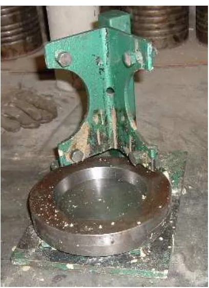
Figure 5.2 – Shows the slotted gauge used to determine the Flakiness of the aggregate particles
5.3.2 PROCEDURE
1. The mass of the sample retained on each sieve was weighed separately and the test fraction recorded to the nearest gram (m1).
100
1 2×
Σ Σ =
m m FI
where
m2 = sum of the masses of selected entire size fractions passing
the slotted gauge, in grams
m1 = sum of the masses of selected entire size fractions, in
grams.
4. Report the flakiness index obtained from the previous calculation to the nearest whole number.
5.3.3 RESULT OF FLAKINESS INDEX
The Flakiness Index obtained from testing the aggregate sample is shown in Table 5.2.
Aggregate Size (mm)
M1
(g)
M2
(g)
Flakiness Index
19 160 22 13.75
16 855 115 13.45
9.5 616 70 11.36
6.7 153 33 21.57
4.75 59 13 22.03
1843 253 13.73
CHAPTER 5 PROPERTIES AND TESTING OF AGGREGATE
The aggregate sample has a Flakiness Index of 13.73 percent by weight. This means that the amount of flaky particles in the sample is 13.73 percent. Flaky particles are not wanted when making no-fines concrete as it initiates aggregate crushing and promotes poor contact between particles.
This amount of flaky particles will slightly reduce the ultimate strength of the no-fines concrete. A spherical aggregate shape is most desirable for no-no-fines concrete applications. The flaky particles are probably causing a small loss of strength but this quantity should not affect the outcome dramatically.
The flakiness index from the second aggregate sample is 10.97, which is different to the previous sample. It can be deduced from this that the flakiness of the aggregate particles affects the compressive strength of no-fines concrete, as the concrete made from this sample was considerably stronger.
5.4 SUMMARY
It was found that there was a discrepancy in the flakiness of the two aggregate samples used. The lower amount of flaky particles meant that a higher compressive strength could be obtained. This upholds what is stated in the literature.
C
HAPTER
6
6. W
ORKABILITY
T
EST OF
C
ONCRETE
S
AMPLES
6.1 INTRODUCTION
This chapter includes the no-fines concrete mix preparation procedure and the workability tests. The workability tests include the slump, VEBE and compacting factor tests. These tests were chosen as they will provide a clear indication of the workability and fresh concrete characteristics.