University of Southern Queensland
Faculty of Engineering and Surveying
Bioretention Basin
Best Practice Design Guidelines
A dissertation submitted by
Selina Boskovic
In fulfilment of the requirements of
Courses ENG4111 and 4112 Research Project
Towards the degree of
Bachelor of Engineering (Civil Major)
Abstract
A ‘best practice’ design guideline for a bioretention basin is concluded by comparing and critically evaluating existing design guidelines, along with studies on their performance. Further, an appropriate naming convention for a bioretention basin is sought and concluded.
Bioretention basins (which are an aspect of Water Sensitive Urban Design) seek to maintain near-to natural flow levels at storm water receiving waters (by retention of storm runoff) and treat storm runoff to remove pollutants at-source in urbanised areas. This minimises the consequences on receiving waterways caused by urbanisation. The increase in impervious area in an urbanised area causes disruption to the natural hydrologic cycle and an increase in stormwater pollutant load.
Many different guidelines exist for bioretention basin design due to simultaneous evolution of the technology in various locations around the world. A consensus on ‘best practice’ design principles is needed.
The design guidelines of bioretention basins are easily divided into separate design elements. This enables comparison and critical evaluation to be undertaken in terms of each design element to conclude an overall ‘best practice’ design guideline for the system. Recommendations for further research into some of these design elements are presented due to conflicting information in the publications reviewed or a lack of information. Twelve design guidelines and twelve studies from the USA and Australia are used as a source of information.
The naming convention is also compared in the various publications reviewed and other literature. The most appropriate term for a bioretention basin is ‘bioretention’ followed by either ‘basin’, ‘system’, ‘cell’, ‘area’ or ‘facility’.
Certification
I certify that the ideas, designs and experimental work, results, analyses and conclusions set out in this dissertation are entirely my own effort, except where otherwise indicated and acknowledged.
I further certify that the work is original and has not been previously submitted for assessment in any other course or institution, except where specifically stated.
Selina Boskovic
Student Number: 0050035553
_______________________________ Signature
_______________________________
Acknowledgements
Table of contents
Abstract ...i
Certification ...iii
Acknowledgements ...iv
Table of contents ... v
List of figures ...viii
List of tables...ix
List of appendices ...xi
Nomenclature ...xii
Chapter 1 Introduction and overview... 1
1.1. Introduction ... 1
1.2. Background ... 1
1.2.1 Urbanisation impacts... 1
1.2.2 Water sensitive urban design (WSUD) ... 3
1.2.3 Bioretention basins... 5
1.2.4 Bioretention swales ... 7
1.2.5 Sand filters ... 8
1.3. Project aims... 9
1.4. Specific objectives ... 13
1.5. Methodology ... 14
Chapter 2 Bioretention basin publications reviewed ... 17
2.1. Name of publication... 17
2.2. Basis of publication... 20
Chapter 3 Identification of a bioretention basin... 22
Chapter 4 Bioretention basin naming convention... 31
Chapter 5 Bioretention basin design elements ...34
5.1. Catchment area requirements... 35
5.2. Design flows establishment procedure... 35
5.3. Detention volume establishment procedure ...37
5.4. Depth of ponding requirements... 40
5.5. Sizing of basin surface area... 42
5.6. Pretreatment measures ...45
5.7. Vegetation specification... 48
5.8. Mulch layer design procedure... 51
5.9. Planting layer design procedure ... 52
5.10. Filter media design procedure... 53
5.10.1 Hydraulic conductivity... 53
5.10.2 Organic content ... 58
5.10.3 Depth requirements ... 60
5.10.4 Planting/mulch layer inclusion... 62
5.10.5 pH... 63
5.10.6 Salt content...64
5.10.7 Type of soil ...64
5.10.8 Phosphorus content ... 67
5.10.9 Other requirements...69
5.11. Transition layer design procedure...71
5.13. Nitrogen removal zone design procedure ... 76
5.14. Infiltration rate of system design procedure... 79
5.15. Perforated underdrains design requirements... 80
5.16. Inspection requirements ... 83
5.17. Impervious liner requirements ... 84
5.18. Groundwater considerations ... 88
5.19. Bypass system requirements and design procedure ... 89
5.20. Inlet design procedure ... 93
5.21. Traffic lane flow widths checking procedure... 93
5.22. Inlet scour requirements... 95
5.23. Scour across vegetation layer checking procedure ... 97
Chapter 6 Best practice design guidelines ... 99
6.1. Catchment area requirements... 100
6.2. Design flows establishment procedure... 100
6.3. Detention volume establishment procedure ...100
6.4. Depth of ponding requirements... 100
6.5. Sizing of basin surface area... 101
6.6. Pretreatment measures ...102
6.7. Vegetation specification... 104
6.8. Mulch layer design procedure... 106
6.9. Planting layer design procedure ... 106
6.10. Filter media design procedure... 106
6.10.1 Hydraulic conductivity... 106
6.10.2 Organic content ... 108
6.10.3 Depth requirements ... 109
6.10.4 Planting/mulch layer inclusion... 109
6.10.5 pH... 109
6.10.6 Salt content... 109
6.10.7 Type of soil ... 110
6.10.8 Phosphorus content ... 110
6.10.9 Other requirements... 111
6.11. Transition layer design procedure... 112
6.12. Drainage layer design procedure... 112
6.13. Nitrogen removal zone design procedure ... 114
6.14. Infiltration rate of system design procedure... 114
6.15. Perforated underdrains design requirements... 114
6.16. Inspection requirements ... 115
6.17. Impervious liner requirements ... 116
6.18. Groundwater considerations ... 116
6.19. Bypass system requirements and design procedure ... 116
6.20. Inlet design procedure ... 117
6.21. Traffic lane flow widths checking procedure... 118
6.22. Inlet scour requirements... 118
6.23. Scour across vegetation layer checking procedure ... 119
Chapter 7 Limitations, recommendations and conclusions ...120
7.1. Study limitations ... 120
7.2. Recommendations for further research ... 121
7.2.1 Vegetation ... 121
7.2.2 Filter media ...121
7.2.3 Nitrogen removal zone... 123
7.3. Conclusions ...123
Appendix A ... 131
Appendix B ... 132
Appendix C ... 136
Appendix D ... 144
List of figures
Figure 1.1 Flood hydrograph lag time 2
Figure 1.2 Bioretention basin typical section 6
Figure 1.3 Photograph of a bioretention basin in Melbourne 6
Figure 1.4 Photograph of a bioretention basin in Melbourne 7
Figure 1.5 Photograph of a bioretention swale in Melbourne 8
Figure 1.6 Photograph of a sand filter located in Melbourne 9
Figure 5.1 Typical section of a bioretention basin showing design elements 34 Figure 5.6.1 Photograph of a grassed buffer strip with a gravel verge 46
Figure 5.6.2 Photograph of a grassed swale 47
Figure 5.6.3 Photograph of a forebay 47
Figure 5.10.1 Graph of recommended filter media hydraulic conductivity
(If only a minimum is specified, it is shown as a diamond shape, without
a vertical line). 54
Figure 5.10.2 Graph of recommended filter media hydraulic conductivity
omitting S11-UR-USA recommendations (If only a minimum is specified,
it is shown as a diamond shape, without a vertical line). 55 Figure 5.10.3 Change in hydraulic conductivity over 20 months in a
bioretention basin in Melbourne (Facility for advancing water
biofiltration 2008a) 56
Figure 5.10.4 Graph of recommended organic content range in filter media. 58 Figure 5.10.5 Graph of recommended filter media depth (If only a minimum is
specified, it is shown as a diamond shape with no vertical line). 60 Figure 5.10.6 Graph of recommended pH range in filter media. 63
Figure 5.10.7 Graph of different soil types recommended. 64
Figure 5.10.8 Graph of recommended P-Index range in filter media. 69
Figure 5.12.1 Recommended drainage layer material types 73
Figure 6.1 Typical section of a bioretention basin showing design elements 99 Figure 6.6.1 Photograph of a grassed buffer strip with a gravel verge 102
Figure 6.6.2 Photograph of a grassed swale 103
List of tables
Table 2.1.1 Publications (guidelines) 18
Table 2.1.2 Publications (studies) 19
Table 2.2.1 Bases of guidelines reviewed 20
Table 2.2.2 Bases of studies reviewed 21
Table 3.1 Name of system in guidelines reviewed 22
Table 3.2 Name of system in studies reviewed 23
Table 3.3 Physical elements included in system for each publication reviewed 24 Table 3.4 Pollutants removed by system in each publication reviewed 25 Table 3.5 Means of pollutant removal by system in each publication reviewed 26
Table 5.1.1 Recommended catchment area 35
Table 5.2.1 Design flow calculation method 35
Table 5.3.1 Detention volume calculation method 37
Table 5.4.1 Ponding depth calculation method and requirements 40
Table 5.5.1 Recommended surface area 42
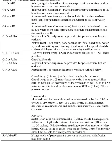
Table 5.6.1 Recommended pretreatment measures 45
Table 5.8.1 Mulch layer requirements 51
Table 5.9.1 Planting layer requirements 52
Table 5.12.1 Drainage layer requirements 72
Table 5.13.1 Nitrogen removal zone recommendations 76
Table 5.14.1 Recommended methods for calculating the infiltration
rate of a bioretention basin 79
Table 5.16.1 Inspection requirements 83
Table 5.17.1 Impervious liner requirements 84
Table 5.18.1 Groundwater considerations 88
Table 5.19.1 Bypass system requirements 90
Table 5.20.1 Kerb inlet design requirements 93
Table 5.21.1 Traffic lane flow width checking procedure recommendations 94
Table 5.22.1 Inlet scour requirements 95
Table C.1 Summary of recommended filter media requirements from the
guidelines reviewed 136
Table C.2 Summary of recommended filter media requirements from the
studies reviewed 142
Table D.1 Transition layer requirements 144
Table E.1 Perforated underdrain design requirements from publications
List of appendices
Appendix A 131
Appendix B 132
Appendix C 136
Appendix D 144
Nomenclature
TSS Total Suspended Solids
TN Total Nitrogen
TP Total Phosphorus
O/G Oil and Grease
WSUD Water Sensitive Urban Design
LID Low Impact Development
SUDS Sustainable Urban Drainage Systems
PVC Polyvinyl Chloride
AG Agricultural
Chapter 1 Introduction and overview
1.1.
Introduction
This study seeks to compare existing bioretention basin design guidelines, along with any studies on bioretention basin performance, to develop a ‘best practice’ design guideline. An appropriate naming convention for bioretention systems will also be sought as consistency is lacking in various publications. It will focus on urban stormwater drainage systems.
Storm runoff is directed in bioretention basins by gravity. Bioretention basins detain and treat the storm runoff to remove pollutants. They consist of a vegetated area with a fine media layer underneath which filters the runoff as it percolates downwards. Underdrains, at the bottom of the basin, collect the treated runoff and transport it into the constructed stormwater conveyance system. It eventually discharges to receiving waterways downstream (Brisbane City Council 2005a).
Bioretention basins are a relatively new system of stormwater drainage treatment and detention. They have simultaneously evolved in different ways and with different names at various locations around the world (Minton 2007). Inconsistency in their naming convention therefore exists.
1.2.
Background
1.2.1 Urbanisation impacts
In the natural environment, the discharge of storm runoff to the downstream receiving body is more gradual than in the urbanised environment. Infiltration, biological uptake, transpiration and evaporation reduce the amount of runoff in natural systems. Groundwater is recharged through percolation to aquifers. Around 70% of the runoff ends up as atmospheric moisture (Argue & Hogan n.d.).
Increased impervious area results in a reduction in infiltration, biological uptake, transpiration and evaporation. This causes an increase in the quantity of runoff (Victoria Stormwater Committee 1999). Pipes and channels convey this increased quantity of runoff much faster than it would be conveyed in a natural system, resulting in a reduction in lag time (time between peak rainfall and peak discharge at outfall). Peak flows in receiving waterways increase along with scour and erosion (Argue & Hogan n.d.). Frequency of high flow events also increases. The morphology of creeks and rivers can be altered as a result (ed. Wong 2006). More regular high flow events can also degrade the aquatic ecology by destroying habitat. Refer to Figure 1.1 for a flood hydrograph showing lag time.
Figure 1.1 Flood hydrograph lag time
(BBC 2008, p. 1)
downstream. These pollutants include nutrients, heavy metals and sediment which can have significant adverse impacts on waterways (Argue & Hogan n.d.).
Sediment can increase turbidity in water bodies, reduce the usefulness of the water and destroy ecological habitats (Davis & Cornwell 1998).
Toxic metals can become concentrated in the food chain and degrade the ecology (Davis & Cornwell 1998).
Nutrients of primary concern are nitrogen and phosphorus. In water bodies, excessive amounts can lead to algal blooms which deplete oxygen in the water body as they die and decompose. Organic suspended solids can also increase oxygen demand on a water body, adversely impacting on the ecology (Davis & Cornwell 1998). Eutrophication can be a result of increased nutrient load in waterways.
1.2.2 Water sensitive urban design (WSUD)
Water sensitive urban design (WSUD) seeks to minimise changes to the natural hydrological system through retention and detention of storm runoff at its source (Victoria Stormwater Committee 1999). Pollutant removal is also an aim of WSUD. Pervious areas of a catchment behave the same after development as before development, therefore only impervious areas of catchments need to be managed (Argue & Hogan n.d.).
WSUD results in a runoff hydrograph that is similar before and after development. Detention and retention of storm runoff before it enters the constructed storm water conveyance system lessen peak flows. With the implementation of WSUD the size of the constructed system’s elements can therefore be reduced saving costs (Victoria Stormwater Committee 1999).
Treatment of runoff at its source is a viable means of protecting receiving waterways from the adverse environmental impacts of pollutants. Vegetated swales and other WSUD systems filter pollutants and facilitate infiltration (Victoria Stormwater Committee 1999).
There also exist similar systems overseas. WSUD is known as Low Impact Development (LID) in the USA. Sustainable Urban Drainage Systems (SUDS) is the UK term. Hager (2003) describes LID as a stormwater management approach that treats rainfall on-site to attempt to maintain hydrological function. Neil Weinstein (cited in Hager 2003), executive director of the Low Impact Development Center in Beltsville, MD, describes LID as a "distributed source-control approach designed to treat and manage runoff at the source."
Some WSUD elements currently in use include:
• bioretention basins;
• bioretention swales;
• sand filters;
• sediment basins; and
• wetlands.
1.2.3 Bioretention basins
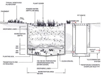
Bioretention basins use the processes of filtration, detention and biological uptake to remove sediments, nutrients and other pollutants (Melbourne Water 2005). Refer to Figure 1.2 for a typical section through a bioretention basin. Refer to Figures 1.3 and 1.4 for photographs of bioretention basins located in Melbourne.
Bioretention basins usually consist of a top layer of vegetation where water is ponded in a storm. The vegetation aids in preventing erosion. Its roots break up the soil, improved by wind blowing on the plants causing sway and movement in the roots. This aids in maintaining the desired hydraulic conductivity of the media below and preventing clogging of the system (Melbourne Water 2005). Biofilms on its roots absorb some pollutants. Temporary ponding increases the volume of treated runoff (Gold Coast City Council 2007).
The storm runoff then filters through several layers of different media, where pollutants are removed through filtration and other means, to slotted underdrains below. It is then conveyed to the conventional piped storm water system. Exfiltration from the bioretention basin to the surrounding soil can be encouraged if desired.
An overflow or bypass system is incorporated for high flows. This may be in the form of a grated pit with a cover level a few hundred millimetres above the surface of the bioretention basin or an overflow along a kerb and channel to a side-entry pit, if the basin is located alongside a roadway (Melbourne Water 2005).
The shape and size of bioretention basins is very adaptable so they can be used in a variety of locations. Clogging, however, can occur if exposed to certain materials, for example excess silt from a construction site (Melbourne Water 2005).
Figure 1.2 Bioretention basin typical section
[image:20.595.129.477.78.336.2](URS Australia Pty Ltd 2004, p. 5-31)
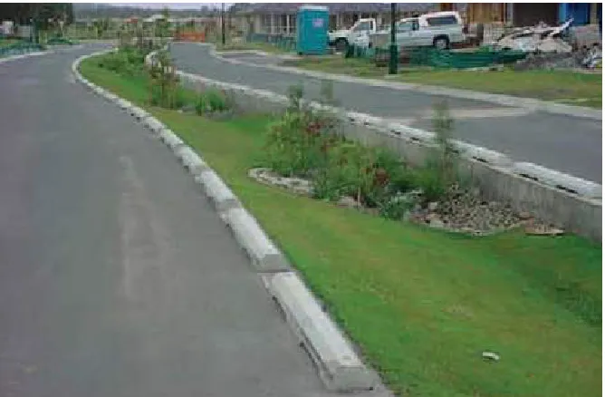
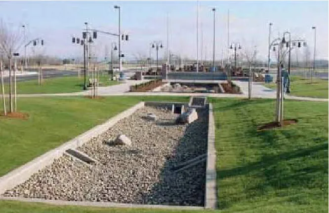
Figure 1.3 Photograph of a bioretention basin in Melbourne
Figure 1.4 Photograph of a bioretention basin in Melbourne
(Melbourne Water 2005, p. 17)
Bioretention basins have been shown to cause substantial reductions in peak flows, with a study by the Facility for Advancing Water Biofiltration (2008a) resulting in between 80 % and 86 % reduction. Evapotranspiration contributes to this reduction by around 20 % to 30 % depending on climatic factors.
Bioretention basins have the advantage over some other WSUD systems of being able to fit in relatively small spaces and being able to take on various shapes (Department of Water and Swan River Trust 2007). This makes them adaptable enough to be incorporated into roadside verges, median strips and parkland areas.
Bioretention is so-called as biomass is introduced to absorb and retain nutrients and other pollutants. Natural cleansing processes occur in the soil, mulch and vegetation areas of the bioretention basin (Prince George’s County 2002).
1.2.4 Bioretention swales
Figure 1.5 Photograph of a bioretention swale in Melbourne
(Melbourne Water 2005, p. 15)
1.2.5 Sand filters
Figure 1.6 Photograph of a sand filter located in Melbourne
(Melbourne Water 2005, p. 18)
1.3.
Project aims
This study aims to review and compare existing design guidelines for bioretention basins and establish a ‘best practice’ design guideline. Focus will be on bioretention basins adjacent to roadways and car parks. Studies will also be reviewed.
Some industry leaders claim there is an inadequate amount of literature on detailed design procedures for WSUD (ed. Argue 2004).
Currently there exist many design guidelines for bioretention basins. Several Australian states have their own, sometimes with many in each state. There also exist guidelines in other countries. These design guidelines use different approaches to design, essentially, the same systems.
The guidelines that will be considered are from:
Melbourne Water;
Brisbane City Council;
Upper Parramatta River Catchment Trust;
Gold Coast City Council;
Hobart City Council;
Moreton Bay Waterways and Catchments Partnership;
Department of Water and Swan River Trust;
Shire of Augusta, Margaret River;
Facility for Advancing Water Biofiltration, Monash University;
Prince George’s County, Maryland;
North Carolina State University;
California Stormwater Quality Association;
City of Reno; and
Several studies will be reviewed. They are:
Facility for advancing water biofiltration 2008a, Advancing the design of stormwater biofiltration, Monash University, Victoria.
Le Coustumer, S, Fletcher, TD, Deletic, A & Potter, M 2008, Hydraulic performance of biofilter systems for stormwater management: lessons from a
field study, Monash University, Victoria.
Hatt, BE, Fletcher, TD & Deletic, A 2007, ‘Hydraulic and pollutant removal performance of stormwater filters under variable wetting and drying regimes’, Water science and technology, vol. 56, no. 12, pp. 11-19.
Hatt, BE, Fletcher, TD & Deletic, A 2008, ‘Hydraulic and pollutant removal performance of fine media stormwater filtration systems’, Environmental science and technology, vol. 42, no. 7, pp. 2535-2541.
Le Coustumer, S, Fletcher, TD, Deletic, A & Barraud, S 2007, ‘Hydraulic performance of biofilters for stormwater management: first lessons from both laboratory and field studies’, Water Science & Technology, vol. 56, no. 10, pp. 93-100.
Bratieres, K, Fletcher, TD, Deletic, A & Zinger, Y 2008, ‘Nutrient and sediment removal by stormwater biofilters: A large-scale design optimisation study’, Water Research (2008), doi:10.1016/j.watres.2008.06.009.
Read, J, Wevill, T, Fletcher, T & Deletic, A 2008, ‘Variation among plant species in pollutant removal from stormwater in biofiltration systems’, Water Research, vol. 42, pp. 893-902.
Sharkey, LJ 2006, The performance of bioretention areas in North Carolina: a study of water quality, water quantity and soil media, North Carolina State
Hunt, WF, Jarrett, AR, Smith & Sharkey, LJ 2006, ‘Evaluating bioretention hydrology and nutrient removal at three field sites in North Carolina’, Journal of irrigation & drainage engineering, vol. 132, no. 6, pp. 600-608.
Hunt, WF, Smith, JT, Jadlocki, SJ, Hathaway, JM & Eubanks, PR 2008, ‘Pollutant removal and peak flow mitigation by a bioretention cell in urban Charlotte, N.C.’, Journal of Environmental Engineering, vol. 134, no. 5, pp. 403-408.
Hsieh, C & Davis, A 2005, ‘Evaluation and optimization of bioretention media for treatment of urban storm water runoff’, Journal of Environmental Engineering, vol. 131, no. 11, November, pp. 1521-1531.
Hong, E, Seagren, EA & Davis, AP 2006, ‘Sustainable oil and grease removal from synthetic stormwater runoff using bench-scale bioretention studies’, Water Environment Research, vol. 78, no. 2, pp. 141-155.
Davis, AP, Shokouhian, M, Sharma, H & Minami, C 2006, ‘Water quality improvement through bioretention media: nitrogen and phosphorus removal’, Water Environment Research, vol. 78, no. 3, pp. 284-293.
Hunt III, WF 2003, Pollutant removal evaluation and hydraulic characterization for bioretention stormwater treatment devices, Pennsylvania State University,
1.4.
Specific objectives
The specific objectives of this study are outlined:
1. Research existing design guidelines for bioretention basins and studies into bioretention basin performance.
2. Undertake a literature review of this information.
3. Compare the different design guidelines and study findings.
4. Critically evaluate the different design guidelines and study findings.
5. Establish a ‘best practice’ design guideline for bioretention basins.
6. Submit an academic dissertation including:
• An overview of water sensitive urban design and stormwater treatment
measures.
• An overview of the different bioretention basin design guidelines,
comparing their basis, and studies into bioretention basin performance.
• A critical evaluation of the different design guidelines and studies.
• A definition of a bioretention basin.
• A best practice design guideline for a bioretention basin.
• Recommendations for further research.
1.5.
Methodology
This study aims to investigate the different existing design guidelines and critically evaluate them. It is a desk-top analysis. Each design aspect of a bioretention basin is identified, compared and evaluated. Studies into bioretention basins are considered. A critical evaluation is conducted. A ‘best practice’ design guideline is concluded.
An overview of WSUD is researched in published literature and on the internet. Organisations involved in WSUD are used as sources of knowledge. Guidelines published by various authorities, including water authorities, local councils and stormwater organisations, are sourced on the internet. These are readily available. Published literature is also readily available.
Many different bioretention basin design guidelines exist. It is important to be able to compare each of these using a theoretical analysis. The design procedures will be divided into categories for ease of comparison. Comparison and critical evaluation would be difficult otherwise. These categories are:
catchment area requirements;
design flows establishment procedure;
detention volume establishment procedure;
depth of ponding requirements;
sizing of basin surface area;
pretreatment measures;
vegetation specification;
mulch layer design procedure;
filter media design procedure;
transition layer design procedure;
drainage layer design procedure;
nitrogen removal zone design procedure;
infiltration rate of system calculation procedure;
perforated underdrain design requirements;
inspection requirements;
impervious liner requirements;
groundwater considerations;
bypass system requirements and design procedure;
inlet design procedure;
traffic lane flow widths checking procedure;
inlet scour requirements; and
scour across vegetation layer checking procedure.
Research is conducted into the performance of bioretention basins. This is necessary to evaluate the different design guidelines. Research is sought from books and scientific journals as well as from stormwater and engineering organisations.
With different guidelines on their design, varying naming conventions for bioretention basins also exist. These are compared, along with any available literature on naming conventions, and critically evaluated to establish the most appropriate name for the system. An appropriate naming convention should be established for use across the whole industry. This would avoid confusion.
Chapter 2 Bioretention basin publications reviewed
Twelve design guidelines and twelve studies on bioretention basins are reviewed in this study. These are outlined below and their bases noted.
2.1.
Name of publication
For simplification, each publication is given a code number.
The format for the code number is,
XN-YZ-Country,
where,
X represents whether the document is a guideline (G) or a study (S).
N represents an identification number.
Y represents whether the publication is by an authority, organisation or government (A)
or by a university (U).
Z represents the university the publication may be affiliated with. It is omitted if it is a
publication by an authority as there is only one publication by each used in this study. There is often more than one publication affiliated with a particular university, however. This notation highlights which publications have come from the same university or people associated with that university, where,
M represents Monash University,
N represents North Carolina State University
R represents University of Maryland
P represents Pennsylvania State University, and
L represents University of Lyon.
Country is denoted AUS for Australia, USA for USA and AUS/F for Australia and France together.
Tables 2.1.1 and 2.1.2 outline the codes for each publication. These are then used throughout this document.
Table 2.1.1 Publications (guidelines)
Code Publication
G1-A-AUS Melbourne Water 2005, WSUD engineering procedures: stormwater,
CSIRO publishing, Collingwood.
G2-A-AUS Brisbane City Council 2005a, Draft Water Sensitive Urban Design
Engineering Guidelines: Stormwater, City Design, Fortitude Valley,
Queensland.
G3-A-AUS URS Australia Pty Ltd 2004, Water sensitive urban design technical
guidelines for Western Sydney, Upper Parramatta River Catchment
Trust (UPRCT), Parramatta.
G4-A-AUS Gold Coast City Council 2007, Water Sensitive Urban Design (WSUD)
Guidelines, Gold Coast City Council, Queensland.
G5-A-AUS Hobart City Council 2006, Water sensitive urban design site
development guidelines and practice notes, Hobart City Council,
Tasmania
G6-A-AUS Moreton Bay Waterways and Catchments Partnership 2006, Water sensitive urban design technical design guidelines for South East
Queensland, Healthy Waterways, South East Queensland.
G7-A-AUS Department of Water and Swan River Trust 2007, Structural controls,
stormwater management manual for Western Australia, Department of
Water and Swan River Trust, Perth, Western Australia.
G8-A-AUS Shire of Augusta – Margaret River 2006, Council’s standards and
specifications for subdivisions and developments, Shire of Augusta –
Margaret River, Western Australia.
G9-UM-AUS Facility for advancing water biofiltration 2008b, Guidelines for soil
filter media in bioretention systems, Version 2.01, Monash University,
Victoria.
G10-A-USA Prince George’s County, Maryland 2002, Bioretention manual, Prince George’s County, Maryland, USA.
Prince George’s County, Maryland n.d., Bioretention design
specifications and criteria, Prince George’s County, Maryland, USA
G11-UN-USA North Carolina State University, Stormwater Engineering Group 2001,
Designing rain gardens (bio-retention areas), North Carolina State
University, USA
G12-A-USA California stormwater quality association 2003, California stormwater
BMP handbook, new development and redevelopment, California
stormwater quality association, USA
G13-A-USA Kennedy/Jenks Consultants 2004, Truckee Meadows structural
controls design manual, City of Reno, USA.
G14-A-USA Hunt, WF & Lord, WG 2006, Bioretention performance, design,
construction, and maintenance, North Carolina Cooperative Extension
Table 2.1.2 Publications (studies)
Code Publication
S1-UM-AUS Facility for advancing water biofiltration 2008a, Advancing the design of
stormwater biofiltration, Monash University, Victoria.
S2-UM-AUS Le Coustumer, S, Fletcher, TD, Deletic, A & Potter, M 2008, Hydraulic performance of biofilter systems for stormwater management: lessons from
a field study, Monash University, Victoria.
S3-UM-AUS Hatt, BE, Fletcher, TD & Deletic, A 2007, ‘Hydraulic and pollutant removal performance of stormwater filters under variable wetting and drying regimes’, Water science and technology, vol. 56, no. 12, pp. 11-19. S4-UM-AUS Hatt, BE, Fletcher, TD & Deletic, A 2008, ‘Hydraulic and pollutant
removal performance of fine media stormwater filtration systems’,
Environmental science and technology, vol. 42, no. 7, pp. 2535-2541.
S5-UM/L-AUS/F Le Coustumer, S, Fletcher, TD, Deletic, A & Barraud, S 2007, ‘Hydraulic performance of biofilters for stormwater management: first lessons from both laboratory and field studies’, Water Science & Technology, vol. 56, no. 10, pp. 93-100.
S6-UM-AUS Bratieres, K, Fletcher, TD, Deletic, A & Zinger, Y 2008, ‘Nutrient and sediment removal by stormwater biofilters: A large-scale design optimisation study’, Water Research (2008),
doi:10.1016/j.watres.2008.06.009
S7-UM-AUS Read, J, Wevill, T, Fletcher, T & Deletic, A 2008, ‘Variation among plant species in pollutant removal from stormwater in biofiltration systems’,
Water Research, vol. 42, pp. 893-902.
S8-UN-USA Sharkey, LJ 2006, The performance of bioretention areas in North
Carolina: a study of water quality, water quantity and soil media, North
Carolina State University, USA
S9-UN-USA Hunt, WF, Jarrett, AR, Smith & Sharkey, LJ 2006, ‘Evaluating bioretention hydrology and nutrient removal at three field sites in North Carolina’,
Journal of irrigation & drainage engineering, vol. 132, no. 6, pp. 600-608.
S10-UN-USA Hunt, WF, Smith, JT, Jadlocki, SJ, Hathaway, JM & Eubanks, PR 2008, ‘Pollutant removal and peak flow mitigation by a bioretention cell in urban Charlotte, N.C.’, Journal of Environmental Engineering, vol. 134, no. 5, pp. 403-408.
S11-UR-USA Hsieh, C & Davis, A 2005, ‘Evaluation and optimization of bioretention media for treatment of urban storm water runoff’, Journal of Environmental
Engineering, vol. 131, no. 11, November, pp. 1521-1531.
S12-UR-USA Hong, E, Seagren, EA & Davis, AP 2006, ‘Sustainable oil and grease removal from synthetic stormwater runoff using bench-scale bioretention studies’, Water Environment Research, vol. 78, no. 2, pp. 141-155. S13-UR-USA Davis, AP, Shokouhian, M, Sharma, H & Minami, C 2006, ‘Water quality
improvement through bioretention media: nitrogen and phosphorus removal’, Water Environment Research, vol. 78, no. 3, pp. 284-293. S14-UP-USA Hunt III, WF 2003, Pollutant removal evaluation and hydraulic
characterization for bioretention stormwater treatment devices,
2.2.
Basis of publication
[image:34.595.101.529.123.568.2]Some guidelines reviewed state their bases. These are summarised in Table 2.2.1.
Table 2.2.1 Bases of guidelines reviewed
G1-A-AUS Not known
G2-A-AUS WSUD Engineering procedures: stormwater (Melbourne Water guidelines) G3-A-AUS (ARC 2003), Stormwater Management Devices: Design Guidelines Manual,
Revision of Technical G4-A-AUS Not known
G5-A-AUS WSUD Engineering procedures: stormwater (Melbourne Water guidelines) and Water Sensitive Planning for the Sydney Region (Upper Parramatta River Catchment Trust and others).
G6-A-AUS Water Sensitive Urban Design Engineering Guidelines: Stormwater (Brisbane City Council guidelines which are based on Melbourne Water guidelines) and Water Sensitive Urban Design Technical Guidelines for Western Sydney (Upper Parramatta River Catchment Trust).
G7-A-AUS Cooperative Research Centre for Catchment Hydrology 2003, Model for Urban Stormwater Improvement
Conceptualisation (MUSIC) User Guide, Version 2.0, December 2003.
Davis, A.P., Shokouhian, M., Sharma, H. and Minani, C. 1998, Optimisation of Bioretention for Design
for Water Quality and Hydrologic Characteristics, Final Report to Prince
George’s County, Maryland, United States of America. G8-A-AUS Not known
G9-UM-AUS Facility for advancing water biofiltration 2008a, Advancing the design of
stormwater biofiltration, Monash University, Victoria. This includes results from
studies undertaken on biofiltration systems.
Contributions by Melbourne Water Corporation, Dr Nicholas Somes
(Ecodynamics), Alan Hoban (SEQ Healthy Waterways Partnership), and STORM Consulting.
G10-A-USA Field experience, literature research, experimentation, and professional collaboration with individuals.
G11-UN-USA Not known G12-A-USA Not known G13-A-USA Not known
G14-A-USA North Carolina State University, Stormwater Engineering Group 2001, Designing
rain gardens (bio-retention areas), North Carolina State University, USA.
Research by North Carolina State University (on-site monitoring).
It is difficult to compare the bases of the various guidelines. Many of them do not state their bases. It is noted that four of the guidelines state a basis on Melbourne Water’s guidelines (G1-A-AUS). As they are all published by respected sources they all have some merit.
Table 2.2.2 Bases of studies reviewed
S1-UM-AUS On-site monitoring and laboratory experiments. S2-UM-AUS On-site monitoring and laboratory experiments. S3-UM-AUS Laboratory experiments.
S4-UM-AUS Laboratory experiments.
S5-UM/L-AUS/F On-site monitoring and laboratory experiments. S6-UM-AUS Laboratory experiments.
S7-UM-AUS Laboratory experiments.
S8-UN-USA On-site monitoring and laboratory experiments. S9-UN-USA On-site monitoring.
S10-UN-USA On-site monitoring.
S11-UR-USA On-site monitoring and laboratory experiments. S12-UR-USA Laboratory experiments.
S13-UR-USA On-site monitoring and laboratory experiments. S14-UP-USA On-site monitoring and laboratory experiments.
Chapter 3 Identification of a bioretention basin
The existence of various names for a bioretention basin means that care must be taken when selecting publications to review. It must be ensured that they focus, indeed, on the same system.
A comparison of the publications is undertaken reviewing the name of the system, physical elements included in it and pollutants removed.
[image:36.595.106.514.395.600.2]Table 3.1 outlines the various names used in each guideline reviewed. All systems either include the word ‘bioretention’ in their naming convention for the system or ‘rain garden.’ Those that include the word ‘bioretention’ in their name call the system a basin, system, facility, column, area or cell. G12-A-USA also refers to the system as ‘bioretention best management practice.’
Table 3.1 Name of system in guidelines reviewed
G1-A-AUS Bioretention basin. G2-A-AUS Bioretention basin.
G3-A-AUS Non-conveyance (off-line) bioretention system. G4-A-AUS Bioretention basin.
G5-A-AUS Bioretention system or rain garden (usually designed as a landscape feature).
G6-A-AUS Bioretention basin. G7-A-AUS Bioretention basin. G8-A-AUS Bioretention basin. G9-UM-AUS Bioretention system.
G10-A-USA Bioretention facility or bioretention column, rain garden describes small bioretention inside allotment.
G11-UN-USA Rain garden.
G12-A-USA Bioretention best management practice (BMP), bioretention area/cell/system/facility
G13-A-USA Bioretention system. G14-A-USA Bioretention cell/rain garden
Table 3.2 Name of system in studies reviewed
S1-UM-AUS Bioretention basin. (Bioretention systems include bioretention swales and bioretention basins).
S2-UM-AUS Biofiltration system (biofilter). S3-UM-AUS Bioretention system (biofilter).
S4-UM-AUS Fine media stormwater filtration systems,
Biofiltration systems/rain gardens (if systems are vegetated). S5-UM/L-AUS/F Biofiltration/bioretention system (biofilter).
S6-UM-AUS Biofiltration system/biofilters/rain gardens S7-UM-AUS Biofiltration system.
S8-UN-USA Bioretention cell S9-UN-USA Bioretention area S10-UN-USA Bioretention cell. S11-UR-USA Bioretention facility
S12-UR-USA Bioretention facility, bioretention system. S13-UR-USA Bioretention area.
S14-UP-USA Bioretention cell, Bioretention stormwater treatment device
In this study a bioretention basin is defined as a system that includes vegetation, filter media, underdrains and a drainage layer. It at least removes TSS, TP, TN and metals by means of filtration, absorption and biological uptake (and possibly other means).
Table 3.3 Physical elements included in system for each publication reviewed Grass buffer strip Vegetation Organic or mulch layer Planting layer Filter media Transition layer or geotextile fabric Drainage layer Nitrate removal zone Perforated underdrains Impervious liner Pervious filter fabric (around) Sand layer (along walls of system) Bypass system
G1-A-AUS 9 9 9 9 9 9 9
G2-A-AUS 9 9 9 9 9 9 9
G3-A-AUS 9 9 9 9 9 9 9 9
G4-A-AUS 9 9 9 9 9 9 9
G5-A-AUS 9 9 9
G6-A-AUS 9 9 9 9 9 9 9
G7-A-AUS 9 9 9 9 9 9 9
G8-A-AUS 9 9 9 9 9 9
G9-UM-AUS 9 9 9 9 9
G10-A-USA 9 9 9 9 9 9 9 9 9 9
G11-UN-USA 9
G12-A-USA 9 9 9 9 9 9
G13-A-USA 9 9 9 9 9 9
G14-A-USA 9
S1-UM-AUS 9 9 9 9 9 9 9
S2-UM-AUS
S3-UM-AUS 9 9 9 9
S4-UM-AUS 9 9 9 9
S5-UM/L-AUS/F 9 9
S6-UM-AUS 9 9 9 9 9 9
S7-UM-AUS 9 9 9
S8-UN-USA 9 9 9 9 9 9 9 9
S9-UN-USA 9 9 9 9
S10-UN-USA 9 9 9 9
S11-UR-USA 9 9 9 9 9 9
S12-UR-USA 9 9 9
S13-UR-USA 9 9 9 9 9
Table 3.4 Pollutants removed by system in each publication reviewed
Pollutants Litter/
debris
Organic matter
Small particles
TSS TP TN Nutrients Nitrates Ammo-nium
Hydro-carbons
O/G Metals Bacteria Pathogens
G1-A-AUS 9 9 9
G2-A-AUS 9 9 9
G3-A-AUS 9 9 9
G4-A-AUS 9
G5-A-AUS 9 9 9
G6-A-AUS 9 9 9
G7-A-AUS 9 9 9 9 9
G8-A-AUS 9 9
G9-UM-AUS
G10-A-USA 9 9 9
G11-UN-USA 9 9 9 9 9 9 9
G12-A-USA 9 9 9 9 9 9
G13-A-USA 9
G14-A-USA 9 9 9 9 9 9
S1-UM-AUS 9 9 9 9 9
S2-UM-AUS
S3-UM-AUS 9 9 9 9
S4-UM-AUS 9 9 9 9
S5-UM/L-AUS/F
S6-UM-AUS 9 9 9 9
S7-UM-AUS 9 9 9 9
S8-UN-USA 9 9 9 9 9 9
S9-UN-USA 9 9 9 9
S10-UN-USA 9 9 9 9 9 9 9
S11-UR-USA 9 9 9 9 9 9 9
S12-UR-USA 9 9 9
S13-UR-USA 9 9 9 9
Table 3.5 Means ofpollutant removal by system in each publication reviewed
Physical processes Filtratio
n Abs o rp -ti on B iol ogi cal upt ak e Extende d d eten tion Sedi me nt -at ion
Chemical processes Nitrifi- cat
ion Den itrifi -cat ion Vo latis-at
ion Ion
excha n ge Decomp- osi ti on Deg ra d a-ti on Phytore- medi at io n Bio remed i at ion
Thermal atten
u a-ti on Su nl ight & dry ing Precipita-ti on Surface complexa -ti on Eva pot ra n -spi rat ion B iot rans -fo rmatio n Othe r
G1-A-AUS 9 9 9
G2-A-AUS 9 9 9
G3-A-AUS 9 9 9
G4-A-AUS 9 9 9
G5-A-AUS 9 9 9
G6-A-AUS 9 9 9
G7-A-AUS 9 9 9 9
G8-A-AUS G9-UM-AUS
G10-A-USA 9 9 9 9 9 9 9 9 9 9 9 9 9
G11-UN-USA 9 9 9 9 9
G12-A-USA 9 9 9 9 9 9 9
G13-A-USA 9 9 9
G14-A-USA 9 9 9 9 9
S1-UM-AUS 9 9
S2-UM-AUS
S3-UM-AUS 9 9 9 9
S4-UM-AUS 9 9 9 9 9
S5-UM/L-AUS/F
S6-UM-AUS 9 9 9
S7-UM-AUS 9 9 9
S8-UN-USA 9 9 9 9 9
S9-UN-USA
S10-UN-USA 9 9
S11-UR-USA 9 9 9 9 9
S12-UR-USA 9 9 9 9
S13-UR-USA 9 9 9 9 9
Based on consensus, the main pollutants removed by bioretention basins are generally TSS, TP, TN and metals. TN and TP are nutrients so the ‘nutrients’ column needs consideration in conjunction with these. The main removal means are filtration, absorption and biological uptake. Sedimentation and degradation are also often listed as pollutant removal means.
For some studies, the elements listed are those that are described as being included in a bioretention basin. Not necessarily all elements were actually included in the experiments undertaken in these studies. In experiments, certain elements may have been singled out for testing. This comparison is simply to identify if they are studies on the same system. That is why this approach is taken.
For biological uptake to take place, vegetation is required. Without vegetation in a bioretention basin, there is no bioretention. Vegetation also keeps the filter media porous and enhances filtration (Brisbane City Council 2005a). This element must be included for the system to be considered a bioretention basin.
Most treatment in a bioretention basin is through fine filtration (Brisbane City Council 2005a). This occurs in the filter media layer, making this element necessary in a bioretention basin.
The general consensus is that bioretention basins are designed to collect the treated runoff for disposal at downstream waterways or at storage areas (Brisbane City Council 2005a). For this to occur, a drainage system is needed at the bottom of the basin. Perforated underdrains collect the treated runoff. A drainage layer is required to prevent clogging of these perforations (Hsieh & Davis 2005). These two elements are therefore crucial for the functioning of a bioretention basin. They must be included in a bioretention basin.
Only G12-A-USA includes a grass buffer strip in a bioretention basin. This is considered, therefore, to not be an element that defines the system.
nutrients to support the vegetation. Moisture may be maintained in the basin better with the inclusion of a mulch layer. Its provision is therefore subjective and up to the discretion of the designer. It is optional and is therefore not an element that must be included to define the system.
The planting layer also may aid the filter media in its functioning. Vegetation sustenance can be enhanced by its inclusion (URS Australia Pty Ltd 2004). It is considered optional (North Carolina State University, Stormwater Engineering Group 2001). This element is not necessary for inclusion to define a system as a bioretention basin.
The transition layer is required only if there exists the possibility of filter media migration into the drainage layer due to particle size distribution (Gold Coast City Council 2007). It is therefore optional and is not considered to be an essential element in defining a bioretention basin.
Only one guideline incorporates a nitrate removal zone in its bioretention basin (G14-A-USA). This guideline suggests that it appears to reduce total nitrogen. All the other publications that include a nitrate removal zone are studies, most undertaken in the last couple of years. This is a recent proposal and this element is not considered essential to define a bioretention basin.
Impervious liner is optional and depends on the objectives of the bioretention basin and the hydraulic conductivity of the in-situ soil (Department of Water and Swan River Trust 2007). A system which does not include impervious liner can still be considered a bioretention basin.
Only one guideline reviewed includes a pervious filter fabric around the walls of the bioretention basin (G12-A-USA). This is therefore considered optional.
not mean that one is not usually included. It is not considered a defining element in identifying the system in this case.
The elements that must be included to identify a system as a bioretention basin in the reviewed publications are vegetation, filter media, drainage layer and perforated underdrains. Guillette (2007) describes a bio-retention cell as a recessed landscaped area with a specialised soil mixture, an underdrain, vegetation and an aggregate base which is consistent with the definition found.
Twelve of the publications do not have all of these necessary elements listed. Most are studies rather than guidelines. Many of these studies do not give detailed descriptions and so some elements were simply not mentioned. It cannot be assumed that the description is not of a bioretention basin simply based on the elements omitted. These twelve publications are investigated further in order to identify them as bioretention basins or not.
G5-A-AUS, G12-A-USA, S3-UM-AUS, S7-UM-AUS and S13-UR-USA include the elements required except for the drainage layer. The systems described remove the main pollutants and use almost all of the pollutant removal mechanisms outlined as major. It is concluded that these publications describe bioretention basins.
Publications S12-UR-USA and S5-UM/L-AUS/F include the main elements except for the drainage layer and the perforated underdrains. The S12-UR-USA system removes most of the main pollutants and uses most of the main pollutant removal mechanisms and is identified as a bioretention basin. Publication S5-UM/L-AUS/F does not mention pollutants removed and mechanisms. Some of the authors of this study are affiliated with Monash University. Systems in other studies from Monash University (e.g. S1-UM-AUS) are already identified as bioretention basins therefore this system is assumed to be a bioretention basin also.
Publications S2-UM-AUS and S4-UM-AUS are also from Monash University. These are thus identified as bioretention basins by affiliation.
County Maryland include G10-A-USA, which is already identified as being on bioretention basins. Guideline G11-UN-USA is identified as a bioretention basin design guideline by association.
Guideline G14-A-USA does not list many physical elements in the system described. The system removes the four major pollutants by means of two of the main mechanisms. It is identified as a bioretention basin for the purposes of this study.
Study S10-UN-USA describes a system that does not include the four major elements outlined. One author is affiliated with study S9-UN-USA, which is identified as a bioretention basin study. Study S10-UN-USA is also identified as a bioretention basin by affiliation.
Chapter 4 Bioretention basin naming convention
Bioretention basins go by many names. They are also known as bioretention systems, bioretention cells, bioretention columns, bioretention facilities, biofiltration systems, biofilters, bioretention stormwater treatment devices, organic filters and rain gardens. In this study a bioretention basin is concluded to be a system that includes vegetation, filter media, underdrains and a drainage layer as a minimum. It at least removes TSS, TP, TN and metals by means of filtration, absorption and biological uptake (and possibly other means).
Minton (2007) expresses concerns that WSUD currently includes duplicative and badly-defined technical terms. He claims some treatment systems that are the same have names that are entirely different. Some systems that are different are known by the same name. He calls for a consistent naming convention.
In this study no publication was found with the name ‘bioretention’, ‘biofiltration’ or ‘rain garden’ that was not identified to be the same system. This conflicts with the views held by Minton (2007).
Guillette (2007) describes a rain garden as not having the same engineered features as a bioretention cell, such as the underdrains and specialised soil mixture. Only one publication reviewed referred to a bioretention basin as a rain garden it is therefore not considered an appropriate name for the system.
infiltration system (Minton 2007). This is also contrary to findings in this study. Darcy’s Law is used in all seven of the methods outlined in the reviewed publications for calculating the infiltration rate of the system and is concluded to be ‘best practice’ for the design of bioretention basins (refer to Section 5.14 for details). The claims of Minton (2007) appear unfounded.
Most publications reviewed in this study incorporate the word ‘bioretention’ in their naming convention for a bioretention basin. So what is bioretention? Plant roots uptake nutrients and metals from their host media. That means that bioretention occurs wherever plants exist. Minton (2007) claims that bioretention, therefore, is not exclusive to bioretention basins and also would occur in other WSUD systems including wet ponds and wetlands.
Minton (2007) proposes that bioretention should be considered as a mechanism of pollutant removal, such as filtration, flotation or sedimentation. Therefore, in his proposed naming convention, the terms bioretention and biofiltration are no longer used to refer to particular systems, but may be used to describe processes
Minton (2007) proposes a simplified system of categorisation of type and design criteria of treatment systems. He proposes a hierarchical system in which categorisation consists firstly of:
• family, being a group displaying common key characteristics of basins, swales,
filters, infiltrators and screens;
• then system, comprising a unit or several units;
• unit operation, being the processes that may occur in a single unit or part of a system, for example in a sand filter alone sedimentation and filtration occur;
• unit process, being the mechanism used in the process, eg. filtration, screening,
sedimentation, etc.; and
• principles, being the foundation of the processes used in the treatment,
categorised as either chemical, biological or engineering.
Milton (2007) proposes that those units in which the stormwater is infiltrated into the soil be called infiltrators (at least, when this is the main process of the unit). He proposes that a more accurate term for a bioretention basin be an infiltration cell as infiltration is its main function. This complies with the naming convention outlined earlier. Brisbane City Council (2005a) state that the filter media performs the majority of the pollutant removal in a bioretention basin through fine filtration and through supporting the vegetation, which enhances filtration and provides nutrient and contaminant uptake. Vegetation is therefore also a very important feature of a bioretention basin and the function of biological uptake is also. If a bioretention basin is referred to as an infiltration cell as per Minton’s suggestion, the name does not even insinuate that vegetation exists in the system. A sand filter could also be called an infiltration cell as filtration is its main function. Both systems cannot be described as such as they offer different applications and treatment mechanisms. On the other hand, the name bioretention basin does not suggest that fine filtration is the main function of the system either.
Only five of the twenty-eight publications in this study did not include the word ‘bioretention’ in the name given to describe a bioretention basin, meaning it is widely accepted. This is not as confusing and conflicting, therefore, as Minton claims.
Bioretention basins are sometimes referred to as ‘rain gardens’. Rain gardens, according to Hager (2003), consist of small depressions in individual lots to detain water and allow it to infiltrate. No special filter media is used. ‘Rain garden’ is not therefore an appropriate term for a bioretention basin.
Chapter 5 Bioretention basin design elements
The bioretention basin design procedure is divided into elements for ease of guideline and study comparison. Each of these elements is discussed in the following sections. The requirements outlined in various design guidelines are discussed as are the design recommendations of studies on bioretention basins. Each is analysed in an attempt to conclude a ‘best practice’ design procedure.
The design elements are outlined in the typical section of a bioretention basin shown in Figure 5.1.
5.1.
Catchment area requirements
The recommended size of catchment area for a bioretention system is outlined in Table 5.1.1.
Table 5.1.1 Recommended catchment area
G10-A-USA Catchment area should be limited to 1 to 2 acres. Preferred catchment area is less than 1 acre.
Catchment area is limited to one acre if underdrains are omitted. G12-A-USA Catchment area should be between 0.1 and 0.4 hectares (0.25 and 1.0
acres).
G13-A-USA Preferred catchment area is less than 1 acre.
Based on consensus a conservative recommendation for maximum catchment area for one bioretention basin is 0.4 hectares (1.0 acre).
5.2.
Design flows establishment procedure
The recommended methods for determining design flows for bioretention basins are outlined in Table 5.2.1.
Table 5.2.1 Design flow calculation method
G1-A-AUS Design flows found using the Rational Method.
G2-A-AUS Design flows found using the Rational Method, but for catchments greater than 50 ha runoff routing model is to be used.
G4-A-AUS Design flows found using the Rational Method, but for large catchments or if bioretention system is to form part of a retention basin a runoff routing model is to be used.
G6-A-AUS Design flows found using the Rational Method, but for large catchments or if bioretention system is to form part of a retention basin a runoff routing model is to be used.
5.3.
Detention volume establishment procedure
The methods of determining the detention volume for a bioretention basin in the reviewed publications are outlined in Table 5.3.1.
Table 5.3.1 Detention volume calculation method
G1-A-AUS The catchment area is modelled to determine the bioretention basin dimensions to meet pollutant removal objectives. Filter media characteristics are initially assumed. Local rainfall data should be used.
Modelling is performed using MUSIC (preferred), or design charts from MUSIC and regionalisation factors (if necessary).
G2-A-AUS The catchment area is modelled to determine the bioretention basin dimensions to meet pollutant removal objectives. Filter media characteristics are initially assumed. Local rainfall data should be used.
Modelling is performed using MUSIC (preferred), or design charts from MUSIC and regionalisation factors (if necessary). G3-A-AUS Determined using:
Vtreat = (ROD/1000) x A where,
Vtreat = Treatable volume (m3) ROD = Runoff Depth (mm) A = Catchment Area (m2)
For a capture period of 24 and 48 hour, and a capture rate of 60% of annual average runoff volume, the treatable volume per hectare to be provided are 150 m3/ha for a 24 hour period and 200 m3/ha for a 48 hour period.
Determined from:
Mean inter-event dry period (from rainfall data) of 24 hours to 48 hours, 60 % average annual rainfall volume filtration time through filter media. G4-A-AUS The catchment area is modelled to determine the bioretention basin dimensions to meet pollutant removal objectives. Modelling is performed
using MUSIC.
G10-A-USA Storage volume required is derived from a graph using existing and proposed runoff curve numbers. This volume is the volume of detention required to maintain the existing runoff volume leaving the site prior to development. The runoff curve numbers are calculated from pervious and impervious areas.
A chart is also used to derive the detention required to maintain the predevelopment peak runoff rate.
The desirable percentage of the site required to be used for bioretention is then storage required to maintain predevelopment peak runoff plus storage required to detain predevelopment runoff volume. If this is not achievable, only some of the predevelopment runoff volume is detained. G11-UN-USA The rain garden may be made large enough to accommodate the runoff from the first inch of rain on the catchment. The runoff depth is
calculated using a formula from the Natural Resources Conservation Service. This uses the CN value to calculate the runoff depth in the catchment from one inch of rain. The CN value is the curve number which is a measure of how much rain will infiltrate in the catchment. This is determined by soil type and land use (i.e. percentage of pervious and impervious areas) and is derived from a standard table.
Runoff depth in inches = (P - 0.2 S)2 )(P + 0.8 S), where, P = precipitation (typically use 1 inch) and, S = 1,000 ÷ CN – 10.
CN = Curve Number.
Runoff volume is then determined.
Runoff volume (cubic feet) = Area × Runoff depth
G12-A-USA Size should be such that design storm runoff may be captured.
G13-A-USA The Water Quality (WQV) method is used to determine the detention volume. This method is based on the following formulae:
WQV = [(P)(RV)(A)]/12, and,
RV = 0.05 + 0.009I
where,
WQV = water quality volume (ft3)
P = the 90th percentile precipitation depth (0.60 inches) RV = watershed runoff coefficient
I = percent of watershed impervious area A = drainage area (ft2)
There are various methods of calculating the required storage volume for a bioretention basin. Five out of nine publications focus on the pollutant removal objectives. Of these, four use a modelling approach. Four focus on capturing a certain amount of runoff.
MUSIC is an acronym for ‘Model for Urban Stormwater Improvement Conceptualisation.’ It is a conceptual design tool developed by Melbourne Water in Victoria, Australia. MUSIC is capable of estimating stormwater pollutant generation and the performance of stormwater treatment measures (Melbourne Water 2004). MUSIC can be used to determine the pollutant removal capabilities of stormwater treatment devices. Treatment objectives specified by Melbourne Water (2004) are;
45% reduction in total nitrogen (TN) from typical urban loads 45% reduction in total phosphorus (TP) from typical urban loads
80 % reduction in total suspended solids (TSS) from typical urban loads 70% reduction in litter from typical urban loads
Maintain discharges for the 1.5 year ARI event at pre-development levels.
These targets, however, may vary depending on the requirements for and nature of the receiving waterway downstream.
The guidelines reviewed that recommend the use of modelling for sizing bioretention basins recommend using MUSIC.
5.4.
Depth of ponding requirements
The methods of determining the ponding depth for a bioretention basin in the reviewed publications are outlined in Table 5.4.1.
Table 5.4.1 Ponding depth calculation method and requirements
G1-A-AUS The catchment area is modelled to determine the bioretention basin dimensions to meet pollutant removal objectives. Filter media characteristics are initially assumed. Local rainfall data should be used.
Modelling is performed using MUSIC (preferred), or design charts from MUSIC and regionalisation factors (if necessary).
G2-A-AUS The catchment area is modelled to determine the bioretention basin dimensions to meet pollutant removal objectives. Filter media characteristics are initially assumed. Local rainfall data should be used.
Modelling is performed using MUSIC (preferred), or design charts from MUSIC and regionalisation factors (if necessary).
G4-A-AUS The catchment area is modelled to determine the bioretention basin dimensions to meet pollutant removal objectives. Modelling is performed using MUSIC
Temporary ponding to be up to 300 mm deep over surface of filter media. This is controlled by the level of the overflow pit.
G6-A-AUS The catchment area is modelled to determine the bioretention basin dimensions to meet pollutant removal objectives. Modelling is performed using MUSIC
Temporary ponding to be up to 300 mm deep over surface of filter media. This is controlled by the level of the overflow pit.
G10-A-USA Preferred depth 76 mm (3 inches) to 102 mm (4 inches).
Maximum depth 152 mm (6 inches). Maximum may be increased as long as surface ponding dewaters in 3 to 4 hours so as to not limit potential plant species chosen.
G11-UN-USA Typically 229 mm (9 inches), but may be between 152 mm (6 inches) and 305 mm (12 inches). Deeper limits plant selection diversity.
G12-A-USA Maximum depth 152 mm (6 inches). This maximum is
recommended to not restrict plant selection. Surface ponding to dewater in 3 days to restrict breeding of mosquitos and other insects. G13-A-USA Maximum depth 152 mm (6 inches) (recommended). Surface
ponding to dewater in less than 7 days to prevent mosquito breeding.
The functions of surface ponding include; to slow flow velocity to reduce vegetation scour; to increase storage volume; and to ensure the ponded water is not a hazard to the public (Moreton Bay Waterways and Catchment Partnership 2006) as well as allowing time for evaporation and sedimentation (Pince George’s County, Maryland 2002).
three recommend a maximum depth of 152 mm (6 inches). Those that recommend a 152 mm (6 inches) maximum do so to prevent the diversity of plant selection from being diminished. The length of time for surface ponding dewatering affects the types of plants that may be suitable. G10-A-USA allows the depth to be increased as long as the surface ponding dewaters in 3 to 4 hours. The longer the time submerged, the less plant species can survive.
The treatable volume must be contained in the ponding depth and the surface area of the bioretention basin. Changing any of these design parameters affects the other two. The ponding depth must therefore be suitable to contain the volume to be treated.
5.5.
Sizing of basin surface area
[image:56.595.107.539.154.774.2]The recommended surface areas for a bioretention basin are outlined in Table 5.5.1.
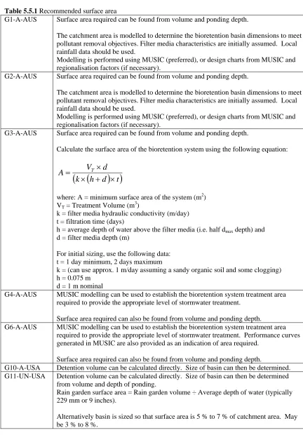
Table 5.5.1 Recommended surface area
G1-A-AUS Surface area required can be found from volume and ponding depth.
The catchment area is modelled to determine the bioretention basin dimensions to meet pollutant removal objectives. Filter media characteristics are initially assumed. Local rainfall data should be used.
Modelling is performed using MUSIC (preferred), or design charts from MUSIC and regionalisation factors (if necessary).
G2-A-AUS Surface area required can be found from volume and ponding depth.
The catchment area is modelled to determine the bioretention basin dimensions to meet pollutant removal objectives. Filter media characteristics are initially assumed. Local rainfall data should be used.
Modelling is performed using MUSIC (preferred), or design charts from MUSIC and regionalisation factors (if necessary).
G3-A-AUS Surface area required can be found from volume and ponding depth.
Calculate the surface area of the bioretention system using the following equation:
(
)
(
k h d t)
d V A T × + × × =
where: A = minimum surface area of the system (m2) VT = Treatment Volume (m3)
k = filter media hydraulic conductivity (m/day) t = filtration time (days)
h = average depth of water above the filter media (i.e. half dmax depth) and
d = filter media depth (m)
For initial sizing, use the following data: t = 1 day minimum, 2 days maximum
k = (can use approx. 1 m/day assuming a sandy organic soil and some clogging) h = 0.075 m
d = 1 m nominal
G4-A-AUS MUSIC modelling can be used to establish the bioretention system treatment area required to provide the appropriate level of stormwater treatment.
Surface area required can also be found from volume and ponding depth.
G6-A-AUS MUSIC modelling can be used to establish the bioretention system treatment area required to provide the appropriate level of stormwater treatment. Performance curves generated in MUSIC are also provided as an indication of area required.
Surface area required can also be found from volume and ponding depth.
G10-A-USA Detention volume can be calculated directly. Size of basin can then be determined. G11-UN-USA Detention volume can be calculated directly. Size of basin can then be determined
from volume and depth of ponding.
Rain garden surface area = Rain garden volume ÷ Average depth of water (typically 229 mm or 9 inches).
G12-A-USA Size should be such that design storm runoff may be captured.
Minimum size 12.2 m by 4.6 m (40 feet by 15 feet).
Facilities wider than 6.1 m (20 feet) should be twice as long as they are wide. G13-A-USA Detention volume can be calculated directly. Size of basin can then be determined.
Minimum size 12.2 m by 4.6 m (40 feet by 15 feet). Preferred size 15.2m by 7.6 m (50 feet by 25 feet).
Facilities wider than 6.1 m (20 feet) should be twice as long as they are wide (promotes distribution of flow and discourages concentrated flow).
S1-UM-AUS If basins are too small for their catchment or if the catchment has high silt loads surface clogging can occur.
Systems that are 4% the size of the impe