©
The Copyright of this paper is Reserved.
Mechatronics and Machine Vision 2003: Future Trends,
ed. J. Billingsley,
The Steering of Trailed Implements for Tractor Path
Tracking
Clement Ong,
College of Computer Studies
De La Salle University
2401 Taft Avenue, Manila 1004, Philippines
Professor John Billingsley,
Faculty of Engineering and Surveying
University of Southern Queensland
Toowoomba, QLD 4350 Australia
Abstract
In contour farming operations, it is important that the path of an implement
precisely follows the path of the tractor that pulls it. An alternative
implement positioning method is proposed that avoids the use of steered
coulters or wheels: unequal drag forces from differential dig depths of the
implement's wings linearly slews the rig, changing its path. The
experimental rig, an AFM-880 cultivator, has a span of 10m and a
drawbar length of 5m. It was found that position could be arbitrarilly set
versus the nominal center by as much as 48 cm if the wing heights were
caused to differ by 30 cm. The calibrated simulation of the uncontrolled,
natural path of a trailed rig on a sinusoidal path was compared with the
path generated when the rig was actively steered differentially, showing a
significant reduction in path undercut, a prerequisite to garnering the full
benefits of controlled traffic.
Keywords
Contour Farming, Controlled Traffic, Trailed Implement Steering
1. INTRODUCTION
Controlled traffic requires significant operator skill and concentration to keep farm equipment precisely positioned. Controlled traffic can, however, enhance the economic and environmental sustainability of agriculture, as permanent beds for optimum crop growth and compacted laneways for traffic and runoff control become realizable [5].
steer, guide or position the components of trailed rigs are few, often costly and can not be used for larger machinery.
For loose-hitched three-sectioned trailed implements, support wheels are fixed to rotate perpendicular to the breadth and parallel to the drawbar of the rig. Adapting such rigs to actively steer normally requires the addition of a set of rear coulters and phased steering rams, as well as some form of steering control. This study develops and investigates the viability of steering the rig to a desired position by generating unequal drag forces on opposing ends of the rig breadth. How this can be accomplished and how much movement can be expected from this approach is investigated.
2. COMPUTER MODEL 2.1 Unsteered Rig Kinematics
Loose-hitched rigs of medium-scale are constructed using three sections of equal size. The two outer sections are designed to be folded upward to reduce transport width, a necessity on public roads. In normal field work however, these sections use phased rams to ensure section heights (tyne depths) are the same. A single-beam or sometimes ‘A’-shapped drawbar connects the rig to a single, loosely-pinned hitchpoint at the rear of the tractor.
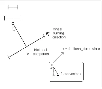
[image:3.595.206.386.432.588.2]A simplified schematic of a tractor and trailed rig is shown in Figure 1. Since wheels are always parallel with the drawbar, the wheels influence the rig to center on the tractor path, with a centering force proportional to the speed of the tractor and rig, and the sine of the angle made by the tractor to the drawbar.
Figure 1 Tractor and Rig Schematic
The force contributed by the wheels is:
(2.1.1)
where
US = Tractor speed
δ =Damping factor
Frictional forces developed by the action of implements being dragged in the soil are large however evenly distributed. If the heights of each section of the rig are equal, the friction forces through the breadth of the rig will be the same, in the direction as indicated in Figure 1. This force acts as a damping factor to any motion of the rig.
2.2 Differential Dig Influence
Slightly modifying the hydraulic connections to rams that control the height of each section of the rig allows the normally in-phase rams to work independently of each other. This allows the height of each section of the rig to become semi-independent of each other. Since it has been shown that the forces generated by digging rises linearly with depth [4], drag forces generated on each wing will be unequal if section heights are not equal. If the outer sections’ heights are differentially set against the center (i.e. in a three-sectioned rig, one wing’s height is set higher than that of the center wing, and the other wing is set lower than the center), the drag forces will be in one particular direction. This can influence the position of the rig as it is pulled, effecting a form of steering. The advantage of differential dig is that the modifications to the rig are minimal and the cost is likewise small, as it utilises existing components on the trailed implement.
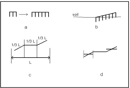
The influence of the differential dig action needs to be made into an equation. First, consider a simplified rig with a set of tynes spanning the width of the rig. It can be seen in Figure 1(a) that the larger the span of the rig, the greater the number of tynes it can accommodate. If the required force to draw the tynes are all the same, then the larger the span, the greater the total force required to draw the rig.
[image:4.595.187.404.480.626.2]A second simplifying assumption is that the force required is linearly proportional to depth, the effect of unequal dig depths represented by a diagonal span for the rig as shown in Figure 1(b), on the force would be proportional to the dig depth difference and the span of the rig. It is then possible to see that the total force generated varies with the square of the rig span.
Recalling that the rig is actually made up of three sections, the center of which does not participate in the differential dig process, the influence of the differential dig is reduced by a ratio of 2/3, representing the two outer sections’ action - Figure 1(c). However these are still hinged to the center unit, therefore the dig difference only represents the extremities of the difference in depth at the edges of the span. The average dig depth difference is only one-half of that, as shown in Figure 1(d), leaving a ratio of 2/3 * 1/2 = 1/3.
Finally it can be stated also that the dig depth difference should be ratioed against the overall depth of the center wing, which serves as a reference, i.e., the differential force will be a smaller percentage of the total force if the overall dig depth is large. The final equation for the effect of the tynes digging in differentially is modelled as a displacement in the drawbar pulling point on the rig, at the same time lumped with the overall shift of the rig from an arbitrary reference line:
(2.2.1)
where
Dd = Dig depth difference Dc = Depth of Centre Section Bo = Drawbar offset
Lr = Rig Span
The total force on the rig influencing its centre’s path versus that of the tractor is then:
(2.2.2)
where
k1 = Wheel influence factor
k2 = Tyne influence factor, due to differential dig
The computer simulation program based on these model equations appears in the Appendix. The equations are converted to discrete form and the tractor speed is made constant to simplify the simulation. Euler integration is used to generate the data for tractor and rig paths, and integration errors reduced by keeping the time step small.
F
L
D
D
B
T R
d
c O
∝
1
+
3
2
3. PROTOTYPE TESTS AND MODEL TUNING
The computer model of the rig must be initially tuned to reflect the actual nature of the physical trailed implement, which will vary with design. Experimental results of differential dig implementation on an Australian Farm Machinery model 880 cultivator were used as basis for setting up the simulation model.
3.1 Actual Rig Response from Off-Center Position
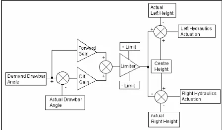
[image:6.595.182.406.314.446.2]A prototype system based on a Motorola MC68HC11 microcontroller was set up and integrated into an AFM-880 cultivator for testing. The cultivator’s hydraulics were modified to accommodate the differential movement of the left and right wings under linear-proportional control. Real-time data was gathered from the microcontroller and transmitted serially to the notebook computer, which then saved these as files. Figure 2 illustrates the control system effected by the combined notebook and microntroller programs.
Figure 2 Closed-loop linear control implemented on the prototype system
Figure 3 Slew response of rig, starting off-center
3.2 Trailed Rig Response to Step Change in Demand
Differential dig of 15.2cm causes the rig to move from the centre line, as actually measured on the rig by the drawbar angle of 5.5 degrees, shown in Figure 4. This shows the system is able to move approximately 48 cm from the center.
Figure 4 Trailed rig response to step change in demand
The influence of the rig wheels and differential dig on the position of the rig are set by parameters k1 and k2 in the computer model. They were interactively tuned to endow the model with the same slew rate, stability and influentiability by differential dig. The slew rate of the hydraulics controlling the wing depth, evidenced by the finite steepness of the trace was set also to reflect the limited speed on the actual rig, where the rate was limited by the size of the control valve tapped onto the hydraulic circuit of the tractor, as shown in Figure 5
Figure 5 Differential dig and rig positional skew tuning
4. CONTROL SYSTEM CHARACTERIZATION 4.1 Rig Position Jitter without Control
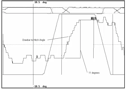
In order to characterise the drawbar angle without differential control, the tests were coducted with the differential dig control action off, and the tractor drawing the trailed rig in a normal, straight path. As the trailed implement was drawn over the uneven soil surface with the wings digging to a normal depth of 15.2 cm, readings of the drawbar angle were taken every 0.2 seconds. The resulting plot is shown in Figure 6. Top plot shows section demand movements, center plot shows drawbar angle versus tractor heading.
Figure 6 Drawbar to hitch angle jitter (center plot), differential dig off
4.2 Rig Position Jitter with Control
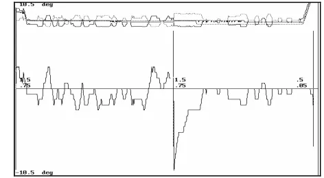
In the plot in Figure 7, the differential gain is 1.0. What appears to be some instability is show at the left group of plots, where at the 2/3 point of the run there is a marked increase in the peak-to-peak jitter readings. On subsequent runs however the jitter is reduced, and in some areas even eliminated. The large variations in drawbar angle 2/3 of the way on the first group plot may reflect uneven compaction (and drag) of the soil rather than instability of the differential dig.
[image:9.595.180.406.244.375.2]
Figure 7 Jitter control with differential dig, differential gain = 1.0
4.3 Rig Position Controllability
Combined feedforward and differential gain put into action is shown, with both set to nominal 1.0 values. The demand drawbar to hitch angle as the run begins is initially zero, then the rig is required to slew to one side then the other. The plots of demand and actual clearly correspond with each other in Figure 8. Top plot shows wing movements. Center plot shows drawbar angle versus tractor heading, the continuous line is the demand (required) angle, the dotted line is the actual angle.
[image:9.595.183.407.528.655.2]Since data from the prototype conclusively shows that the linear-proportional steering system can move the trailed implement to any desired position within its range, and with the model parameters tuned to that same level of performance, the simulation now focuses characterizing the system’s ability to maintain the trailed implement along a curved tractor path.
5. CURVED PATH SIMULATIONS 5.1 Differential Dig Inactive
[image:10.595.183.406.312.410.2]A path consisting of a +- 0.25 meter peak sinusoidal curve, over a distance of 38 meters is simulated. The tractor and rig begin with an offset of 0.1 meters from the reference path. In Figure 9, the differential dig control is inactive, producing a rig path that markedly undercuts the path of the tractor. The simulation has a total horizontal distance of 115 meters, vertical is 0.5 meters, peak to peak.
Figure 9 Tractor and rig response to curved path
5.2 Differential Dig Active
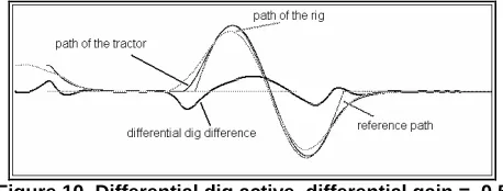
With the control system active in the simulation and a mild value set for the differential dig gain, rig position versus tractor path is plotted. Comparing Figure 9 with Figure 10, the intersection of the rig path with that of the tractor path already reflects a slight improvement in path tracking. The intersection point of these two lines has shifted to a later position showing a better correlation between paths.
Figure 10 Differential dig active, differential gain = 0.5
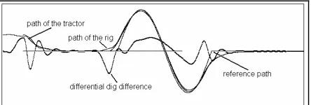
[image:10.595.180.409.522.609.2]path. The differential dig limits are not being reached however since the magnitude of the curve in the path is small.
Figure 11 Differential dig active, differential gain = 1.5
6. CONCLUSIONS
Steering of a trailed implement using differential drag forces generated by unequal dig depths has been implemented and characterised. The results show that in the case of the AFM rig, side-to-side jitter was reduced by a factor of three. A differential gain of approximately 2.5 cm of difference on each wing versus the center wing depth per degree of error produces the best results in trading excessive differential dig activity. A feedforward gain of 1.3 to 1.9 cm of dig depth difference per degree off-center from zero is adequate to move the rig to the approximate user requested angle, allowing arbitrary positioning of the rig centre against the path of a forward-moving tractor. For a 15.2 cm maximum depth difference, a peak offset from the path of +-5.5 degrees from a 5-meter drawbar, or +-48 cm, was attained. Using this data to tune a computer model, the simulations show that it should be possible to attain steering of the trailed implement and reduce its path tracking errors to +-1.5 cm on a sinusoidal path whose peak offsets are +-0.25m over a distance of 38 meters.
7. REFERENCES
[1] C Ong, J Billingsley, A Unique Approach to Steering of Trailed Implements for Tractor Path Tracking, Proceedings: 5th International Conference on Mechatronics Technology, National University, Singapore, June 2001
[2] J Billingsley, M Schoenfisch, Vision-Guidance of Agricultural Vehicles, Proceedings: National Controlled Traffic Conference, Rockhampton, Queensland, Sept 1995
[3] C Ong, Control and Instrumentation of Trailed Implements for Path Tracking, M Eng Thesis,University of Southern Queensland, 1999
[4] A Palmer, N Smith and P Smith, Forces of Chisel Plough Tines - A Field Study, Proceedings: Conference on Agricultural Engineering, Sept 1988, pp 64-88
APPENDIX
Tractor with Trailed Implement on Curved Path Simulation (QBASIC)
' Front Steering Tractor + Rig w/ Differential Dig Simulation
DECLARE FUNCTION pathfunc (z, mag) ' returns an offset value from a straight ' line that the tractor+rig should follow DECLARE SUB waitkey () ' pauses execution and waits for user go DECLARE FUNCTION lim! (a!, b!) ' returns a! if a! < b! else b!
CONST pi = 3.14159
CONST White = 15 ' color definitions for graphics display CONST BRed = 12
CONST BGreen = 10 CONST BBlue = 9
CONST tmax = 64 ' simulation time, in seconds CONST k1 = .85 ' Rig wheel influence factor CONST k2 = .005 ' Rig tyne influence factor
CONST speed = 1.78 ' metes per second, = 4 miles per hour CONST ltrac = 3 ' 3 meters from front wheels to rear wheels CONST lpivot = 1.2 ' 1.2 meters from rear wheels to hitch pt CONST lrig = 5 ' rig depth
CONST ldraw = 8 ' drawbar length
CONST steerate = 1 / 10 ' compliance rate of steering on tractor CONST focus = 1 ' length ahead of tractor that sensing of the path CONST gain1 = 1
CONST gain2 = 1 CONST gain3 = 1.2
CONST difgain = 1.5 ' differential dig gain CONST anglim = 1
CONST smax = .5 ' max steering value, +-
'CONST maxdig = .1524 ' maximum differential dig, 6 inches CONST maxdig = .0762 ' max dif dig is 3 inches...
'CONST maxdig = .0381
CONST curvemag = .25 ' magnitude of curve in path
CONST maxlag = 500 ' maximum number of path points to "remember" CONST lagcount = 450 ' actual lagged path points utilized by the controller
SCREEN 9 ' go graphics mode
WINDOW (-10, -.5)-(tmax * speed, .5) ' define graphic coordinate area LINE (0, 0)-(tmax, 0), 9
DIM SHARED xrig, vxrig, xtrac(maxlag), atrac, steer, dmax
dist = 0: time = 0: steer = 0: dmax = tmax * speed d0 = .0762 ' center wing dig depth, 3 inches dt = .01 ' simulation timer granularity
digrate = .1524 / 3.5 ' rig hydraulic lifters speed of compliance xtrac(maxlag) = xrig: atrac = 0
FOR ctr = 0 TO maxlag - 1
xtrac(ctr) = xtrac(maxlag) ' init path history to the NEXT ctr ' present offset from center line
ctr2 = ctr - lagcount ' point to path position where controller should sense path
DO
straightline = xtrac(ctr) + (ltrac + focus) * atrac path = pathfunc(dist + ltrac + focus, curvemag) feelpoint = straightline - path * gain3
angdemand = lim(-gain1 * feelpoint, anglim) steertarget = lim(gain2 * (angdemand - atrac), smax) valves = steertarget - steer
dsteer = SGN(valves) * steerate
datrac = steer * speed / ltrac 'tractor angle ref to straight line dxtrac = atrac * speed 'tractor distance from straight line xpivot = xtrac(ctr) - lpivot * atrac
targetdig = lim((xtrac(ctr2) - xrig) * difgain, maxdig) ctr2 = (ctr2 + 1) MOD maxlag
digerror = targetdig - dig ' dig is the present dig depth difference ddig = digrate * SGN(digerror)
' ddig = 0 'uncomment this line to show what happens without ' active steering on the rig...
dxrig = speed * vxrig 'rig distance to straight line dwheelrig = (((xpivot - xrig) / ldraw) * speed - vxrig) * k1
dtynerig = (dig * lrig ^ 2 / (3 * d0) + xrig - xpivot) * k2 dvxrig = dwheelrig + dtynerig
time = time + dt 'Euler integration dist = dist + speed * dt
dig = dig + ddig * dt xrig = xrig + dxrig * dt vxrig = vxrig + dvxrig * dt atrac = atrac + datrac * dt steer = steer + dsteer * dt
tempy = xtrac(ctr) + dxtrac * dt 'a queue is used to keep a ctr = (ctr + 1) MOD maxlag 'history of the tractor's path xtrac(ctr) = tempy 'which the rig will follow
PSET (dist + ltrac + focus, path), BRed ' plot path
PSET (dist, xtrac(ctr)), White ' plot tractor rear path PSET (dist - xpivot - ldraw, dig * 7), Bgreen ' plot differential dig PSET (dist - xpivot - ldraw, xrig), BBlue ' plot rig path
z$ = INKEY$
IF z$ <> "" THEN a$ = z$
LOOP UNTIL time > tmax OR a$ = "q"
FUNCTION lim (a!, b!)
END FUNCTION
FUNCTION pathfunc (z, mag) temp = z - dmax / 3
temp2 = z - dmax * 2 / 3
IF (temp < 0) OR temp2 > 0 THEN pathfunc = 0
ELSE
theta = 18 * pi * (temp / dmax / 3) pathfunc = mag * SIN(theta) END IF
END FUNCTION
SUB waitkey
WHILE INKEY$ = "" WEND