Electro Muscle Stimulus System for
Wasted Muscle Rehabilitation
A dissertation submitted by
David Dobson
In fulfilment of the requirements of
Courses ENG4111 and ENG4112 Research project
Toward the degree of
Bachelor of Engineering (Electrical)
perform at its prior functionality. Muscle degeneration can be a symptom of aging, injury, nerve damage, stroke, motor neuropathy, muscular dystrophy and arthritis in addition to many ailments.
Muscle degeneration impacts on the quality of life of those affected. To have a device which could stop or reverse muscle degeneration could have a significant impact on the quality of life for these people. Many who are affected by muscle degeneration experience barriers to undertaking strenuous exercise such as weights and resistance training. For these people, doing something as simple and unobtrusive as wearing an armband, would be advantageous in reducing recovery time or assisting with ongoing problems.
The purpose of this project is to test the ability of targeted Electrical Muscle Stimulation (EMS) to increase muscle strength by designing and testing an apparatus that can be worn on the forearm.
University of Southern Queensland
Faculty of Health, Engineering and Sciences
ENG4111/ENG4112 Research Project
Limitations of Use
The Council of the University of Southern Queensland, its Faculty of Health,
Engineering & Sciences, and the staff of the University of Southern Queensland, do
not accept any responsibility for the truth, accuracy or completeness of material
contained within or associated with this dissertation.
Persons using all or any part of this material do so at their own risk, and not at the
risk of the Council of the University of Southern Queensland, its Faculty of Health,
Engineering & Sciences or the sta
ff
of the University of Southern Queensland.
Certification
I certify that the ideas, designs and experimental work, results, analyses and conclusions set out in this dissertation are entirely my own effort, except where otherwise indicated and acknowledged.
I further certify that the work is original and has not been previously submitted for assessment in any other course or institution, except where specifically stated.
Student Name: David Dobson
Student Number:0061003544
Signature
Acknowledgements
I would like to take this opportunity to thank the following people:-
My wife, Amy, for her love, encouragement, support and understanding – and of course her amazing proofreading and editing skills.
Dr Les Bowtell for his advice and supervision throughout this project. Terry Byrne for his sense of humour and constant stream of sarcasm. Graham Holmes for the never ending supply of parts and components.
Table of Contents
Abstract ... i
Certification... iii
Acknowledgements ... iv
List of figures ... vii
List of tables ... viii
Nomenclature and Acronyms ... ix
1 Task ... 1
2 Background ... 1
3 Objectives... 3
3.1 Research the background information on muscles required for hand control, anatomy ... 3
3.2 Research the background on EMS and the control of muscles, voltage levels, optimum electrode area and shape, optimum electrode material and position placement on the forearm. ... 9
3.3 Critically examine techniques and choose a method which best meets requirements. ... 9
3.4 Design and build a prototype. ... 10
3.5 As time and resources permit: ... 10
4 Literature review ... 12
4.1 ‘Functional electrical stimulation cycling improves body composition, metabolic and neural factors in persons with spinal cord injury’ ... 12
4.2 ‘Pulse charge and not waveform affects M-wave properties during progressive motor unit activation’ ... 13
4.3 ‘The functional value of electrical muscle stimulation for the rehabilitation of the hand in stroke patients’ ... 14
4.4 ‘PossessedHand: Techniques for controlling human hands using electrical muscles stimuli’ 14 4.5 ‘Electrical stimulation for neuromuscular testing and training: state-of-the art and unresolved issues’ ... 17
4.6 Well-life literature article number IM-SA-029 RevA12 ... 17
5 Safety ... 19
5.1 Construction ... 19
5.2 Design ... 20
6 Methodology ... 22
6.1 Question ... 22
6.2 Hypothesis ... 22
6.3 Test ... 22
7 Experimental System ... 23
7.1 System Design ... 23
7.2 Step-up DC/DC convertor ... 23
7.3 High Level switching ... 25
7.4 Zero reference multiplexer ... 27
7.5 PLC Programming ... 28
7.6 Muscle Interface ... 30
7.7 Strength Measurement ... 30
8 Results ... 32
8.1 Collection ... 32
8.2 Discussion ... 37
9 Future Research Recommendations ... 40
9.1 Core saturation output limiting ... 40
9.2 Pincer grip strength measurements ... 40
9.3 Stimulation pad matrix ... 41
9.4 Multiple muscle activations with single channel ... 41
10 Project Conclusion ... 42
References ... 44
Bibliography ... 46
Appendices ... i
Appendix A Project Specification ... i
Appendix B Program listing for data interpretation ... iv
Appendix C System setup... vi
Appendix D Atlas of Human Anatomy Plates 414-427 (Netter 1989)... x
Appendix E Fundamentals of Anatomy and Physiology, Page 359, 361 (Martini 2006) ...xiv
Appendix F Color Atlas of Human Anatomy pg132-135 ...xvi
List of figures
Figure 1 Skeletal Muscle makeup (EKU 2013) ... 4
Figure 2 Contraction is produced by cyclical attachment and detachment of myosin heads on adjacent thin filaments. (EKU 2013) ... 6
Figure 3 Bones of the hand (Infovisual 2013) ... 6
Figure 4 Forearm: Serial Cross sections (Netter 1989) ... 8
Figure 5 System block diagram ... 23
Figure 6 Step-up and high level switching board ... 24
Figure 7 Transient response for a 0.2us pulse and 30V step up voltage ... 26
Figure 8 Low level switching board ... 27
Figure 9 PLC program block ... 28
Figure 10 PLC user screen Pad select ... 29
Figure 11 PLC user screen Voltage Adjust ... 29
Figure 12 PLC user screen Duty Cycle and Frequency ... 29
Figure 13 Strength testing setup (pistopin, 2013) ... 30
Figure 14 flexor digitorum superficialis muscle -Plate 417 (Netter 1989) ... 32
Figure 15 Stimulation of Flexor digitorum superficialis muscle ... 34
Figure 16 Stimulation of Extensor digitorium muscle ... 34
Figure 17 EMS with mobilitymate of the Flexor digitorum superficialis and Extensor digitorium muscles ... 35
Figure 18 Plot of collected data with trend lines ... 38
Figure 19 Partial output driver circuit ... 40
Figure 20 Scales setup with calibration weight ... vi
Figure 21 Full hand pincer test ... vii
Figure 22 2nd digit pincer test ... vii
Figure 23 TENS setup ... viii
Figure 24 PLC based setup ... viii
Figure 25 PLC based setup attachment ... ix
Figure 26 Page 359 (Martini 2006) ...xiv
Figure 27 Page 361 (Martini 2006) ... xv
Figure 28 pg 134-135 (McMinn, Hutchings 1989) ...xvi
List of tables
Table 1 Muscle insertion and action (Martini 2002) ... 6
Table 2 Risk assessment for populating and soldering a PCB ... 19
Table 3 Probability vs consequence ... 20
Table 4 Gradients compared ... 39
Nomenclature and Acronyms
EMS Electro Muscle Stimulation.
Cutaneous Of, relating to, or affecting the skin.
HCU Human Control Unit
HCI Human Computer Interface
PCB Printed Circuit Board
PPE Personal Protection/Protective Equipment
PSU Power Supply Unit
PLC Programmable Logic Controller
IC Integrated Circuit
CMOS Complimentary metal-oxide Semiconductor PWM Pulse Width Modulation
TENS Transcutaneous electrical nerve stimulation Dorsal Rear/back
Flexion Where the hand’s bending movement reduces the angle between the fingers and the palm, such as clenching the hand into a fist.
Extension The opposite of flexion where the fingers are straightened, such as having the fingers of a hand flat palm down on a table.
Abduction An example is where a subject is standing upright, arms by their side, palms facing forward and they move their hand with the wrist so the fingers are pointing away from the body. A motion that pulls away from the midline of the body.
1
Task
The project aim is to design an apparatus to aid in the rehabilitation of forearm muscles related to finger and hand movement by increasing muscle strength and flexibility in the muscles and related ligaments. The user is to wear the apparatus for periods of time from a few minutes to a number of hours. It has the ability to promote muscle regeneration and to stop degeneration through the use of electro stimulation of the muscles during periods of inactivity.
2
Background
Muscle degeneration impacts on the quality of life of those affected. To have a device which could stop or reverse muscle degeneration could have a significant impact on the quality of life for these people. Many who are affected by muscle degeneration experience barriers to undertaking strenuous exercise such as weights and resistance training. For these people, doing something as simple and unobtrusive as wearing an armband, would be advantageous in reducing recovery time or assisting with ongoing problems.
Muscle degeneration describes the process whereby a muscle deteriorates and is unable to perform at its prior functionality. Muscle degeneration can be a symptom of aging, injury, nerve damage, stroke, motor neuropathy, muscular dystrophy and arthritis in addition to many ailments.
3
Objectives
3.1
Research the background information on muscles required for
hand control, anatomy
Muscles controlling the fingers and the hand are primarily found in the forearm with most movements requiring simultaneous actions of multiple muscles (Martini 2006). These muscles are activated by a motor neuron, which activates a neuromuscular junction by way of an impulse, in which a chemical reaction or ion transfer of Na+ and K+ takes place to cause a voltage potential difference to occur. (Kandel et al. c1991). When this occurs, an impulse moves up the muscle cell membrane which then causes the muscle to contract. (EKU 2013)
This muscle contraction is caused by a chain of events and processes. A muscle as shown in Figure 1 contains a fibre membrane called a Sarcolemma. Inside this are cylindrical sections, surrounded by perimysium, called Myofibril. These are broken up into sections starting and stopping with Z disks which join the sections together. This is then broken down into sections called Sarcomere which can be compared with sliding 2 tubes towards each other over a rod. Within these are 2 different types of myofilaments which are pulled over each other called F-actin and myosin, with about 6 F-actin surrounding a single myosin. The myosin acts on the F-actin to perform the sliding action. The action of this process is explained in Figure 2. Repetitive actions and strain on these cause and increase in actin and myosin cross filaments, so increasing strength (Lieber 2002).
A. In a muscle fiber at rest the myosin heads of the thick filaments are all in a “cocked” position with bound adenosine diphosphate (ADP). The troponintropomyosin complexes on the thin filaments have no bound Ca2+ and are positioned so as to block the binding sites on the actin (orange).
B. When the muscle fiber is activated, Ca2+ is released from the cisternae of the sacroplasmic reticulum and binds to at least some of the
tropomyosin sites. This action causes a conformational change in the thin filament that exposes actin-binding sites, allowing the myosin heads to attach and form cross bridges between the thick and thin filaments. C. Attached myosin heads rotate, exerting longitudinal forces that pull the thick and thin filaments into greater overlap, shortening the muscle fiber.
D. At the end of the cross-bridge power stroke fresh adenosine triphosphate (ATP) binds to the myosin head, which then detaches.
Figure 2 Contraction is produced by cyclical attachment and detachment of myosin heads on adjacent thin filaments. (EKU 2013)
The muscles required for control of the hand and fingers is not trivial, with single muscles having multiple tendons branching off to joints on differing appendages. It should be noted that with the palm of your hand facing forward and with fingers facing towards the ground, abduction is away from the body, adduction is towards the body, flexion is forward and extension is backwards. The fingers are numbered from thumb as 1 to pinkie as 5.
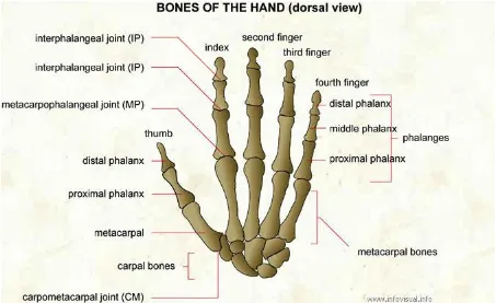
[image:16.595.112.565.292.569.2]Figure 3 Bones of the hand (Infovisual 2013)
Table 1 Muscle insertion and action (Martini 2002)
Muscle Insertion Action Flexor carpi radialis Bases of second and third metacarpal
bones
Flexion and abduction at wrist Flexor carpi ulnaris Pisform bone, hamate bone, and base of
fifth metacarpal bone
Flexion and adduction at wrist Palmaris longus Palma aponeurosis and flexor
retinaculum
Extensor carpi radialis longus Base of second metacarpal bone Extension and abduction at wrist Extensor carpi radialis brevis Base of third metacarpal bone Extension and abduction at wrist Extensor carpi ulnaris Base of fifth metacarpal bone Extension and adduction at wrist Abductor pollicis longus Lateral margin of first metacarpal bone Abduction at joints of thumb and wrist Extensor digitorum Posterior surfaces of the phalanges,
fingers 2-5
Extensions at finger joints and wrist Extensor pollicis brevis Base of proximal phalanx of thumb Extensions at joints of thumb; abduction
at wrist
Extensor pollicis longus Base of distal phalanx of thumb Extensions at joints of thumb; abduction at wrist
Extensor indicis Posterior surface of phalanges of index finger(2), with tendon of extensor digitorium
Extension and adduction at joints of index finger
Extensor digiti minimi Posterior surface of proximal phalanx of little finger(5)
Extension at joints of little finger Flexor digitorum superficialis Midlateral surfaces of middle phalanges
of fingers 2-5
Flexion at proximal interphalangeal metacarpophalangeal and wrist joints Flexor digitorium profundus Bases of distal phalanges of fingers 2-5 Flexion at distal interphalangeal joints
and, to a lesser degree, proximal interphalangeal joints and wrist Flexor pollicic longus Base of distal phalanx of thumb Flexion at joints of the thumb Adductor pollicis Proximal phalanx of thumb Adduction of thumb Opponens pollicis First metacarpal bone Opposition of thumb
Palmaris brevis Skin of medical border of hand Moves skin on medical border toward midline of palm
Abductor digiti minimi Proximal phalanx of little finger Abduction of little finger and flextion at its metacarpo-phalangeal joint Abductor pollicis brevis Radial side of base of proximal phalanx of
thumb
Abduction of thumb Flexor pollicic brevis Radial and ulnar sides of proximal
phalanx of thumb
Flexion and adduction of thumb Flexor digiti minimi brevis Proximal phalanx of little finger Flexion at joints of little finger Opponens digiti minimi Fifth metacarpal bone Opposition of fifth metacarpal bone Lumbrical(4) Tendons of extensor digitorum to digits
2-5
Flexion at metacarpophalangeal joints 2-5; extension at proximal and distal interphalangeal joints, digits 2-5 Dorsal interosseus(4) Bases of proximal phalanges of fingers
2-4
Abduction at metacarpophalangeal joints of fingers 2 and 4; flexion at
metacarpophalangeal joints; extension at interphalangeal joints
Palmar interosseus* Bases of proximal phalanges of fingers 2,4 and 5
Adduction at metacarpophalangeal joints of fingers 2,4 and 5; flexion at
metacarpophalangeal joints; extension at interphalangeal joints
3.2
Research the background on EMS and the control of muscles,
voltage levels, optimum electrode area and shape, optimum
electrode material and position placement on the forearm.
The optimum electrode shape is small enough to localise the muscle needing to be stimulated, while being large enough to not cause pain when energised (Tamaki et al. 2011). For the stimulation of the forearm of an average-sized male, a 1x1cm gel pad is sufficiently large enough to avoid causing pain while being small enough that accidental simulation of adjacent muscles is unlikely. The size that is being investigated for this project is 1x4cm strip, which may be reduced or enlarged following commencement of the trials. The electrode material chosen is self-adhesive gel electrodes, the same as that used in PossesedHand. These were selected as they cause the least amount of discomfort to the user and adhere to the skin whereby limiting movement. The electrodes will be attached to a Velcro armband enabling them to be arranged to suit the individual physique of each subject.
Position and placement of the pads will be carried out by tensing the muscle needing stimulation and attempting to place the pad directly over it. The pad will then be adjusted to allow for maximum effect on the target muscle and minimal effect on the surrounding muscles.
3.3
Critically examine techniques and choose a method which best
meets requirements.
The techniques that are to be used for EMS and for the hardware are primarily based on those modified by the authors of PossesedHand, as they are more readily adaptable to the needs of this project than other control techniques viewed.
The muscles that are viewed as being accessible for this project include:- o Superficial flexor
o Long flexor of the thumb o Common digital extensor o Flexor carpi radialis o Long palmar o Flexor carpi ulnaris
These muscles were selected as they are most easily accessible and should provide a varied range of movement.
Basic weight and resistance measurement techniques will be utilised for taking muscle strength measurements as they require minimal equipment.
It will be necessary to develop and implement measurement techniques to compare the effect of EMS on a subject with a control to test for the increase of muscle strength, dexterity and endurance. Weight lift or compression force will be utilised in undertaking the strength test.
3.4
Design and build a prototype.
This stage of the project will require the use of the USQ provided PLC, a Siemens PLC- Simatic S7-200 CPU with expansion EM-222 Ports with a TD400C GUI (Screen). This unit is fast enough to provide the required PWM outputs and with the additional expansion modules, will provide enough outputs for this application. An isolation circuit will be adapted for the low side switching.
The power supply is going to be a low energy source or have protection to limit any faults that may occur. Only a single rail power supply is required as each muscle can be stimulated individually for <1ms before the next targeted muscle is stimulated because of the extremely low duty cycle being implemented.
o Perform hand movements in a controlled manner, with the aim of having opposing muscles resisting to provide a tailored ‘exercise’
o Perform a simple task with hand movement
o Assess ability to control individual finger movement
o Investigate repetitive synchronized sound and muscle stimulus for possible re-teaching of the brain applications
o Investigate application of targeted EMS with other muscle groups
4
Literature review
4.1
‘Functional electrical stimulation cycling improves body
composition, metabolic and neural factors in persons with
spinal cord injury’
The purpose of this medical trial was to investigate the effects of Functional Electrical Stimulation (FES) on neurological factors, body composition and metabolic functions. These were trialled on eighteen individuals with spinal cord injuries ranging from C4 (Neck, controlling diaphragm) through to T7 (middle back, controlling abdominal muscles), most with no lower motor score. The FES part of the trial consisted of the participants cycling at a cadence of 49rpm with assistance from the FES device (Ergys2, Therapeutic Alliances, Fairborn, OH, USA) and a therapist, if required, for 30 minute sessions 2-3 times per week for a 10 week period with increasing resistance.
Some of the results and information from this trial which are applicable to this project are:- Stimulation frequency of a constant 50Hz
Stimulation level was set not to exceed 140mA
1 minute warm up required to allow for normalisation of tone and passing of reactive spasms that may occur upon initiation of motion
Work done by participants output at less than 1 kJ 1st week and over 5kJ by the 10th week
Muscle mass had increased by about 5%
Stimulation intensity had to be increased as the muscles fatigued in each session Stimulation intensity requirements decreased over the 10-week period even
4.2
‘Pulse charge and not waveform affects M-wave properties
during progressive motor unit activation’
This study investigates the change in recorded M-waves with progressive motor unit (MU) activation by way of transcutaneous electrical stimulation with differing shaped pulsed waveforms. The 3 waveforms tested were sinusoidal, square and triangular with differing stimulation levels. It was found that the MU activation was a function of the applied charge and not of the waveform it was applied with. It was found that the test subjects were more comfortable when MU activation was performed with the triangular waveform when compared to the others.
Some points presented in this paper that are relevant to this project are:- It is the charge not the waveform that that has motor unit activation Triangular waveform causes the least discomfort to the test subject
Pulse duration has a disproportionate positive effect on torque and activated muscle cross-sectional area than increasing current amplitude and stimulation frequency (Gorgey et al 2006)
4.3
‘The functional value of electrical muscle stimulation for the
rehabilitation of the hand in stroke patients’
The extensor and flexor carpi radialis muscles of 12 patients were electrically stimulated and compared with the results of standardised active repetitive training of the fingers and hand. The conclusion of the study was that ‘repetitive electrical muscle stimulation does not improve biomechanical or functional motor parameters of the centrally paretic hand and arm. The repetitive motor training, however, is appropriate to improve biomechanical and functional movement parameters significantly.’ It comes to the conclusion that active motor training, with sensori-motor coupling to affect the motor centres of the brain, is more beneficial than EMS.
Some points presented in this paper that are relevant to this project are:-
The electrical stimulation sessions were conducted for 20 minutes twice daily Self-adhesive, flexible electrodes 2.5x3cm
75-80Hz, 0.5ms pulse with a current intensity of 10 to 80mA Current adjusted to produce maximum wrist extension and flexion
Grip strength was trained by way of 2 metal bars separated by a variable number of springs
Wrist extensions were performed using low resistance weights, initially 0-600 grams, then up to 2kg
Grip strength was measured by way of a digital pinch/grip analyser (Kuck Medizin-Elektronic Corp.)
4.4
‘PossessedHand: Techniques for controlling human hands using
electrical muscles stimuli’
generation of such devices. Other devices used for electro-muscle stimulation replicated a glove, covering the hand. The majority of users surveyed, reported that they found the glove uncomfortable as it inhibited tactile feedback. Therefore, the authors, seeking to create a device that would be non-intrusive for the user, developed a device that attaches to the forearm, away from the hand. The device uses electrode pads on the skin surface fastened to the forearm to stimulate the muscles controlling the hand. It is noted that when this article was written (2011) there had been no research into controlling the position of the hand solely through electrical stimulation to the forearm. The techniques used are similar to Functional Electrical Stimulation (FES) and Electrical Muscle Stimulation (EMS). 14 channels were used at 3 levels of electrical stimulation to stimulate 7 muscles, with the pads on the upper forearm and lower forearm being simultaneously selected to stimulate the muscle. Muscles are selected by stimulation levels, though the muscle at the shallower depth is always stimulated.
Some points presented in this paper that are relevant to this project are:- The 3 pre-set voltages are: 17, 23 and 29V
PossessedHand stimulated 7 muscles:- o Superficial flexor
o Deep flexor
o Long flexor of the thumb o Common digital extensor o Flexor carpi radialis o Long palmar o Flexor carpi ulnaris Different pads were investigated
o Dry electric type: made of metallic sheets and are used to measure Galvanic Skin Response (GSR). Cause pain when contact area is small. o Liquid gel electric pads: made with porous foam that absorbs liquid gel to
enable good contact. Causes pain when gel is depleted due to reduced contact area.
o Solid gel type pads: These include conductive gel on a pad that is reusable and leaves no residue. Contact area is assured with high reliability.
4.5
‘Electrical stimulation for neuromuscular testing and training:
state-of-the art and unresolved issues’
This article explores the different uses of and the techniques and devices used in the electrical stimulation of muscles, while looking at the perception of what they can achieve. It primarily focuses on Neuromuscular Electrical Stimulation (NMES) which is generally used with the muscles in static conditions without any functional occurring movement. It explores the potential of this method to be a strength training tool, rehabilitation tool, testing tool and a post-exercise recovery tool.
4.6
Well-life literature article number IM-SA-029 RevA12
The following points are taken from literature produced by Well-Life Healthcare, and relate to the application and use of re-usable self-adhesive electrodes (Well-Life 2013):-
The electrodes should not be kept on the body longer than 1 hour per treatment time
The electrodes should not be shared due to the risk of adverse skin reactions and transmission of diseases
The long-term effects of cutaneous electrodes for electrical stimulation and/or recording are unknown
Stimulation electrodes should never be placed over open wounds or rashes, or over swollen, red, infected or inflamed areas or skin eruptions (e.g. phlebitis,
thrombophlebitis, varicose veins)
Do not place stimulation electrodes over, or in proximity to, cancerous lesions Electrodes should be applied only to normal, intact, clean, healthy skin
The size, shape, and type of electrodes may affect the safety and effectiveness of electrical stimulation
Users may experience skin irritation and burns to the skin beneath the electrodes Skin should be cleaned thoroughly prior to the application of electrodes to ensure
5
Safety
5.1
Construction
[image:29.595.107.531.497.770.2]This research project utilises a significant amount of electrical hardware and software, some of which has needed to be manufactured while others were purchased ready-made and then adapted. The equipment to be manufactured includes: a low level switching board; a dual DC/DC step-up circuit with voltage control and regulation; high speed, high level active switch; cables; armband; and electrode adaptation. The activities that require risk assessment include cutting, trimming, sewing, gluing, soldering and live testing. Risk assessments were performed for each task in order to mitigate any risks. For each task at least 2 forms of control were implemented to reduce the risk and consequence of harm. PPE was the last line of protection in cases where other forms of control were insufficient. An example risk assessment for the production of a PCB is included in Table 2. The safety controls include safety glasses, long sleeved shirt, technique, ventilation and correct tools, such as a brass sponge to remove solder from the tip of soldering iron, in place of flicking molten solder off.
Table 2 Risk assessment for populating and soldering a PCB
Damage Safe guards Consequence Probability Risk rating
Lead burns Lead in the eye
Technique-No flicking of solder PPE eyewear PPE long-sleeved shirt
Requires 1st aid Unlikely Minor to Moderate Leads of components in eye Technique-Cut away from person Lead-retaining cutters PPE eyewear
Requires 1st aid Unlikely Low risk
Toxic inhalation of fumes Ventilated Room Fume extractor/ Long-term respiratory problems
filter
Table 3 Probability vs consequence
5.2
Design
Step-up converters were used from a regulated 12V supply so that if a fault should occur within the devices, the potential across the pads would be limited to 12V, which would have a negligible effect on the user. 20-24V is supplied to the linear 12V regulator. If a catastrophic fault should occur within the 12V regulator, such as the input shorting to the output, then the design of the circuit has a 13V Zenner which clamps the voltage and causes an overload to take place within the PSU. The user is alerted to fault and is then able to take action. Provision has been made for the output voltage from the DC-DC convertors to be monitored by the PLC, thereby operating in a closed loop for the output voltage to be controlled. The electrode pads are limited to 0.1W/cm^2, which is the maximum recommended by the manufacturer (Well-Life 2013). Due to the design properties of the PLC, the voltage is clamped above 28.8V. Output wires are colour coded to assist in connecting the electrodes to the correct channels.
5.3
Setup and Operation
The Velcro armbands can be attached in such a manner that there is compliance to account for muscle contraction/expansion without restricting the blood supply.
6
Methodology
6.1
Question
Can an EMS device target particular muscles so as to rebuild specific wasted muscle, can two opposing muscles provide enough resistance for muscle regeneration to occur.
6.2
Hypothesis
It is theorised that simultaneously stimulating two opposing muscles, whereby creating a variable opposing force, will aid in the rehabilitation of wasted muscle. This method removes the need for a manual form of resistance such as weights or springs. The use of low levels of targeted EMS over an extended period of time can aid in the recovery of wasted muscle. Using the same method, a healthy muscle can increase in strength, thereby confirming the hypothesis.
6.3
Test
Muscles are stimulated with a PLC based control system daily, for a set period of time, with the stimulated muscles then being tested against a control for any improvement in strength. For this project it will be the author’s left arm under test with the right arm being the control.
7
Experimental System
7.1
System Design
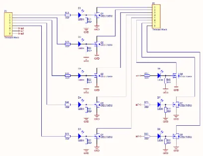
[image:33.595.162.510.300.564.2]The system was designed around the hardware available at USQ. This consisted of a bench top variable PSU and a Siemens S7-200 PLC, expansion modules and TD400 Screen. In addition to this, a low level switching and a variable step-up circuit were also required. A block diagram of these is shown in Figure 5.
Figure 5 System block diagram
7.2
Step-up DC/DC convertor
The step-up switching ICs chosen for this application were the LM2577T. These combine all the functions required for variably stepping up the voltage except an op-amp, which is easily added. The voltage required on the feedback pin is 1.23V. In order to facilitate a stable reference voltage, a resistor divider is devised which is fed into a buffering op-amp (U2C, Figure 6). The calculations for the resistors are shown in Equation 1.
PLC Relay Relay Step-up Switching board
User control screen
Electrode/
Arm interface
Figure 6 Step-up and high level switching board
Equation 1 Voltage reference calculation
This calculated value is within 0.05V of the desired value and is therefore acceptable. The op-amp chosen for this application is the LMC6484IM. Some of its features include: rail to rail operation; relatively high slew rate; relatively high current sourcing; and, sinking and high input impedance being a CMOS device. The gain required for this application is 1, so all resistor values can be identical. value is chosen arbitrarily as . This calculation is
shown in Equation 2. Equation 2 Op-amp gain of 1
The PLC is capable of outputting 0-10V on its analogue outputs, which are then required to control the output up to 28.8V. For the sake of simplicity, 30V is used in the calculations and to account for any errors in the circuit. and shown in Figure 6, are variable
resistors included on the step-up regulator circuits which are designed to provide a means of adjusting the set output voltage of the regulator circuits. The track is cut between
and therefore they can be incorporated into the design to provide an adjustable
voltage from the PLC. The resistor then needs to be adjusted so that a 1:1 ratio can be made from the output of the PLC to the regulators’ usual feedback, which means a 1:3 ratio is required from the variable resistor to provide a full scale of 30V on the output. This calculation is shown in Equation 3.
Equation 3 Values of and
( ) ( )
The value of is required to be set on and . Provision is also made for the
PLC not controlling the output voltages and so and are also included so the output
can be set again by and . These were also used as test points for diagnostics of the
circuit.
7.3
High Level switching
TIP31C NPN transistors were chosen for the switching of the high level output as they are able to withstand 100V and capable of carrying 3A and a of about 90. The
requirements for stimulation are tentatively set at 30V and no more than 200mA. The collector resistor can be calculated as per Equation 4.
Equation 4 Values of and for base current limit
( ) ( ) ( )
sufficient to reach full voltage at the emitter within the switched period (between 0.1-1ms). The datasheet specifies that the transistor is able to handle up to 1A current through its base (Motorola, 1995). With this in mind, a 300Ω resistor is chosen and checked if it conforms to these specifications (Equation 5) and its theoretical output current (
Equation 6).
Equation 5 current limit
( )
Equation 6 Values of and for base current limit
So it can be seen that the transistor is driven into saturation and it also improved the peak voltage and transient time. These equations show that the transistor is driven into saturation and that the peak voltage and transient time have been improved.
[image:36.595.113.312.516.662.2]The turn off transient time was not acceptable; therefore 3.9KΩ resistors were placed in parallel with the base/emitter on the inputs to help drive the transistors off faster.
7.4
Zero reference multiplexer
[image:37.595.114.522.221.536.2]The low level switching is achieved by having 8 N-channel MOSFETs (STD17NF03) switching to ground. These are being controlled by the outputs from the PLC going through a voltage divider that also has the property of driving the MOSFETs off.
Figure 8 Low level switching board
The MOSFETs are suitable for this application as they are rated for 30V, specified for high speed DC/DC convertors and have a low internal resistance. The resistors are being used as a voltage divider for the gate, in order to limit the gate voltage to 12v. The resistors also serve to limit the current through the LEDs and to bias the MOSFETS off when they are not selected for use. The LEDs purpose is for a visual indication of operation only.
The resistors values can be calculated as shown in Equation 7. Equation 7 Values of to for LED current limit
( ) ( )
7.5
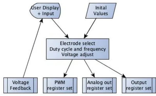
PLC Programming
[image:38.595.118.422.526.714.2]The PLC is programmed to apply a voltage to two muscle groups with a defined duty cycle, frequency, and voltage; while also offering a single channel for voltage feedback. The PLC offers a 16 bit resolution on the PWM duty and cycle times, coupled with the need of µs time range for the duty cycle, this equates to 65.536ms cycle time. This means that with a duty cycle time of 200µs a frequency range of 15Hz to 5kHz can be achieved, although in reality an upper limit of 100Hz is required.
Figure 10 PLC user screen Pad select
[image:39.595.113.341.328.461.2]The user is able to select which channels to enable for pad selection in order to choose which muscles are stimulated.
Figure 11 PLC user screen Voltage Adjust
The voltage for each channel can be adjusted to the required level on the voltage adjust screen. In this instance the maximum voltage that can be set is 30V.
Figure 12 PLC user screen Duty Cycle and Frequency
[image:39.595.113.340.540.672.2] On time range : 50-800 µs
Cycle time range: 65536-10000 µs (15-100Hz)
These times are to simulate the output from the nervous system.
7.6
Muscle Interface
The electrode/arm interface has been chosen based on previous work done by PossesedHand (2011) which was TYCO gel electrode pads attached to a Velcro backing to keep the pads in place. The pads were adapted from TENS devices utilising either a 40x40 or 50x50mm pad which was then cut down to a strip of 12mm wide. Using the smaller strips enables improved selectivity of the muscle while minimising overlap with adjacent muscles.
7.7
Strength Measurement
[image:40.595.117.499.470.739.2]The selected method of strength testing is to measure the pincer strength of specific fingers. The test setup consisted of a set of scales (Satrue SK-200H) with an aluminium beam acting as a lever upon it. The reason for the use of the aluminium beam is to reduce the force on the scales as they are only rated to 2kg and the expected force is up to 20kg.
Figure 13 Strength testing setup (pistopin, 2013)
Force- thumb
Opposing force- finger L
L 10
The beam is placed on the edge of a desk with one end on the scales and the other on a spacer to increase its height marginally. The placement of the test force is calculated from the ratio of force reduction and the length of the beam as shown in Equation 8.
Equation 8 Position of applied force on beam
This distance is scribed onto the beam for repeatability and consistency of measurements. The setup is shown in Figure 13. The measurements displayed on the scales need to be scaled by a factor of 10 to account for the loss in force due to the lever. The measurement setup is then tested with a calibrated 50gm weight to check its accuracy, which it passes initially and is pre-tested before every measurement session. The scales used can display increments of 1gm; therefore, with scaling that equates to 10gm, the highest resolution available will be in increments of 10gm.
8
Results
8.1
Collection
[image:42.595.113.540.307.722.2]The PLC based experimental system was tested to see if it could stimulate opposing muscles. The flexor digitorum superficialis muscle was chosen as it is large muscle close to the surface and inserts in to the middle phalanges of all the fingers for a flexion action. It is covered by the thin Palmaris longus muscle at its origin and is adjacent to the flexor carpi radialis muscle, but is relatively exposed.
In anticipation of the application of the electrodes, the arm being stimulated is first washed with soap and warm water to remove any oils and dirt that could interfere with the adhesion and electrical contact of the pads (Welllife 2013). To find the location of the muscles for pad positioning, the muscles are first identified from anatomy diagrams (Netter 1989) as is their function (Hutchinson et al. 2007). The gel pads are then applied in the general area with the negative electrode on the upper forearm and the positive electrode on the lower forearm thereby being placed directly above the muscle of interest. A low intensity pulse is then provided to the electrodes to confirm the correct muscle has been located and selected. Next, the pads are manipulated while attached by stretching the skin to move and rotate for the best selectivity and maximum muscle contraction. The pads are then relocated to this position by peeling them and re-applying them.
The PWM was set to 200µs/20000µs (50Hz), voltage was ramped up to the maximum 30V and the result with the modified pads was only feint twitching of the fingers/muscle. The modified small pads were replaced with the full sized un-modified version and the muscle contracted partially, as well as unascertainable surrounding muscles. Further testing showed that a substantially higher voltage was required to overcome the layer of sub-cutaneous fat for the stimulation of the underlying muscles with the application of the modified electrodes. While the larger electrodes did stimulate muscles, they did not have the selectivity of the modified slim electrodes that was required. As all the switching components of the system were limited to 30V or below, it was not possible to continue testing with the setup as modifications to the base hardware was not possible. However, it was shown that switching between muscles is possible with this setup, but there was not a high enough electrical potential to conduct the targeted EMS testing.
When the flexor digitorum superficialis muscle is stimulated, the third and fourth digits have about of flexion movement with the second digit having almost an imperceptible movement and the fifth digit about of movement. With this in mind, when the extensor digitorium muscle is stimulated, all fingers extend with the wrist trying to extend also with a small amount of adduction. Therefore, it could logically be concluded that the fingers with the most resistive force would be digits three and four, and so the most strength gain would be found in these two digits from the increase of strength through stimulation.
The required stimulation levels of the flexor digitorum superficialis muscle and extensor digitorium muscle to be comfortable are shown in Figure 15 and Figure 16 to be about 54V and 67V respectively. The PWM on time is 200µs at a frequency of 55Hz. This equates to a peak current stimulation level of 20mA and 30mA respectively.
[image:44.595.119.518.368.504.2]Figure 15 Stimulation of Flexor digitorum superficialis muscle
Figure 16 Stimulation of Extensor digitorium muscle
Equation 9 Peak power applied to cutaneous tissue above the Flexor digitorum superficialis muscle
⁄
⁄
Equation 10 Peak power applied to cutaneous tissue above the Extensor digitorium muscle
⁄
The peak stimulation levels for the cutaneous surface area is higher than what is recommended by Well-life(2013) for about 50µs of the 200µs on time, and averages out to be less than the defined over the entire 200µs on time. With this in mind, testing times will be limited to 10 minute sessions per day to mitigate any unforeseen problems.
[image:45.595.117.525.316.626.2]Stimulation is performed with the arm resting in a position as to not constrict the finger movement, such as shown in Figure 17, but not limited to this. No activity is undertaken with the left arm during the stimulation sessions so as to not influence the final results.
Figure 17 EMS with mobilitymate of the Flexor digitorum superficialis and Extensor digitorium muscles
The re-use of the stimulation pads was initially expected to be about 30 times as per the included literature, however it was found that after about 10 uses the gel on the pads began to deteriorate and contact was not uniform, requiring a higher stimulation level and causing an uncomfortable sensation on the skin when stimulation took place. Subsequently, the pads were replaced when this occurred.
8.2
Discussion
As can be seen in Figure 18, all the datasets have a positive trend over the test period with an amount of deviation to the trend line. The differences are then calculated (Table 4). Table 4 Gradients compared
Right Left Difference
Improvement of Left over Right (kg)
All 0.056552 0.063537 0.006986 0.209566
2nd 0.063003 0.064561 0.001557 0.046719
3rd 0.063315 0.071079 0.007764 0.232925
4th 0.050211 0.069143 0.018932 0.567964
5th 0.05059 0.058509 0.00792 0.237597
While it is apparent that the strength of both hands has increased over the testing period, the hand under test (left hand) has improved more than the control (right hand). This comparison was done by subtracting the gradient of the control from the gradient of the test.
9
Future Research Recommendations
There are many improvements and changes that could be made to this project which could make it more efficient or change the outcomes. Here are a few recommendations for future research expansion on this topic:-
[image:50.595.112.427.280.460.2]9.1
Core saturation output limiting
Figure 19 Partial output driver circuit
The underlying idea is that the output is limited to the maximum flux capacity of the core. If there is a fault on the driver side of the circuit then the output can only be driven as much as the transformer’s core allows until it saturates.
The voltage on the output is controlled by a manual or digital potentiometer. This controls the stimulation level on the muscles by shunting excess current through the potentiometer thereby simplifying the driver section of the step-up circuitry.
This idea is derived from a commercially available TENS product (Mobilitymate 37624) as how to limit any fault conditions.
For the data collection of this project, the bar was squeezed and the peak value was observed and recorded. This has inherent flaws such as the observer was unable to confirm the reading which was visible for half a second, the scales only have a refresh rate of 2Hz, so a peak value is possibly not measured and endurance is unable to be assessed easily by measuring the load values at subsequent time intervals.
I would suggest that the scales be replaced with a load cell and a computer to data log the results. This would give a true maximum load value and endurance would be easily calculated.
9.3
Stimulation pad matrix
The pads used for stimulation were adapted from larger sized pads by cutting them into narrow strip so they could target individual muscles. These then had Velcro attached to the back of them so they could be fixed in place on the armband to make future location of the pads on the arm easier. This was not always the case as any deviation from its previous location would inhibit correct stimulation. The pad sizes were also fixed and no attempt was made to find the optimum pad size and shape for a particular muscle.
I would recommend that a grid array is made for stimulation that can have multiple points operational so the size, shape and area can be configured. The investigation should also focus on the minimum resolution required to enable successful muscle selection and stimulation.
9.4
Multiple muscle activations with single channel
This project was limited to stimulating two opposing muscles only simultaneously with 2 separate channels. It was found that if the pads in a matrix can be operated fast enough only a single channel is required to achieve the same result.
10
Project Conclusion
All the research and project objectives have been addressed and some positive results have been observed. A brief discussion of the objectives follow:-
1. Research the background information on muscles required for hand control, anatomy, EMS and the control of muscles, voltage levels, optimum electrode area and shape, optimum electrode material and position placement on the forearm. Literature reviews were undertaken on several papers relevant to the aim of this project. Background study on anatomy of the arm and hand was also completed. The technical paper by Tamaki, Miyaki & Rekimoto 2011 provided direction on the suitable sizing of the electrodes to be placed on the arm as well as on the differing stimulation levels. Instruction on the correct placement of the electrodes was obtained from a number of medical reference books (Hutchinson et al 2007)(Netter 1989).
2. Critically examine techniques and choose a method which best meets requirements.
The method chosen for this project was based on Possessedhand (2011) which utilised a HCI. The Possessedhand (2011) user wore arm-bands on their forearm (minimising discomfort by avoiding the hand) which were connected to and controlled by the computer interface. Adaptations made from the Possessedhand (2011) technique included: some of the controlling mechanisms from the computer interface; the electro interface setup; the use of arm bands; electrode sizing and voltage stimulation levels. The Possesshand (2011) method was initially adapted to be used with a PLC before being further adapted to target a single pair of muscles using a TENS unit.
3. Design and build a prototype.
device was not used for the final stimulation, the process by which it would function and stimulate muscles, were it not for the voltage limitations, has been outlined.
4. Develop and implement measurement techniques to compare the effect of EMS on a subject with a control to test for the increase of muscle strength, dexterity and endurance. Test it from baseline data-
References
A. Botter, R. Merletti, M.A. Minetto, Pulse charge and not waveform affects M-wave properties during progressive motor unit activation, Journal of Electromyography and Kinesiology, Volume 19, Issue 4, August 2009, Pages 564-573, ISSN 1050-6411, 10.1016/j.jelekin.2008.03.009.
EKU Eastern Kentucky University, 2013, BIO 301-Human Physiology-Muscle, http://people.eku.edu/ritchisong/301notes3.htm, Accessed 29/5/2012
Emi Tamaki, Takashi Miyaki, and Jun Rekimoto. 2011. PossessedHand: techniques for controlling human hands using electrical muscles stimuli. In Proceedings of the SIGCHI Conference on Human Factors in Computing Systems (CHI '11). ACM, New York, NY, USA, 543-552. DOI=10.1145/1978942.1979018 http://doi.acm.org/10.1145/1978942.1979018 European Journal of Applied Physiology, October 2011, Volume 111, Issue 10, pp 2391-2397
Griffin, L., Decker, M., Hwang, J., Wang, B., Kitchen, K., Ding, Z., and Ivy, J. Functional electrical stimulation cycling improves body composition, metabolic and neural factors in persons with spinal cord injury. Journal of Electromyography and Kinesiology 19(4) (2009), 614―622.
Horst, H., Maier-Loth ML, and C, E. The functional value of electrical muscle stimulation for the rehabilitation of the hand in stroke patients. Scandinavian journal of rehabilitation medicine 29(1) (1997), 3.
Hutchinson, Matt, Mallatt, Jon, Marieb, Elaine N., Wilhelm, Patricia Brady, Hutchings, Ralph T., Zanetti, Nina, 2007, A Breif Atlas of the Human Body, Pearson, Benjamin Cummings, San Francisco, CA
Infovisual, 2013, Bones of the hand dorsal view,
http://www.infovisual.info/03/img_en/027%20Bones%20of%20the%20hand%20%28dorsal %20view%29.jpg, Accessed 29/5/12
Kandel, Eric R., Schwartz, James H., Jessell, Thomas M., c1991,Principles of neural science,
New York, Elsevier, pp 19-35
Lieber, Richard, 2002, Skeletal Muscle Structure, Function, and Plasticity: The Physiological Basis of Rehabilitation, Lippincott Williams and Wilkins, ISBN-13: 978-0781730617
Martini, Frederic., 2005, Fundamentals of anatomy & physiology, 7th edition, Prentice Hall, New Jersey, pp 355-362
McCracken, Thomas, New Atlas of Human Anatomy, 1999, China: Metro Books. pp. 1–120. ISBN 1-5866-3097-0.
Motorola, 1995, ‘Motorola Bipolar Power Transistor Device Data’ for ‘TIP31A TIP31B TIP31C TIP32A TIP32B TIP32C’ Document ID TIP31A/D, USA / EUROPE: Motorola Literature
Distribution;P.O. Box 20912; Phoenix, Arizona 85036. 1–800–441–2447
Netter, Frank H., c1989, Atlas of human anatomy, CIBA-GEIGY Corp, Summit NJ, plates 414-440
Nicola A. Maffiuletti, Marco A. Minetto, Dario Farina, Roberto Bottinelli,Electrical
stimulation for neuromuscular testing and training: state-of-the art and unresolved issues, Roman Tsivkin reviewed by ,Muscle Atrophy Exercises,
http://www.livestrong.com/article/354228-muscle-atrophy-exercises/ , Accessed 28 February 2013 9:17 AM
Bibliography
Aids to the investigation of peripheral nerve injuries, War Memorandum No. 7 (revised second edition, 1943), London – Her Majesty’s Stationery Office, 616.833-00-4-04 Anatomical terms of motion, en.wikipedia.org/wiki/Anatomical_terms_of_motion, Accessed 20-10-2013 11:17
EKU Eastern Kentucky University, 2013, http://people.eku.edu/ritchisong/301notes2.htm hand_9_lg.gif, http://etc.usf.edu/clipart/4400/4465/hand_9_lg.gif ,
http://www.picstopin.com/640/hand-clipart-etc/http:||etc*usf*edu|clipart|4000|4015|hand_6_md*gif/, Accessed 16:32 15/10/2013 HISTOLOGY BIOL-4000 LECTURE NOTES#6-MUSCLE,
http://www.auburn.edu/academic/classes/zy/hist0509/html/Lec06notes-muscle.html, accessed 25/09/2013 22:25
McMinn, R. M. H. , Hutchings, R. T., c1988 , A color atlas of human anatomy, Year Book Medical Publishers, Chicago
Muscles, http://users.rcn.com/jkimball.ma.ultranet/BiologyPages/M/Muscles.html O'Rahilly, Müller, Carpenter & Swenson, Basic Human Anatomy,
http://www.dartmouth.edu/~humananatomy/part_2/chapter_11.html, Accessed 22/2/2013 11:06
Oxford dictionary online, http://www.oxforddictianaries.com/
Therapeutic Goods Administration, http://www.tga.gov.au/industry/devices.htm The Mysteries of Myelin Unwrapped ,
http://www.sciencemag.org/content/304/5671/688.full
Appendices
ENG 4111/2 Research Project
Project Specification
For: David Dobson
Topic: Electro Muscle Stimulus System for Wasted Muscle Rehabilitation
Supervisor: Dr Les Bowtell
Sponsorship: Faculty of Engineering & Surveying
Project Aim: Muscle degeneration is where a muscle deteriorates and is unable to perform at its prior functionality. Muscle degeneration can be a symptom of aging, injury, nerve damage, stroke, motor neuropathy, muscular dystrophy, and arthritis as well as others.
The project aim is to design an apparatus to aid in the rehabilitation of forearm muscles related to finger and hand movement by way of increasing muscle strength and flexibility in the muscles and related ligaments. The user is to wear the apparatus for periods of time from a number of minutes to hours. It has the ability to promote muscle regeneration and to stop degeneration, by way of electro stimulation of the muscles, during periods of inactivity.
Program:
1. Research the background information on muscles required for hand control, anatomy, EMS and the control of muscles, voltage levels, optimum electrode area and shape, optimum electrode material and position placement on the forearm. 2. Critically examine techniques and choose a method which best meets requirements. 3. Design and build a prototype.
4. Develop and implement measurement techniques to compare the effect of EMS on a subject with a control to test for the increase of muscle strength, dexterity and endurance. Test it from baseline
data-a. Strength test: Typically by way of weight lift or compression force
b. Endurance test: Typically by way of repetitive action against known force.
As time and resources permit:
1. Perform hand movements in a controlled manner, with the aim of having opposing muscles resisting to provide a tailored ‘exercise’
2. Perform a simple task with hand movement
3. Assess ability to control individual finger movement
4. Investigate repetitive synchronized sound and muscle stimulus for possible re-teaching of the brain applications.
5. Investigate application of EMS with other muscle groups
Agreed:
Student Name: David Dobson
Supervisor Name: Your Supervisor (add another row if more than one)
Date: The date
Appendix B Program listing for data interpretation
Code 1 Plotting of data
%% David Dobson final year project 2013 results
clc;clear all;close all;
y=[15.5000000000000,14.4000000000000,10.7000000000000,9.30000000000000,8.500000000000 00,8.30000000000000,7.30000000000000,8.10000000000000,5.80000000000000,5.600000000000 00;17.2000000000000,16.3000000000000,13.6000000000000,10.3000000000000,10.80000000000 00,8.60000000000000,8,7.90000000000000,7.30000000000000,6.90000000000000;17,15.200000 0000000,12.5000000000000,11,12.6000000000000,11.3000000000000,9.70000000000000,8.8000 0000000000,6.10000000000000,7.20000000000000;16.6000000000000,14.1000000000000,11.200 0000000000,9.20000000000000,11.6000000000000,9.80000000000000,9.50000000000000,9.3000 0000000000,6.40000000000000,5.80000000000000;16.1000000000000,16.1000000000000,12.100 0000000000,10.8000000000000,11.5000000000000,10,9.20000000000000,9.20000000000000,6.2 0000000000000,6.30000000000000;16.5000000000000,14.5000000000000,12.3000000000000,11. 5000000000000,11.3000000000000,10,9,9,6.40000000000000,7.30000000000000;16.6000000000 000,15.6000000000000,12.1000000000000,10.3000000000000,11,9.60000000000000,8.60000000 000000,9,6.20000000000000,6.80000000000000;17,15.8000000000000,12.9000000000000,11.40 00000000000,11,9.60000000000000,9.70000000000000,9.70000000000000,6.60000000000000,6. 60000000000000;16.6000000000000,15,12.7000000000000,11,12.3000000000000,9.90000000000 000,9.20000000000000,9.30000000000000,7,7.80000000000000;17,16.4000000000000,13,11.40 00000000000,11,10.7000000000000,9,9.80000000000000,6.40000000000000,8.10000000000000; 17.2000000000000,15.8000000000000,12.6000000000000,10.9000000000000,11.5000000000000, 10.2000000000000,9.50000000000000,8.90000000000000,6.80000000000000,7.20000000000000; 17,15.6000000000000,13,11.3000000000000,11.4000000000000,9.80000000000000,9.900000000 00000,9.30000000000000,6.80000000000000,7.80000000000000;17.5000000000000,15.40000000 00000,13.5000000000000,10.3000000000000,11.8000000000000,10.7000000000000,9.400000000 00000,8.80000000000000,6.80000000000000,6.90000000000000;17.3000000000000,15.90000000 00000,12.8000000000000,11.4000000000000,11.3000000000000,10,9.40000000000000,9,6.6000 0000000000,7.10000000000000;16.8000000000000,15.6000000000000,12.7000000000000,11.600 0000000000,12.1000000000000,10.5000000000000,9.70000000000000,9.20000000000000,6.7000 0000000000,7;17.6000000000000,16.4000000000000,13.3000000000000,11,12.1000000000000,1 0.5000000000000,9.20000000000000,10,6.90000000000000,7.10000000000000;17,16.500000000 0000,12.5000000000000,11.4000000000000,11.8000000000000,10.8000000000000,9.9000000000 0000,10.1000000000000,7.70000000000000,7.20000000000000;17.7000000000000,16.200000000 0000,13.5000000000000,11.8000000000000,12.2000000000000,10.4000000000000,9.8000000000 0000,9.80000000000000,7.40000000000000,7.20000000000000;17.4000000000000,16.200000000 0000,13.6000000000000,11.4000000000000,11.1000000000000,10.3000000000000,9.9000000000 0000,9.30000000000000,7.20000000000000,8;17.6000000000000,16.1000000000000,13.4000000 000000,11.2000000000000,11.5000000000000,11,10.2000000000000,9.10000000000000,7.70000 000000000,7;17.6000000000000,17,13.3000000000000,11.8000000000000,11.7000000000000,10 .4000000000000,9.30000000000000,10.3000000000000,7.30000000000000,8;17.5000000000000, 15.9000000000000,13.6000000000000,11.7000000000000,12,10.5000000000000,9.400000000000 00,10.4000000000000,7.80000000000000,8.50000000000000;18,16.4000000000000,12.70000000 00000,11.4000000000000,12.8000000000000,11,10.2000000000000,10.7000000000000,7.200000 00000000,7.60000000000000;17.1000000000000,17,14.1000000000000,12.1000000000000,11.60 00000000000,11.2000000000000,9.80000000000000,10.2000000000000,7.40000000000000,8.200 00000000000;17.2000000000000,16.7000000000000,14,11.3000000000000,12.7000000000000,10 .5000000000000,9.60000000000000,10.5000000000000,7.50000000000000,8.60000000000000;17 .9000000000000,17,13.1000000000000,11.5000000000000,13,11.3000000000000,9.50000000000 000,9.60000000000000,7,7.80000000000000;18.8000000000000,15.9000000000000,13.50000000 00000,12.6000000000000,12.6000000000000,12,9.50000000000000,10.2000000000000,7.500000 00000000,7.80000000000000;18.3000000000000,16.5000000000000,13.6000000000000,12.40000 00000000,12.5000000000000,11.7000000000000,10,10.7000000000000,7.20000000000000,8.300 00000000000;18,16.6000000000000,13.8000000000000,11,13.1000000000000,10.9000000000000 ,10.5000000000000,10.6000000000000,7.20000000000000,7.90000000000000;17.2000000000000 ,17.1000000000000,13.7000000000000,12.5000000000000,12,11.6000000000000,10.4000000000
000,10.4000000000000,8.30000000000000,7.60000000000000;];%The data-All R L,2nd R
L,3rd R L,4th R L,5th R L
yygraddif=[];%defines for later use
yy=y;
ymean=mean(y);
x=[1:30;1:30;1:30;1:30;1:30;1:30;1:30;1:30;1:30;1:30;]';% Defines x for the period of
30 tests
for n=1:10
least squares method
yygrad(1:2,n)=polyfit(x(:,n),y(:,n),1);%finds the gradient of the line
end
yy=yy; x=x;
%% Plots the results plot(x,yy)
hold on
plot(x,y)
hold off
legend(['All Right ',num2str(yygrad(1,1))],['All Left ',num2str(yygrad(1,2))],['2nd
Right ',num2str(yygrad(1,3))],['2nd Left ',num2str(yygrad(1,4))],['3rd Right
',num2str(yygrad(1,5))],['3rd Left ',num2str(yygrad(1,6))],['4th Right
',num2str(yygrad(1,7))],['4th Left ',num2str(yygrad(1,8))],['5th Right
',num2str(yygrad(1,9))],['5th Left ',num2str(yygrad(1,10))])
xlabel('Test Number')
ylabel('kg of force produced')
for n=1:2:9
yygraddif(end+1)=yygrad(1,n+1)-yygrad(1,n);%calculates the differences
Appendix C System setup
Figure 21 Full hand pincer test
[image:63.595.113.522.445.749.2]Figure 23 TENS setup
[image:64.595.114.520.445.749.2]Appendix E Fundamentals of Anatomy and Physiology, Page 359,
361 (Martini 2006)
Appendix F Color Atlas of Human Anatomy pg132-135
Appendix G Strength Data
Table 5 Recorded measurements (kg)
Test R all L all R 2 L 2 R3 L3 R4 L4 R5 L5
1 15.5 14.4 10.7 9.3 8.5 8.3 7.3 8.1 5.8 5.6 2 17.2 16.3 13.6 10.3 10.8 8.6 8 7.9 7.3 6.9 3 17 15.2 12.5 11 12.6 11.3 9.7 8.8 6.1 7.2 4 16.6 14.1 11.2 9.2 11.6 9.8 9.5 9.3 6.4 5.8 5 16.1 16.1 12.1 10.8 11.5 10 9.2 9.2 6.2 6.3
6 16.5 14.5 12.3 11.5 11.3 10 9 9 6.4 7.3
7 16.6 15.6 12.1 10.3 11 9.6 8.6 9 6.2 6.8
8 17 15.8 12.9 11.4 11 9.6 9.7 9.7 6.6 6.6
9 16.6 15 12.7 11 12.3 9.9 9.2 9.3 7 7.8
10 17 16.4 13 11.4 11 10.7 9 9.8 6.4 8.1
11 17.2 15.8 12.6 10.9 11.5 10.2 9.5 8.9 6.8 7.2
12 17 15.6 13 11.3 11.4 9.8 9.9 9.3 6.8 7.8
13 17.5 15.4 13.5 10.3 11.8 10.7 9.4 8.8 6.8 6.9 14 17.3 15.9 12.8 11.4 11.3 10 9.4 9 6.6 7.1 15 16.8 15.6 12.7 11.6 12.1 10.5 9.7 9.2 6.7 7 16 17.6 16.4 13.3 11 12.1 10.5 9.2 10 6.9 7.1 17 17 16.5 12.5 11.4 11.8 10.8 9.9 10.1 7.7 7.2 18 17.7 16.2 13.5 11.8 12.2 10.4 9.8 9.8 7.4 7.2 19 17.4 16.2 13.6 11.4 11.1 10.3 9.9 9.3 7.2 8 20 17.6 16.1 13.4 11.2 11.5 11 10.2 9.1 7.7 7 21 17.6 17 13.3 11.8 11.7 10.4 9.3 10.3 7.3 8 22 17.5 15.9 13.6 11.7 12 10.5 9.4 10.4 7.8 8.5 23 18 16.4 12.7 11.4 12.8 11 10.2 10.7 7.2 7.6 24 17.1 17 14.1 12.1 11.6 11.2 9.8 10.2 7.4 8.2 25 17.2 16.7 14 11.3 12.7 10.5 9.6 10.5 7.5 8.6
26 17.9 17 13.1 11.5 13 11.3 9.5 9.6 7 7.8