Tm STUDY
OF
A LIFTING LUX BlWAATmNG BOOST FOR SATELLPTELAUNCH
Thesis by Homer Leroy Smith
L%ekatenant,
U.
S. Navyh Partial Fulfi%lment sf the Rsqufrs~~asnts For the Degree ot
CePifornPda Institute of Tachnology Pasadena, C aliifornfa
ACKNOWLEDGEMENTS
The author wiahae to taka this opportunity to th
ABSTRACT
The effect an parformmce of variation8 i n power plmBI aircraft, and rocket parameters was cakulatsd for a lifting air breathing boost system for launching eateHBitae, A limited varf- ation in aircraft flight plan wae considered ~ I B o , la additione compzrpieon~ were made between the air breathing boast system and a t h r e e atage aPP racket eystem. FOP tho air breathhg boost
computations w e r e made for launch MaeA numbers r a g i n g from to five,
The air breathing boorst was assumed to be ha turbojet
O F dual cycle engfaae powered a i r c r d t , The rocket ueed in csn-
junction .&ri&h the boost bad two stages. Bn computing aircraft perform-ancs tbrkaet m d engine epecific %ueB eonsumption w e r e taken as c ~ n s t a n t ~ ~ The lift to drag ratio wara also considered conet;jb~at for each postion of the $Pig& profile wMch c o n s i ~ t ~ d of a t a k e off and aceeslerationz to climb %peed, a two step climb, and a pull up ts t b m a x i m L w angle attainable for rocket lomcb.
In computing rockst performance burning times, effe c-
tive exhaust vallocitisa, paylo& weight ratioss and s t r ~ c t u r a l weight ratios w e r e a ~ s u m e d to ba the 8am.a for each stage. Drag was neglected jin rocket calculations, and the acceleratiorm of gravity was assumed conatant, The c d c ~ l a t l o n s w e r e m a d e
TABLE OF CONTENTS
TITLE
ACKNOWLEDGEMENTS
A B S T U C T
TABLE O F
CONTENTS T A B L EOF
S Y M B O L SI INTRODUCTION
Ilt ANALYSE
]t%f CAkGUfLBbTHON METHO=
IV
RESULTS AND DXSGUSSIIONv
c~libkc~usro~
aWFFERENGES TABLE
H
FBGU RES
TABLE
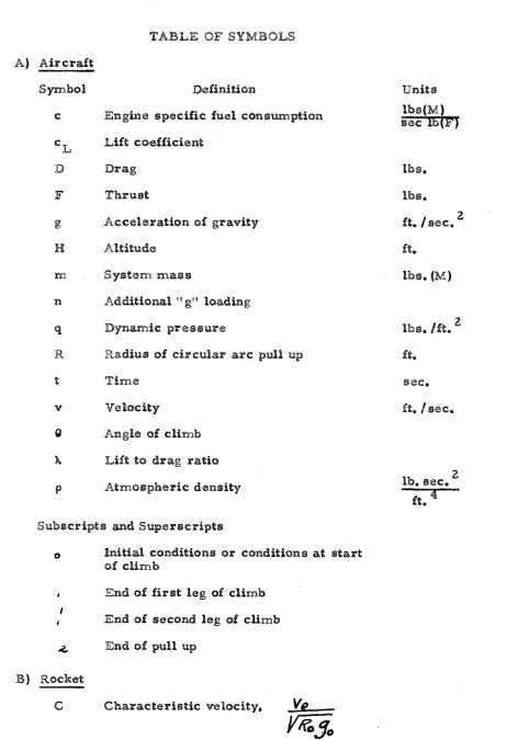
OF SYMBOLSc Engine specific $anal consmption
f3 Acceleration of gravity
H
AltitudeSy8tem D I ~ I S
OP Additional
''
ggs"loadimragDynm-ic prassure!
v
ve
loc it y8 Angle of climb
h Lift to drag ratio
Subscripts and Superscripts
o Initf raB condition8 or cond&ions at start
of ~ U r n b
4 End ok: first leg of climb
I
4 End af second Bag of climb 2. End of pull up
8 ) Rocket
Chaxac teriatic velocity, .
[image:5.572.65.527.43.718.2]Energy per unit -mas@
Specific energy, Thrust
Radius
OP
earth Radius of orbitCharactatistic time,
&-
E f b e c t i v ~ exhaust velacity
Tangential ~f.at@lli%e V V ~ % Q C ~ ~ Y
Payload weight
Racket weight Xocket fuel weight
xockab structurali weight Fayload weight ratio,
NR
Payload waight ratio per stago,
Wxz
.-.
we
Structural weight ratio,
WRS
Subscripts
-
unless otherwise noted abovs 0 Initial rocket c o n d i t i o a ~ft. E
be. / s ~ c .
f&,
I
see,libe,
lbs,
lbs.
Ibs,"
-
1-1, BNTRODUCTEON
T h e la~~iacHBing of large @ataBUtes into orbit by means of rscket propuP8iollz require@ m a t i - s t a g e rocket ~ l y s t e m s of l a q e tkrulrnt and weight, Ht has appeared porjreiBBe that by replacing
&he f i r s t stage of an all rocket @yettern by a lgtiag a i r b r e a t ~ ~ f g boost, the rocket thrust and weight requirementts, could be r e - duced. The a i r brsathing boost could offer other O ~ V B O U B advan- tages oves the all rocket system, The fact that the manned
boost would '$a ~ecccavssables should rspssdt in much Power ~ y s t e r n coat for a skafficferatly Barge number s f l a m c g n g s . Furthermare, there w a d d be ms areqdrsmant for the conrstruetion s f Pamching platforme which are required for a0 all rockat eyetem. Launch- ing of various ~ i e e rockets by the air breathhg boos& could be accomplished dthorag modSicatlsn of the boost system, Tha
air breathing boost also has obvious disadvaaaeagea when corn- pared wigh the a11 racket eyste;m, 1x1 particdar, the cost 06 an a i r breathing booast would bs Mgh, m d t h e dsveloglment of an aircraft and power plant for IaaancUng rcscketea at Mgh Mach
numbers wmld take s n w b e r of years.
The use ofE an a i r breathing bosot for lakusckPing gatel- fitea ha8 been consfrdered by a variety s f authors, Sandorff (1) made a co~g;parlsk~n between a three @gage rocket system and a
-
2-of cogst, rocket thrueto and weiglas, w.d B y ~ t e i m weight$ w e r e nlade for 0he two P a m c M n g achema@. Racket esato were based on Obe averags coot of the VSBEirsg rocket per popurd, It wag as-
sumed h. the analpais that an edes~png drplme guch as the 8 * 5 2
c o d d be mn?,&gited 4 0 IlawcB.1 the O w stage rocket, a d only modf- ficatisn coets ware estimated for the Arplma,
Mappue 92) discus @sd sxietftng af r breatEng power plants and their poslslibls u@e la an air b r e a t h k g boorst tsyestem far SabmcMrsg eate2llites or b a l l i ~ t i ~ sailes, mgh Mach number
engines were malyzed, and design problems w e r e e n m a r a t e d for such ~~llgines, The advantages of the. air bsreatMng boost
~syslem ware d i s c e t ~ ~ t e d briefly.
A more detailed aniellysie of the air boo~r; ~ y s t ~ m for launch- ing soteltlitee was made by F~errl, Mucei, Daskfn, and Faldn2ijm
(31, The problem considerad wae the placing sf lO,OEBO paundo in orbit, The air breathing boast WL@ a c g t n v e n i d r p l a ~ e pow- ered by d t s s b w n h g turbojets and fadet@. Gompa3~f~ons were m a d e between z~cket ~ y e ~ t e m and air boost e y ~ t e m s svbic$la.
Pamched Ohair paylo& over a range sf Mach a u m b e r ~ frorn 2.2 to 4,00
These p~adoue8 m a l y ~ e a 0 6 the air breathing boost Iaeulch were concerned with very partfcdar syratems %or which a detailed rasdt wa$ computed based upon a given flight p l a .
T h e aim of the p ~ s s a n t work was to mdartaka a somewhat more.
cruds anlbysis but Bs linvestigata ayetema%ic varfaejioraa in power
-
3-Ins &hi? preseat analysis the air breatMng boost was con%rfd- ered to be s turbojet. or dual z~eycle e n g h e powered alrrplaa, The rocket system analyzed in conjunction with the booat had two stages. T b s a $ ~ a , l y ~ l s consistad of ccompuang &he periormsnce sf $be air t a ~ o s t syslan2 for dglersnt B P ~ U B S of drplme a d rocket parameters affscting system gerfcprn~amce, The p e r f ~ r m m c e of a three stage all r s c h t Bystem was computed also for co1~1?psr$son purp01et3,
The! results of the amzalysis appear ir, the fa+m of graphs
shodrmg the effect of varying certain pasa~2eteo°rs,
Th@
air baa@% system was a d y a o s d for launch %i+fsch numbers from 2,69 &a 5,0, and, ~ B ~ E ? T E ~ P ~ Y , %he results are plotted vsrslus the Mach n u b e r111, ANALYSIS
--
The flight proQle en- visioned for the air breathing boost 1s shorn in Fig. 1, F o l 1 ~ d a gt&s off a d iaecele~iab%ion to climb spdad, o two step climb %vaa
made to the p d l up point followed by a puff up to tha m u i ~ m u m attitade attdnablls for lau~pcchishg the reeket system, In comp&- ing the akplme performanee, it was assumed that the engine thrust, engine opscbfic h e 1 C O P B ~ ~ ~ ~ ~ O ~ P , and the lift to drag ratio w a r e cerrtstmts, '$arm up, take aff m d a ~ c ~ l e r a t i o n %O climb
speed was osrs3u~isd to r e e d & in a fixed amow%* of fuel ccsassunisd
independent off tbe gesfoxmanca characteristics chosen for the
airplme, &a. addition, it was as@[email protected], that the drpBane charas- teristfcs did not depend on the Mach a m b e r of lamsh.
In eompukhg the ~ o e k e t perforrsancs burning times, ef- fective exhaaaat vetocitle~, paylo* weight r a t i o ~ , a d structural weight ratios ware %&en arbitrarily to be the same %OF each stage,
Also, the tistra~ctezlnral weight ratio for each stage wag asswed
aq-P to &he averall structural weight ratio. The energy posoessed by the rockst ~ y ~ t e m ~ at the and of bukn~ut was camputed i?lb if
tkaere w e r e no coaetfaag Between stagas, "$Be colcullatiane ware
made by c ~ m p a b g the kinetic and potential energises far a v e d i c d sowding rocket, Brag was neglected, and the accelleraUo~ of gravity wa@ taken as a constarn$; equal to the eoa level atdue.
Air Brsathicg Bosaet Pel.bormmce, --The balanea of forces on the
systte8.m f o r the climb portion sf the flight is ehown in F i g , 2, The
-
5-dadation of the t h f u ~ t axfirs from the fligb% pis&hs
F
and D ore the t b u ~ t and drag, re~pectiv@%y, in p s w d s , m is t& wmss in slug@, O i s 3 the angle sf climb, v i a the velocity in f"% !sacc anda:
i~ tbe t3r.na in Normal 20 the flight pathwhere
E
5s %ha POfi in pounds, Also,if the acesHera~on of gravity and ebe angina s p e c i f i c fuel c o n s u p - tian,
Ibe
,
are taken as constants, Didding equation 1 by aqua- tion 2 and er&lnstit&hg eqwtion 3 into the result, there i k ~ s b t a h a d the diffarazatid e q u a ~ o n-
6-far %he velocity at the end of $ha first l e g of the climb, For the velacity at the end of the second l e g of the cllfmb
lntsgraetiaag the eqwtion for vslacftg the alld;ftudes in feet at the end
0% the firs% m d se~ogld p ~ r t f o n s of the slim93 are found to be
A circdar arc pull up w a s cormaidered for the pull up ta launch attitafcae from2 $ha climb, The b d m c a sf forces on the sye-
tern i@ @horn in Flg, 3. The equatiana af matPsw, are
ielle~rag the flight pa&B, and
normal 0 0 tkm a f g M path,
R
iar the radius of the circular are in feet. DEvJidhg equatfan 10 into c;qutisn. 9 and mdcinng use of eqw-Since the time of pull up is short, %rsn3 twem$y-fow to t M r v m c -
c a n Be approxignats8 c18o6iialg.y by peplajt~hg the variable t in $has Last
-
term ~f aquaion $ 2 by a constant
4
approsrimately aguaE to&
f
.
l
.
If
this i e done, the velocity at the end cf pull up is2
f o n d to, ba;
where
A =
- e
\
/
and the subscript 2' denotes the end
of pull upo
Tho a'b$igieP;kk%c at the end of pull up Is /
breatldrrg bocs@t, dditional equtioxls were needad relating at- m ~ o s p b ~ i c d e n ~ i t y to arlatude and tho radius af the circular arc
pull up t o the velocity at the start ~f pull up. Fear the alt-itdes of jirnteaeest c h ~ tId8 an&ysisB the atmospheric density at the end of
climb can be represented very clcssely by the equation
3
where the density i a in sluas/ft
.
S l n c v ,2
P
,
where q is3
a
6s
the dywaxmis: pre$@ure in lbs, /ft,
,
e q a t i s n13
can be! rewritten oog
8 6 )A l s ? ~ , R
=
(~12
wheren,'
is the additiorul trg'g l o d i n g h p a 6 e dvt'
90
oa the aircraft :eat the start sf pull upo Substituting equation 16
puU up. mathene eqwtispn i s obtahed for lamch altitude:
In the eolutioxl of the equations for the air breathing tssst p e r f o r ~ ~ ~ e e , tha dpiarnaic prea sure PA the end of clin~b wa5 t&en
as 2.000 bs. l P t far all cases. Depending on the value of velocity desired at the end of climb, the k m c b alltitde could be estimaed
b y choo~irag the lift ccoeuicient at the end (4g pull up. This lift coeffl- cfent was &&en a@ 0 , s %or all case@. The angle ob Batasleh was
vailue of launch altitde aecarding to tks'launr~h M a c h n w b e r &a@-
sired, equation 17 was solved for the v e l s ~ i e y at the start of pull
I
up,
.
Equatfon 16 was solved far the alltjieude at the end af climb,,
in tbc solution of equation 17. Waving velocity and a l t i t d e at the ead a8 ePfmb, B Q U ~ ~ ~ O T P ~ 6 and 8 w e r e solved eimeal- tanaousilyEOE"
the time at $ha sad of each leg of the climb, Ineofviazg e q w t i ~ n ~
6
and 8, the3 velepeity arm8 akB18da at the end ofthe first l e g of tha climb were detarmbed atso, Equation 13 was @aSv~d mxi; f a r the velocity at t&s end of pull er~a,
.
Tban tEts lift ccoefficfsnat at the and of gdll up wae co~ipaated fromAny variation of terminal lift coefficient,
CLil
8 from 0.5 wascorrected by cbrragissg the value of l a m c h angle, e~nd t h u ~ launch alltitrado, Bamch ve8od=i&y, and fha addbtfanal "tgg' Boding at the Bameh point.
Rocket RrfFormmca,
--
The energy necessary to bring a eatellitke into a clrcuhr orbik arowd $ha earth eomaeisks of its kinetic and potan~al energy, Thus,where
Xo
is the radius of the earth. r is the radius of orbit.vg
i a the tangential velocity of the satellite andE
is the energy per anit ma@@. Far a cji.scuBar orbit the (centrifugal force of the eraeel-&it@ must balance the e s ~ % h @ rs gr avitotiormsl pull, Tberofora,
2
2
5
.
since9
(+)
,
Substituthg eqmtfons 20 and 211 h t o equation 19, the required energy i e farand to be
Nsrnadising e q u a ~ o n 22 by dividing by the e n e r g y meceaBary $02 a circdar orbit at the reu~face sf the earth, the specific energy,
E,
The problem considered was the placiang sf a satellite in a
200 milla circular orbitt, Thus, E
=
1.047,The equation esf n~otfon lor a sapaadistng rocket is
where rn i @ the rocket mass in slugs, and
25
is the effective ex- haust velocityLq
8. isec.. Drag has been neglected. T&dsag g=
go, equticsw 2 4 %nBegra&as towhere
m
i a ~ l the idti01 r ~ c k s t ma@$, Sut- l 1 -
w%sere the ~ u b s e ~ l p t b indicate@ bornsat conditisne, The tsbB ra&ot
weight is
where
we5
i a tho structural weight.M/
is the fuel weight, and*f
%
is the payload weight whkh includes structure for payload. lntrducing the strueturnl weigN ratio.P
=
g s and pay-Wac
f%f
load ratio.
.(
=
&,
equation 26 can be rewrieen. m a d n g use of squation 27, aswe
S u b ~ t i t u t h g itnts equation 25 and integrating, the velocity at the end of burnsa of the first aeclge is
S l n c s it was assumed fhataz&
.,&"
.
that4,
=
u('
=
a( andthat
4,
=
fbz
=
5
&
the vetocity at burnout of the second stagebecomes
E~tagratfon of equation 25 twice and subatitutie~n of the apprcsprrfata
By
u a h g equtio8as 30 and 31. %he specific energy of the s y s t a n ~ is bomd to beE=E.
f~c
~ f i -
'&/@J-
+
J - Z I ~ I ~
+ Z V C
/,(~'jl~)
9.4
-3)
%
f
,
where
6
=
.
the specific energy imparted Lo the sys-Ve
andT =
2%K T e
By a sfnsi"a.~~~ development the specific energy of a three rocket system i s
In the p e r f o r m a c e calculation. was determined from equation 33. Thus. a1 could be datermined from equafion 32.
VC/
4
and
MRL
were then compaed from the expressionswhich r e e a t from solving the di4erentfal equation
F
=
-A-
dm*
9
0
U'P
and making the appropria$e e~ubstitaio181e
The weight cbracteristics
d
the ~aystem w e r e csaznputed by subdigrjldhg &he syseem into five @omp0n81%t1; xlan~ely, rockat, air-plme fuel, Aspplane fuel t d s , Grcrraft ~etructuse, and engine@.
The s&rractaa~aB weight, w/hich included c r a w and equiprnant weight, waea t&en as a con~stat. Aircraft fualt was broken down into three cate~gorfes: fuel far w a r m up, talc@ of& and acceleration to climb
speed; fuel for climb a d gull up; 4 fuel reserve for lmdhb, Fuel tank weights were *en as a g;oaastmt percentage of the fuel weight, Ff~aBllgr, engine weight8 were ~hh88en which w e r e ~g~mp$3b$-
Ghofcs af Parame$ers.
--
For the air breathing boost system the folbwiolg paraxieter s were varied in the analysis to %how their eS-fect on sys%em performance: engine weight $0 thrust ratio, eaaghe @pacific fuel con~smption, airpEme thruet weight ratio, the angles of climb, airplan@; s&rue&.caraP weight ratio, a d the 'fib t o drag ratio,
R0&63& paramet&reS varied were the effective exhaurS& velocity and
the burning time, The ather parametera k a d n g a effect 0x1 ~ y ~ t e m performance wt?!re considered fixed t E x z ~ u g h o ~ t the an&y9a%do
fn corsnputhg the racket perferrmmce it w a s assumed that $ma% for warm up, fake off, and aecelea~atiaa to climb speed was two pas cent of @.he take off cveipht. The fuel for 'limdhg and re-
serve was $&en as five per cant of the drpBme stzuctural wefgZst plus e n g h e weight. This would be apprlaaamataly $our par ecn8 of
l a d i n g weight. The fuel taaridrs w e p a considered to weigh fFSarl; per
cant of the fael aaveigu. This fea a suaadard eatimate for gasoline and 3P type f~ele,
$Be etruct%zral weight was taken a@ twenty-five per canat
of %be $otal weight, a percentage which appears apedi~tfc when
compared with ~ s m s 0% the day bomber airctdt. The c r e w
and eguipmed weight was hcBuded in the structurd weight, Tor the size dsplaae gequired to hunch a Bkiarge satellite, the c r e w
(?and equipment weight weau b e o ganjiflar c~noide~atfon, However, for s m d l s r afrplmes the c r e w and ~ q d p m e a t weigh$ w o d d be a
greater parceneage 4 ~ s t e m weight. T h f ~ f~ 8 0 becaase the crew
-15-
2
The wing loading was set at $00 l b ~ . / f t .
,
a value common$0 n~adern ape~a%bon a f r e r a o
The l i f t t o drag ratio was taken as five Xor 'both l e g s of the climb. Experimental evidence indicates tha$ high ~x~peraanic air-
craft can be deajssed bsp m ~ f m m . lift to drag ratios in excess
of
five. However, in the analysis $hePfft
coefficient dunring a majox portion af t b ~ second l e g of the climb is e%igh$2y %elas than 0.05. Thus, it would appear that the value sf fibre for lift tto drag ratis during climb i s somewhat ~~slPn~i&e;le, F o r the pull up the lift 86drag ratio tvas %~$kan a$ t b e ; a .
The awglhes oB: climb were chossn $9 that the air b r a a t b g
boost aecelerate?ld continually alcrrz~ the night path during climb* Thus, the c h ~ i c a of climb a n g b ~ ~ s was dictated largely by the g h r n ~ t
to weight ratio. The climb mglle fol: the second l e g of the ~ f i m b was cksasen Pam than that far the Piret Peg in altl casss, A gtwo step
climb v f a ~ c h o ~ e n ~ so tba% &be same aeslgltes of clfa~b coulbd bs used over the Mach number range conaidered f ~ s e each c a m ,
11twas assumed that a lift coefficient of O, 4 could be attained at the lawek.1 b%ac%a aeas~rakteee~.
To
obtain the m d = u w ; Eauwch angle,the radius of g a l up w s d d be inereasad a@ a-=9-=Emm
BSA
ccssfficienf; waaa approached in on act-Z gall1 up. Singla a ciscdan. ore pa131 up-
16-up wao included fn the. a n d g s i ~ since 1 a w c b g of the rockst at the low mg8es of c18im1b could impair the socket p e r f c r m m c a .
The rockst ~ t r u c t u r a l wafghf ratio has a I n r g e effect on the
anqo-t sf payload that can be placed in srblit %or a given 1 y 5 t ~ m w e i g h t A vdue of 0.05 w a ~ chaeen
$Be
rocket structural weight ratio, This i@ a t & a b b l @ %OF a d.Ilfq~d prop@Uant rock@% %apith 10winitial accalerationea. This aceeleratioa varies inver@e11'lp with burning
am@,
For the stmdard case burning tin-A@ waa taken as120 second, s%&y afseconds peg stage, Far the Lhraa etago dl rocI*cot
cystsm, tot& b u r d n g &iwLe was take= ae 188 second@, 60 second@ per stage,
Table If absws how ebb?: o t k r paramatera werd chosen fn the
analyaf~ and bow these pbilrarnetera ?;ere ~raridd, Case P was takalen as the stmdard agafnbse which all o t b r c a ~ a l w e r e cornpard, h c a s e @ IlJi through
V
$he ratio of engine thrust t o eystana weight wasvaried far egcos2parf$se purposes, The lift to drag satis wae reduced for two separate value@ of angina t b u o t t o systam- weight ratis in case@
VI
and VXI, The effectof
reduced thrust during p d 1 up vTaePnve stigated in ca@s VEIL Cases I X axad X involved the c h a g a in angles of climb and in airplat~e e9t;reuc$asrd we3gE28 ratio, respectively, The effect of anabe &rubat &O engfne weigh* ratio and eklgiz~s O P B C ~ ~ C
fuel consumpBfoo waras svalwted in eaees XI through XV, Rocket
effective a x b a s t velocities w e r e c h ~ q g e d fe case% PCm through
2 , Fiiadily, rocket burning time was varied in e w e >C$YS,
Fsr $be s t a d a r d case the tH.aresat t o ays%em weight was c e t
at 0,75, This 6~ very Mgh, but $8 w8@ chk)@en airice prej$imhary
fas poor system pekfornlanca, The angiae thrust '88weight ratio
was t&@n as O . B Z . A mtuoz, of 2.5,
,
w a s ch01@n for %hi!? engine s p c s f e fuel sonaun~ptisn. The@@ value a, arlthaugh s ~ m i e -what ~optimiatfc, corse@pond hbrly
WBU
to t h e e for d t ~ r b w n ~ g turbojat engines now in use,An
effec~are exhaust velocity of 9,000ft, Bsec, was selected for the rsclcet c o ~ r e ~ p a m d 8 n g t0 apn oetua1 specific hipulse 0% 280 aecasads. S b c e in p r a c ~ e e the a c t u l sge-
cific Palpulse i a a b u t nbetfy per cent of &he idaai, &he v;gi%ue C ~ S ~ S E f FA r;.a&i~.tic today aaly for Uqdd prapsfl- focckets,
It, and the a g l e of launch as tlbrty d a g r a s s r c ulted in a launch
angle sf bunch ao t-arty degree@ for %he stmdard casa, 10 fomd that the v ~ P o G ~ Q at the end of climb W ~ B 3888 f t r / @ a c e farem equa- tion 13. T ~ B first term g3P eqwtian 17, the dtltude at the end of
climb, waes fousd t o "ra 555,600 15t. Next, egmtione 6 and 8 were solved @ i m d & s n e o u ~ l y for the times at &ha end of &he dfatet a d sac- ond l e g s 0 % the climb, These w e r e seventy m d two hundred ten seconds, The vebcity altitude at $he and of the first l e g of the
C ~ ~ H T I ~ w e r e r e ~ p e ~ t f ~ @ P y 1360 ft. beec. m d 26,000 &,
,
both .values being o b h h s d iol &he solution of @qwaon@ 6 a d Fr6m equation1 3 the velocity at the a& ofF p d l up was f @ u d to be 3865 ft, /rsec,
-18-
18 it waha fomd that $he lift caajrfb~ien& at the and of pull up was B 0 5 Q B , Thus, the altitude of kauxl~b and the sngla of launch were chosen csssecOBy, Fuel consumed doarfmg the climb and pull up w a s c o ~ ~ p u t e d from1 equation 3 and was g o a d to be 1$,58 per cent of spvetemi weight,
H a v h g that: velocity at l a m c h anad the l e u e h altitude, the r ~ c k e t payload wsf ght ratio per stage was caBsulalo;d from equa-
tion 32 after solving aqutioan 33, The payload ratio per stage wag B O Z H 8 , Therefore, the ovsralll payload ratio wa@ 0474, The ratio of roclcet weight ts payload weight was the reciprocal sf ,0474 OBP 210 lo .From equation 36 the weight sf the second stage, of the rocket per pound sf payload was f o a d to be 4,6, C sing aquation$ 37 a d 38 the rocket thrusts per pound sf payload w a r e cow~puted as 88, O and B7,7 for the first and aecsnd stage@, rs- spectfvalg,
The fuel %or raturn and B a d h g was computed as five per
cent of the engine weight plus structure weight or I,'? per cent of take off weighta Thuso fuel for the m f ~ s f ~ n wal 16.28 per cent of system2 weight at take off, Subtracting the ragis of the ~ U - I I of
engine, etructure, fuel, and fuel tank weight to system weight
$porn one, the ratio of rocket .&Q sy$tem ~veight was found to be Qo48911, Thus, system swsfgbt at take off p s r pound of payload
w a s 4 3 , 1 ,
IV.
RESULTS AND DBCUSSIBNFor the etmdasd case the velocity, altitude, lift coefficie&,
and total pressure w e r e computed a5 a function of time for the Bamch
&Tach a m b e r of 4,Q9. Theac are plotted in Fig, 4. The rise in stagnation pressure with veBscity along the flight path, as shorn
in Fig. 4, would result in an increa~sd air weight flow through t h ~
engine at the bigher egeeds even though dsfuser sfficienqy wou1.d decrease with epeed, Thie could conceivably eowteract the ds-
crease in heaWddditiesna per pound of air flaw with increased apced.
T b u ~ , with a properly designed e n g h e , with variable diffuser inlet and nozzle exhau~t, %he thrust could ba niaisa$ainad nearly constant UP to the pull up point, Thrust would definitely dacrraalse d w i n g pull up a@ indicated by the sharp drop in total preseurs, Ht is noted
oleo that system speed actwlly irncrsa~es during pull up. This is
because of the high $ b u s t to weight loading. Becouso of the very sharp rise in lift coefficient near the end of full upr the launch
altitude and Pamch angle vary vary little v~ith a change in the climb
angle for the second leg of the climb,
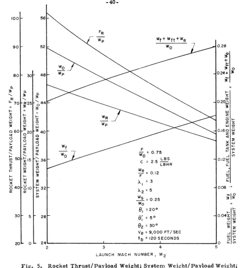
In Figo 5 esme af the results of the ~aolutbon of the perfor-
mance problem are shorn for the standard cage as a. fbera~-ction si
tBae l a m c h At";aeh number, Although plotted up to a lase~nck Mach
numbsr of five, $be rersulta are not particularly significant past a lamch Mach n&mbek of fouro Turbojet engine6 are %imit~d by tern-
peratrare to operation a& March nm-sbera not much in e x c e s s of b u r ,
Thus, for launch Wiach numbers 0% $live and greater, rarnjats or
other type engines would have to be used in conjunction M&h turbo-.
-
20-for the higlaar ?+Each nun--hers of launch. .At a Mach. wm3ber 08' five the stagnatioa temperature is approxieat s l y l SOOO F for altitudss above the Ercapesgause, An aircraft e t r u t t w e designed t o withstand the temperatures encouatered at such 3 Miaeh n-ber would F P S C ~ B - ea~iOy be haaspier %Ban one deeigned far o p e r J i o n st ls~6r'ar speeds,
It is eaen in F i g , 5 that the ratio of racket weight to payload weight is reduced 'by approxir~ately twenty-four per cent if &he
racket is lamchsd at a h5ach n u m b s 4 04 four in~tead 0% a Mach n m - -
ber of two, 2It was f o m d fn the walyois %hat the reduction af rocket weight with lawich XCaeh numbsr depends ailmost entirely on launch lviaei;.a number. The altitude of launch &fcc$s the rocket weight
sllightlgo coatributbng only t o tbs epeeifis: e n e r g y launch,
The ratio of B y e t e ~ i weight to payload weight also decreases with M a c h numaber of l a k ~ c h @ven though the airplane wefyhh g o s l
up, Al$&'~eaug$ the d e ~ r e a ~ e rfiight not be as great a$ soboqm-, arris&e@n p a r cent for lamcb at a Mach nurfibsr of four co~mpared to a M.ach g-aumber two Iawi%~& it is edden-at that the M g h e ~ ILa~*oa~ch W!ocb a u m ~
bar yialds E ~ O ~ O B a v ~ ~ a b l e results,
two launch, while fox a Mach number Itour launch, i t is slightly in excess of fihy pea cant,
Zna the design of a turbojet engine the engine specsic f u e l
conrs~2imption can be improved a$ the ezcpenee sf engine weigM to tBru~39 ratio, Caeee XHU, XIV, and XV are combinations of engine weight to thrust ratios and engine specific fuel c o n ~ ~ m ~ p t i o ~ ~ $ s \$rhic?h'B r e g r e ~ s n t the optimux~ in turbojet engine design today, Gasse XH and %.I3 represent engine@ of poorer p~rf~rs~2aaacs a d a r e C ~ J F B C - t e r f s t i c of engine8 now o p e ~ n t i o m l ,
The effects of varying the@@ two p a r a ~ ~ a t a r e , engine v~;reiig%%% es t h r u ~ t ratio and engiae specific feuel ceansaarnptisn, are a h a m in
F"Sg8. 6 , 7, and 8. h Fig, 6 $Be O ~ V ~ O E S S resalt is shovm that the systems having engines with the bast sgecSic fuel con@um,ptisn u @ e
-*
$he liaa@k fuel, . ~ n e difference becanles greater at &he Mghcr Iswch &Tach n w i b e r s * The difference in fuel reqdrernent~ for
s y ~ t e n 2 s having engine@ with the s a m e specific fuel ~ o n s ~ m p t i o n i o due to t h e amiovat of fuel required for r e t w n and %=ding,
$he fael r e q ~ i s r e n ~ e n t a for the sgyeteni b ~ n g the engine of bast specific fuel cesnsmgs&ion, 1, 1 Ibs
,
are about thirty-nine percent Bsas % h a thoso for tha Bystera wieh the w o r ~ t specific fusl conou~~ption, 2, 5 Ibs
,
for s launch M a c h number of two, At M a c h nunher .four the difference i@ about forty par cent,The effect on engine weight, fuel, and fuel tank weight
is ~ h o w n in Fig, 7. Here it is aean that the angines of Bower
-
22-l o w launch Mach number$, F a r lower s z l y s t a ~ ~ tkrubt3t t o weight ratigao, engines with lower specific hue1 consmption and E g h e r weight to thrust reatios would eomp are niSpre: Pav~rablj.%vo
The sffact of engine wef ght t o Bh~eaog: ratio and specific fuel
colnsumptfsara on system frveight to payload weight ratio 1s shorn in Fig, 8 as a. fmction QPP Itagg,""~ckl Mack& n u d e r , The effect is quite large, A reduction of about eix%sen per cent in systewa weight to payload weight ratio i o obedned by use of the best engine, weight
to thrust ratio of 0* 08 and ~pecific fuel consm@fesn of 2 , O Ibcs, #1b, hr,,
comnpared to the worst engine, weight to thrust ratio of O, 20 and spa-
cific fuel ~ ~ n s u x i ~ p & i o n of 2. O %b IB
.
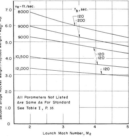
T k ~ e is for a Bam~cB Mach nu*-- bez= of two, i't a lamcch Py'ach number of four the reduction is closer ts fifteen par cent,Tho effects sf rocket effective @xh;zust velscfw and buraing
time sen sy~%c?m performance are 8 h 0 ~ n in Ffge. 9 through 16.
TEsase two effect@ a r e by far the greatest of any considered in the analysis, In Fig. 9 sqrstsm tveight to payload weight ratio f @ plotted
versus launch h%ch nwbesr for eftectiiva e x h u o t 8reTaciOies varying from 8, B O O $0 32,000 f t ,
/
~ e c . and far the s n z case where burgtinagfkni~: w a s taken a@ 280 seconds.
I%
is noted that tho higher Mach numbers of launch are e s p e c i d l y dasfapabHe when rocket parformtansca is poor, For a roeket effective ex'bust velocity ~f 6 , 0 0 0 ft, /r%ec,, a $ystdz2 weigh% of 580, Q O O poughd~ would be re$g&giaged t o lamch a5,920 pomd payload into a 200 mi%a c i r c ~ l a s orbit under tEae assump-
ticans sf this anaZysIs, For a 3~%acPa nm~~bese of launch of four egretem waight would have $10 be only 394,000 porndo ts place the same weight
a payload of 23,400 pounds could be placed i n orbit with a system waigkt of 500,000 p ~ * - d $ ~ rocket launch being at a Xach number of
two,
In F i g o 90 the s y s t ~ x n to payload tnteight ratio is plotted versus
effective e:~baust velocity for duferent values of Paunch Mach num-barkp,
%he three e b g e all1 P ~ P ~ = K B & gyetem f @ plotted sna the graph also. It irs seen that the boosted rockat system^ bcccsri1e5 more dssirable when
rocket performance i.8 poor. A t the higher effective exhaus% velscf- ties the air breathing baes t systarn omp pares less favorably with the all rocket sy~ters:, For a three stage 921 rocket system with a burning tisce of 300 seconds and an effective exhaust velocity of
9,000 ft,
/
s e e .,
the s y s t e z to payload ~ v e i g h t ratio 1s 5 1.6 w d e r theas$un:pthons sf this analyois, Fslp the two-stage boosted rocket
with burning Bine.e of 200 seconds and an effective exhnuat velocity
sf 9, OBlQ ft. /o;loc., tht3 syetent to payload ratio is 53.6 for ;a Bameh
Mach nun2be;r of f8~29~. Thus, the boosted rocket s y a t e r b also corn- pares saxore fsvoseably with the 111 r ~ c k e t s+s.&erfi when ir.ii3ial accel-
erations of -the lirst stage rocket are IOW. %his i s the case fox* the first stage sf an all racket sy$tern be?caus~ of the control problems after launch, and because low acceEeratfons art7 T ~ Q L S ~ T C ~ iniB5aIly if tho rocket sts~ucturali weight ratio it3 low, P l s s , the first stags of all socket system is less efficient because the rocHce% is ex-
h a u c t k g against the back pressure e8f the akzosphsre, and rocket drag i o at its highest in the denser air of the lowar atn~osghere,
In .Pig. %
B
the rocket to payload wci gkt ratios are plotted v e r s u s launch M a c h number for th$ diaereat effective exhaust ere--
24-roeket to payload weight ratios vcr8cs effective exhaust volocitiaa~
for the duferant la-3ch Mach numbers. For an effective exhaust
velocity sf 8,00628
A.
/ a e c , , tfka rocket ta paylaad weight ratio forthe rockat bsg0str3d ta M a c h fnw~-~ber ~ O U J P before lamch is forty-eight
per cent lass &ban the ratio f ~ r a three stage 91% rockist system. For am effective exhaust velocity of 10, OQO ft.
I
BOC.,
the r s d u c t i ~ a ie forty-two and one half par cent, Tbus, it is demc~nstsp'atod againthat the boost system c o m p a r e s m ~ o r e faBvora&ly with the all rocket
system when rocket p r f s r m a c e is poor, It is noted also Ohat t h ~
iaweb Mach, nux-sber has a great affect on t%e Bysten, t o payload weig11P ratio for the boosted rocket syti;tem. Again, the sffeet i~
more? pronowcad when rsclxet perEormanco is poor.
Figs. 13 and $ 4 show the effect of effective axhaa~jlt vslocji- ties and 'kPu~ni.~%g times on tho oeeond s a g e ~ o c k e % to payload \veight ratio. Gsrnparfng ths weight ratios for the boosted and all rocket
system, it is seen that Ohe reduction fa weight of &ha second stage
rocket for the boosted systarn is greater thsn the ~ a d ~ c t j l o n for the f i r s t stage, TMa is because the payload weight ratio p e r stage i e greater for the all rocket systen?.
The rocket thrusts to payload weigM ratios ars carapared
in F i g s , 15 and
16.
The ratios are not tha same as the rsclcat to p a y l c d weight ratios b e c a w s of the dllfclrence in payload ratios per stage batwean &he bsoeted ayetern- and tha all rocket syo$eE.FOF the first stage initial accelerations of the all socket s y s t a ~ ~ are approximate1y two tfw~ee the gra~tatinnall accelerationo For the
-25-
practice the thrust requirornezate for the rocket lamched fromA t h e air breathing boost would GO dawne and tba con3psrison with Bhe all rocket s y ~ t e m ~ , as sba.tm in Figw 186, would bc more favorable. WOWPWPBV@~,, reducing the initial rocket aece'feratiaana of tho boosted rocket would reqaairs an inacreasa in rocket m d oystem weight and the ~avara%ll. perfolp~-ance of the %3~0st,ad rock@& systerfi w~d~uld deteri- orate, A s sboww In Fig. 16 the thrust requirem@nPo f ~ r the first
shags of tha air boosted rocket are less by a v a r y small n ~ a ~ g i n if
the booeted rocket i a P~-3mekded at a >#tach number of two, The re-
duetiean in thrust r e q d r e w ~ e n t o is appreciable only a$ the higher l a m c h Bdach n u r n b e ~ s ~ Again, the air boast systara compares more favorably wben rocket gcrforramce Eo goor.
The effects of system Oh~uglS: to w e i g u ratio on the perfor-
manes of the air breathing boost system ~ F B ~ P O W ~ B ia Figs, 17
through 20, In F i g , 17 it is seen that $ha increase is odrplaac Pus1 ~aqnirercen&s i@ appreciably only frsr the case where &ha a i t p l a s
thrus9 to g y s t a a l xveight ratio is rsduced to 0.25, -At a lacr~ch PFach B U X F ~ B F of POUP, the fuel, required is twenty-nino per cent sf sys- %arz weight if aairglsna thrust to ayatew3 weight ratio Is Q o 2 5 , \vBfle
the fuel r s q d r e d is only s h t ~ e n p e r can6 s f syetaw; 4veighf if air- plane thrust to systa121 weight ratio fra 0 . 7 5 ,
The sum 0% fuek, fuel tanks, and engine to system weight ratios is plotted against launch Mach nnm~ber h F i g , 18 for the
range c ~ g airplane thrust $0 oys9ez-n wef ghh ratisso considered, Ware
it is seen that tb@ effect is Earge 8 ~ 6 1 ~ for the case where engine
-
26-for acceleration si the airplane i$ eo saxall at the low thrust loading, Figs, 19 and 20 $how the effect of airplane thxss~t ts @yetem weight ratiss on syatarn to payload xvoight ratios, In Fig, 20 it is cesn that best perfotniaaca is obtained for power loodings greater
than 80 5% and less than 0.64, As seen 1111F i g , 20, the ~ l p f ; i r ~ ~ w : ~ O W B P
loading increases with f a u c h M a c h n w b e r e For optlm-aa$xi condi- % f ~ l n s ~ " g p t e n ~ weight t s payload weight xatia is reduced o h t e e n per
cent if launch &lack n u m b e r i e four instead of two,
The variagis~~i, in tha al%itude at the end 0% the first Beg of
tha c l i n ~ b as a fumtion of Mach n m l b s r is a h o m in Fig. 2 1 fop the five dufereat values of thrust to system weight ratios chosen in &he
analysie, I t io n~aeed that as the Mach n w ~ i b c r of lawch iea heseeasad past throe, the major portion @tf the flight is along the second log
of the.? c l i ~ ~ b .
in Fig. 22 it is seen that the gain fn altitude during puP1 up is agprcaA~-raataly 30,000 ft, and is eaeentially i d a p e n d e n t of launch
&tach num-ber, P"- o the launch &:a&. nuwbbar is i n ~ r e a s e d , the
launch altit-&da increases but at a steaalky decreaakg rate, RBtB~ugh the gain in altitude is essentially fndepaadent of l a w c h h?ach numbas, the angle of. launch i o not a@ is ahown in Fig,
23, In this andysis it was fomd that the angle of b u n c h depended
on lla~3a;h Mach amber only, In the actual case it =would be 8 a,fwnc-
&ion sf airplajne f h r u ~ t to oyotem weight ratis also, Since a circular
arc pull up was cansidered in the analysis, the additional ':gBf lead- ing on the airplane varied as speed changed, but the lift eaefflcis9ak
necessary for flight along the cfrculrar arc was l e s s Ohan two at
the end of pula up, as low as ona and s n s b l f , ~~'ih.ile for tha h t g h r
afrplme thrust: to system weight r a M ~ s , the value was in excess of two in some caselsa. By increasing the radius of -pull up, the angle of launch could ba increased vary slightly in the Batter case,
Since the ~ ~ a x i m u m i laweh angle far a launch a& h4ach ntam-
b e necessary to isas~ease the attitude of the T Q G % C ~ ~ ~ y ~ t e m after 1auach at Pdach nwzbere of five a d higher in ordar t o obtain opti-
5;ngsp"fi rockat p@x$gdrn3axaea, .hQ the law 1~:ach n ~ n - ~ b e r s of Zauxlch
this wouM not be necessary,
The change in speed &wing pall rap d e g s ~ d e d only on t h e l a u c h angle and the afrp1me t h r u s t to ~ y s t c z 3 weight ratio, This c h a n ~ e i a s h o w in Fig, 24 wBare $he ratio of 1~iae;g.h namber at ths and of ~UITCO to BLach nun:bcr at &Be end sf pull up is plotted
correspond t o lower %amch 3&aeB am-bers, it ibs seen that the HOB% in speed during pull up is great only at their Bower Eawch Mach nusn-
The tiz-~c., for climb and pall up is v e ~ y short for the s y b t e r n ~ with high po%ver Poadhgs as is seen in Fig. 25. Onfig Psr tba power Boodis~g of 8,251 does I t baccsme apprgtcitabb.
-28-
Bamch Mach n*afiGer cf two, The irncrcos3e is 2 . 2 per cent at a Bamch Mach rpambet sf five, T h i s is showarr in Fig, 26, Far the airplane thrust Qca Bystam weight ratis ai O , S o , the fael cowsmip- tion increase f s two per cent sf B ~ S ~ B Z B ~ ~ . gross weight at I E ~ launch &4ac%a number of two and 3 , 2 per c a t ~ t at a I l a ' ~ r n ~ H Mach number of j%fv@r The effect o8a sys&em to payload weight ratio is shorn in
Fig, 27, The redtasstian in 1st to drag ratio ha8 a greatkjr affect
on the sgrotaa* with O h l o w e r airplane tbruab, to system1 weight
ratio, For the tw0 cases studied the affect, although signiii~~3aa%, i~ no& t o s lasfge, At ;a h4ach number of lawich of five hha reduction sf systarn to payload r a t i o i e about f i v e per cent far the case with tBt.u&t loading i:oP O,50, T h i s would b e e o r ~ ~ a gseaesr for lswer thrust
loadings when there l a less e x c e s s power available for aceelera- tieen 0% the a i ~ breathing boast. Th8 redaced 83ft :to drag ratio has
tho added eifect of sMf%irng the ca@irmuna power loading carve in
F i g . 20 to the right,
Tho effect OD. fuel consumpti~n of increased structural weight and of di%Perenzt c l i ~ x b m g l a e irs shown in Fig, 28. Xn-
ersa~irag %he drpliane structural weight ratio increases the fuel to oyotem gross weight ratio by a.pg~o~dmately 0.2 per cent duo ta the increased amaunt of fuel needed for Pmdiag and I O L ~ S V O , CBmging the clin~sb mgkas to fitteen a ~ d @even degrees decreases the fuel conrsun?p%ion, the xn%dm~mi E % E c F ~ ~ B ~ being approximately
one per cent of sy@%e;g?;~, weight at a l a u c h Mach 1 1 ~ ~ f i b e ~ " 06 five,
- 2 9 -
T h e efieet f o ssqa%l. The increase in system to payload ratio 5s l e a 8 than one per carit for the range of launch Mach n w ~ b e r s eon-
sidarsd, The sffact is greatest at %he Bower Mach numbers of
laemch &2bth%r~" $he launch angle is graaeest, TMig: ~bservakion JUS- BSifEeo the as@ump%ion of constant thrust for
OP
the i n v e ~ t f g a - tion*The ~JHJ$~@ITL BO payload %v@ight rakfss far changes Hn airplans
structural %~$cighk raEPks and angle@ sf c%fn~b ara p l ~ t t c d in Big, 29 a@ fune=$%on@ sf ftamch Mach aws"iberO Ph 1s s ~ e n $ha% an f a c r e a ~ 8
in %he airplwe stfpu~tura11 $$r~ight ratio of five per C O ~ $ i n ~ $ e t ; t s e ~ the ~ y s t s - m $0 ~@yHoad ratio approxl~*akely nine p e r cent at a
laeach hkach n-ber of two and twelve p e r cent a0 a Iakznsh num-
ber of five. The efferet of changing the angles of c1Pxr~b is omall,
-
30-V.
C43NCEUSXO>3SThe analysis c ~ f the air br~eat8.ning b&jtk48% s y ~ t e r a OF $a$allite
tiawch reveals that the satio of rocket weigh$ "b paylaad weight
depsrsds @tsongLy on the AIach nurcbsa of kaun~I%, F o r a two stage aoctqet laasncl-ned at B~Zaeh number $we, the rocket t o payload weight ratio is 28, 3 for the ~Bandasrd c a m , By Ilamchfag at hcach num2bar tous the rockat to payload weight ratio f a 21.4, a reduction of about
twsnty-feaur per cant, For the t h x e ~ ? atage a11 rocket system the: ratio i@ 38.0.
The airplwe weight percentage goes up as the launch &/caeh nuraber i s increased, I-Iawevar, becaersc of %he stsong decrease
in rocket w3ighft. the syatem to payload r a t i o goes down as $ha
bfac93 number of launch Sre incroaoed up 60 fsur. For Pawch at Mach aumbers in Q X C B S S of four, the. analysis Is not strictly accu- rate since no increase was made i n afrplmc or power plant COXTI-
psnant weights. .For Bamch at 3Lach n m b e r two, &he s y ~ t e x n OQ paylaad weight ratio i s 51,6 while for h u n c h a% &Lac$ number foul;.
the ratio is 43.6, a reduction of about s f a s o n per cent, These rit4tH01 are far the etandard case, The all racket system weighs
less B I is seen Prom the rocket ta pe%yl~ad weight ratio meriz$fgaa%ed
above,
Tho a9rplaa to rocket wsigM rakio varies from ,just over forty per cent to j u s t under efsztgr p e t cant, depending on the 2Lach n-ba~ of launch and the performance parazx1etero ~ C ~ ~ S B T I L far %be booat ~ysrtsm, For Launch hzach n u r l b e r s of four it appear8 that the syst';st-si_ to rocket weiglxt ratio cancat be reduced much bzlaw
TBB coxriparfsc~zz of the all rockab: eysta= with the air boost
~ystaltrn P ~ V B ~ P I ale30 $hat kha comparison depends on rocket perfor- mazlce, The sir boost: ayatara. c0mpake8 ~ O P O fav~r~z'bity when rocket per$~rrr~&~r%ce fa poor. '~Vitka afgective e x h u e t veslioeitlies of 8, GOO $to
/
O ~ C O , the analysic~ shows that the cjiy~tem to gayload weightratio for the a11 racket ayri;$sm is 6 3 , 8 , FOB" the air boos& aysgem the ratio is 6 6 . 5 at a. lame$ Mach neam~ber of four, For aarn affective
e x b u s t voiocity of E
I,
000 ft, /see,, eorrospoading to on a c t u d specific irk2pulsa of 342 ~scksads, the ratio of syrste-m weight t o pay-load wisreigkmk, i s 119,0 for the all socket system and 25, O for the air boo@& systcaa when the roe1cct i o llamcbd at Moeh r;llurcibar four.
Thus, as better xocked: propellant combinations a r e developed, the admatages of r e d w a d weight and thrust for the air breathing booat
The choice 04 anginas %or the air breatbing boost %as a large effect OH^ ~ y ~ $ e p % ? p ~ r f o r ~ m a n ~ e , B @ c ~ u B @ the time sf flight
is short, it is desirable that the engines desigaed far the air breath*
ing boost b v e low waight at %he e x p b n ~ e of engins apeckfis: fuel consumption.
The r e a u l t ~ of the m a 1 y s i s show a%sa that the a i r p l a ~ e thrust t s syetsm weight ratio sheasklid be greater than 0 , 5 0 a d lass than 0.76, f Xthsugh the effect of g~%vnur loading is very small for
power loading8 betwean
Q, 40
and 0 , 7 0 , the effect becomes greater oueside of the Lqacatad r a g e , Fcsr Low power lotadiiepge fusl con--
32-added engine weight causes degesfioleati;ion i n overall S ~ E S ~ @ I ~ ~ C F P Q F - manee.
The s eductioa of lift to drag ratio has Ise s eif sct on overesll
syotam prrformanca if the power Zaading $8 IhSigh, For s power
l o d i n g sf 0.75 the increase in oyetaix wareight to payload weight
ratio i~ a b ~ u t two per cent for a I a w c h biach nmlbesc of four if
l i f t to drag saki0 i~ decreaesd B ~ o ~ I five $0 four during c l i ~ m b , For
a power looding of 0,50 the increase is about four p e r cent,
Ghalreging tho climb a n g l e s fear the air breathing booeat has
only a @ m i a l l eftzct on systesn p e ~ f o r n - ~ m e s . The s y a h e ~ ~ ~ tes payload waigkt ratios varied up to a rs.~axi~n~lsm~ffn sf twa per cent for the
cam3 studied, Tha choice of c l i r ~ b aklsgle~ would b v e sazns afiect sn engine perforr~anee.
I n c r ~ a a f n g the airplane r%trucBuraP weight ratio by five per cant r ~ s u l l k s in an increase in s y s t e m to payload weight ratio of
Srarxs d a e to twelve per cent depending on the launch P U E Z ~ B ~ ~ .
The decrease in apsed during pull up due to a dzcrease in
engine thrust b s ~xx-~a'bl effect on ov8za11B ~ y ~ % e m p e ~ % o r m . a ~ ~ ~ e e far &he case c ~ n a i d e r e d , P+educPp%g power loz-d.?: tz ~ B ~ O K T J 0 - 7 5 tc% 0 , 375
during pull rip resalts in a m w i x x - r : w x inncrease in a y a t e z ~ i ~ t o payload weigkat ratis rsf k s ~ s thm1 edna per cent. The increase is gaeate@t
at the lower Mach nwrIbars of launch where the pull up angle is
greater,
T b s one big ad'psw~lkage? of an air braatbing boost for satellite
~ E $ U ; B I C ~ appears t o be ~3csvarabfU$y, Ts reduce rocket t h r ~ u s t ~ and
-
33-g~eaBer. Tha p ~ o b i a ~ l s involved in airplaxxo design $02 $his mi8-
-
34-R E F E X E N C S S
1. Sandorff, $3, .Z,
,
''SOZIC New Thaughts O B ~ Space 2Tlightvi,--
,fix~2^asricari i;:ocke% Society and ASMX iSv4deting, Boston, Bi:aes., Yma 2 2 - 2 3 , 195 5 0
...
2 , Z.appus, P. G., :&Air -Breathing Power i-Paats in the Space
*XI
ara", 44ero/Spaee Engineering, Novaa:ber 1958, Val, 17, 340, 11, gp. 62-65,
3, Ferri, A., ~ U C C ~ , Lo Elaskin, W e , and FePdmIaw, L o ,
F i g . Rocket ~ h r u s t / ~ a y l o a d Weight; System Weight/ Payload Weight; Rocket ~ e i g h t / P a y l o a d Weight; Fuel Weight/System Weight;
[image:46.614.53.540.48.590.2]A l l Parameters Not L i s t e d Are
Some As For S t a n d o r d
See Table
I,
P. 35Launch M a c h Number, M 2
F i g , 9, Ratio of System Weight to Payload Weight Versus Launch
M a c h Nuw-ber for D i f f e r e n t Values of Rocket B u r n i n g ']rime
E f f e c t i v e Exhaust Velocity, V e
,
Ft. / Sec. x 10'3 Fig, 10, Ratio of System Weight to Payload Weight Versus EffectiveF i g , 11, Ratio of Rocket Weight to Payload Weight Versus Launch. M a c h Mromber for Different Rocket Burning Times and
Launch M a c h Number, M 2 Ve
-
ft./sec.
-
12,000
----____
Fig, 13, Ratio of Second Stage Rocket Weight to Payload Weight Versus Launch Mach N u m b e r for Different Burning Times and Effective Exhaust Velocitie s,
I
A l l P a r a m e t e r s Not L i s t e d A r e Same As For S t a n d a r d
S e e T a b l e
I
,
P. 35 [image:54.528.28.480.70.548.2]tb
=
1 2 0 S e c . For Air Boosted Rocketst b
=
180 Sec.For 3 S t a g e RocketWR2 / W p , 3 S t a g e Rocket;
Alj Parameters Not Listed
-Are S a m e A s For S t a n d a r d
-
WR3/Wp ,3Stoge Rocket; S e e T a b l e
I,
P. 35No Boost
I I
E f f e c t i v e E x h a u s t V e l o c i t y , V e , F t . / ~ e c . x l O - 3
L a u n c h
Moch Number, M e-51-
t b = 120 Sec. For A i r Boosted Ro t b
=
180 Sec. For 3 Stage Rocket All Parameters Not L i s t e d Are Same As For S t a n d a r dSee Table
I,
P. 3 5+
a
Y
20
-
h 2 / w p ,
3 S t a g e Rocket; No B o o s t0 1 1 i
8
8.5 9 9.5 10 10.5 I I 11.5E f f e c t i v e Exhaust Velocity, Ve
,
Ft. / S e c . x 10'3 F i g , 16, Ratio of Rocket Tlaruet to Payload W e i g h t Versus EffectiveF i g , 18, Ratio of Fuel, Fuel Tanks and Engine Weight t o System W e i g h t Versus Launch Mach Number for Different Thrust
A l l P a r a m e t e r s Not L i s t e d Are Same As For S t a n d a r d Except
See Table
I ,
P. 3 5Launch M a c h Number, M 2
2
3
4Launch Mach
Number,
M 2F i g , 2 2 , Variation of Altitxdes at Er,d of Climb and -11 U p with
3 4
Launch M a c h Number, M 2
F i g , 23, Variation of Angle of Launch with Launch Mach N u m b e r
-
0 LO LOO
3
L O c u O b t o\ I\-(DLOmCU
-
CL
0 0 0 0 0
5 c n o
0 'Zcn
Q,L a u n c h Mach Number, M 2
Launch Mach Number, M 2
Fig, 28. Effect of Structural Weight and Angles of Climb on System
I
I
1
I
All Parameters Not L i s t e d Are
Same A s For Standard E x c e p t I I
- C l i m b A n g l e s i
I
See T a b l e
I ,
P. 3 5I
Launch M a c h Number, M 2