Int. J. Electrochem. Sci., 6 (2011) 2214 - 2222
International Journal of
ELECTROCHEMICAL
SCIENCE
www.electrochemsci.org
Morphological Characterization of Soot from the Atmospheric
Combustion of Diesel Fuel
Ezekiel Dixon Dikio*
Department of Chemistry, Vaal University of Technology, P. O. Box X021, Vanderbijlpark, South Africa.
*
E-mail: ezekield@vut.ac.za
Received: 26 April 2011 / Accepted: 22 May 2011 / Published: 1 June 2011
Diesel oil used as fuel in motor engines has been used as a precursor for the production of carbon nanomaterial without a catalyst precursor. Nanomaterials formed in the process were analysed by High resolution transmission electron microscope, (HR-TEM), Raman spectroscopy, scanning electron microscope (SEM), energy dispersive spectroscopy (EDS), thermogravimetric analysis (TGA) and X-ray diffraction (XRD). Carbon nanomaterial produced from diesel soot show the morphology of carbon nanospheres mixed with carbon nanotubes. The results obtained are presented.
Keywords: Carbon nanospheres, diesel fuel, soot, HR-TEM
1. INTRODUCTION
Diesel fuel which is obtained from crude oil by fractional distillation at a temperature range of 170 – 350oC, is a flammable and volatile product of medium toxicity [1,2]. Diesel oil has a characteristic smell and is free of any suspended materials. It is a complex mixture of individual compounds with carbon numbers between C9 – C23, with most of these compounds members of the paraffinic, naphthenic or aromatic group of hydrocarbons. These three classes of compounds have different chemical and physical properties [2]. Advances in laboratory analytical equipment in the recent past [3], have resulted in the ability to undertake more sophisticated study of a wide range of substances produced from the combustion of hydrocarbons [4].
present in the reaction zone.[5] Carbon nanotubes and fibers are being fabricated by the pyrolysis of acetylene [6-8], methane [9], ethanol [10], benzene[11] and carbonization of synthetic polymers, such as polyvinyl alcohol (PVA) [12] among others. Carbon nanospheres (CNS), on the other hand, have a semi-crystalline structure which is a reflection of their unique properties of low density, high porosity, increased surface area and relatively high chemical and thermal stability [13,14]. CNS and carbon nanotubes can be made by a variety of procedures and these include numerous variations of the arc-discharge, laser ablation and chemical vapor deposition processes with inorganic metals and in some instances organometallic complexes are used as catalysts in these methods. The catalysts are generally made from metals or their salts [15]. Hydrocarbons are by far the most widespread precursors among carbon sources employed in the production of carbon nanotubes and carbon nanospheres.
The objective of this study is to determine the nature and morphology of diesel carbonaceous soot produced from the combustion of diesel using modern analytical techniques such as scanning electron microscope, (SEM), X-ray diffraction, (XRD), transmission electron microscope (HR-TEM) and Raman spectroscopy.
2. EXPERIMENTAL
2.1. Materials
Diesel used in this study was purchased from Shell garage in Vanderbijlpark, Republic of South Africa and used without further purification.
2.2. Preparation of diesel carbonaceous soot
Commercial diesel was placed in a simple laboratory lamp with a combustible cylindrical cotton material. The lamp was left for 24 hrs to absorb the diesel. The lamp was lighted with a match and allowed to burn. A flat ceramic tile plate was placed above the flame of the lamp to collect soot emitted from the lamp. When an amount of soot approximately equal to 10 g was collected, the experiment was terminated.
2.3 Characterization
patterns were collected with a Bruker AXS D8 Advanced diffractometer operated at 45 kV and 40 mA with monochromated copper K1 radiation of wavelength (λ = 1.540598) and K2 radiation of wavelength (λ = 1.544426). Scan speed of 1 s/step and a step size of 0.03o
.
3. RESULTS AND DISCUSSION
Burning of diesel to obtain soot is a thermal decomposition process in which the diesel breaks up to form other substances. The air borne thermolytic particles are extremely small and occur individually. Some particles are seen to form aggregates on the ceramic collector plate. Particles obtained from the atmospheric combustion of diesel are a complex mixture of elemental carbon, a variety of hydrocarbons, sulphur compounds and other species [16].
The FE-SEM micrograph of diesel thermolytic carbon nanomaterial is presented in figure 1(a– b). The surface morphology of the carbon deposit obtained is seen to be non-uniform. There are several grains with what looks like carbon nanotube formed in figure 1b. The diesel soot particles are extremely small with a majority of the particles about 0.3 μm in diameter. The FE-SEM image of soot particles at 100 nm and 1 μm show particles of carbon which are chain-like agglomerations as shown in figure 1a.
(A) (B)
Figure 1. Scanning electron micrograph (FE-SEM) of soot obtained from the atmospheric combustion of diesel.
[image:3.596.63.536.401.627.2]
decomposition of diesel to be composed mainly of carbon and oxygen with a small percentage of sulphur, table 1.
Figure 2. Energy dispersive spectroscope (EDS) spectra of soot obtained from the atmospheric combustion of diesel.
Table 1. Table of energy dispersive spectroscopy of diesel soot
Element Element (% weight)
Atom (%)
Carbon (C) 26.77 32.86
Oxygen (O) 72.46 66.78
Sulphur (S) 0.77 0.35
Total 100 100
The Raman spectrum of the diesel soot is presented in figure 3. The Raman spectra show two major bands at 1341.87 cm-1 and 1576.51 cm-1. These bands are the D and G bands which indicate the presence of crystalline graphitic carbon in synthesized carbon nanotubes. The D band at 1341.87 cm-1 has been attributed to the presence of amorphous carbon [17-19] and surface defects in carbon nanotubes. The G band at 1576.51 cm-1 correspond to an e2g mode of graphite which is related to the
[image:4.596.97.503.130.372.2]
called a small resonance peak at 2662.1 cm-1. The absence of this resonance peak in the soot obtained from diesel combustion is an indication that the diesel soot had formed impure as well as few carbon nanotubes in the process. The intensity ratio of these two bands (ID/IG = 1.100) is also considered as a
[image:5.596.64.533.231.551.2]parameter to characterize the quality of CNTs in the samples under investigation. A high intensity ratio would indicate a higher degree of disorder in the CNTs. The intensity ratio for the two bands obtained, 1.100, shows that a low percentage of CNTs were formed in the diesel soot obtained. The intensity of the two peaks are quite high indicating that there exits two dimensional disorder in the carbon nanomaterial produced from this thermolytic process.
Figure 3. Raman spectra of soot obtained from the atmospheric combustion of diesel.
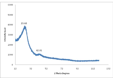
The X-ray diffraction (XRD) pattern of diesel soot is shown in figure 4. The carbonaceous soot obtained was used directly. The Bragg diffraction peaks at 2θ = 23.68o and 42.01o are the only peaks obtained in the X-ray diffraction analysis. These two intense peaks correspond to hexagonal graphite lattice of multi-walled carbon nanotubes [20,21]. The peaks at 2θ = 23.68o is a moderately high intensity broad peak which indicates the presence of large amounts of amorphous material in association with nanotubes. The low intensity of the peak at 2θ = 42.01o, is an indication of the low quality of carbon nanomaterial present in the soot.
[image:6.596.68.527.125.445.2]
individual particles. Since no catalyst was used in the production of nanomaterials from the diesel, catalyst particle are absent from this HR-TEM micrograph.
Figure 4. X-ray diffraction spectra of soot obtained from the atmospheric combustion of diesel.
Morphological details indicate the nanomaterials obtained from the atmospheric combustion of diesel as nanospheres, observed in the Raman spectral analysis, is further corroborated in the HR-TEM micrograph [22].
[image:7.596.118.481.79.267.2]
(C) (D)
Figure 5. HR-TEM micrograph of soot obtained from the atmospheric combustion of diesel.
Figure 6. Thermogravimetric analysis graph of soot obtained from the atmospheric combustion of diesel fuel.
[image:7.596.71.525.321.628.2]
The HR-TEM micrograph, figure 5 (c & d) reveal lattice fringe images of graphene layers of individual nanospheres. The crystalline presentation of the layers reflects the graphitization of the nanospheres.
TG analysis was employed to examine the thermal stability of the diesel fuel soot. The temperature at which oxidized occurs is an index of the stability of carbonaceous soot obtained from nanomaterials. Thermogravimetric analysis (TGA) of diesel fuel soot is presented in figure 6. The thermogravimetric curve obtained indicates a gradual and continual weight loss in the diesel fuel soot from 50oC to about 900oC. The curve does not produce any endothermic weight loss plateau which is indication of the absence of decomposition products from the diesel fuel soot. From an initial mass of 2.487 mg of diesel fuel soot, a weight loss of only 78.41% was obtained after heating for approximately 900oC.
4. CONCLUSION
Carbonaceous soot produced from diesel without a catalyst precursor show the presence of significant amount of carbon nanomaterial. The HR-TEM micrographs provide a clear indication that these nanoparticles are carbon nanospheres. Raman spectroscopy and X-ray diffraction investigation shows the presence of carbon nanotubes in association with amorphous nanomaterial due to the presence of the D and G bands found in carbon nanotubes. EDS analysis of diesel soot provide strong evidence of soot particles to be composed of primarily carbon and oxygen. The presence of a peak corresponding to sulphur is recorded in the EDS analysis.
ACKNOWLEDGEMENT
This work was supported by a research grant from the Faculty of Applied and Computer Science Research and Publications Committee of Vaal University of Technology, Vanderbijlpark.
References
1. D.W.E.A. Santana, M.P. Sepulveda, P.J.S. Barbiera, J. Fuel, 86 (2007) 911. 2. M. Al-Ghouti, Y. Al-Degs, F. Mustafa, J. Fuel, 89, (2009) 193
3. W. Jambers, L. De Bock, R. Van Grieken, J. Anal. Chem., 355, (1996) 521 4. R.Kaegi, L. Holzer, J. Atm. Environ, 37, (2003) 4353
5. M. Kumar, P.D. Kichambare, M. Sharon, Y. Ando, X. Zhao, Mater. Res. Bull., 34(5), (1999) 791 6. E.D. Dikio, F.T. Thema, C.W. Dikio, F.M. Mtunzi, Int. J. Nanotech. Appl., 4(2), (2010) 117 7. E.D. Dikio, N. Bixa, Int. J. Appl. Chem. 7(1), (2011) 35,
8. J.T. Han, J.H. Woo, H.S. Kim, J.G. Jee, Bull. Korean Chem. Soc., 24(12), (2003) 1771
9. P. Benito, M. Herrero, F.M. Labajos, V. Rives, C. Royo, N. Latorre, A. Monzon, Chem. Eng. J., 149, (2009) 455
10.J. Liu, M. Shao, X. Chen, W. Yu, X. Liu, Y. Qian, J. Am. Chem. Soc. 125(27), (2003) 8088 11.M. Shao, Q. Li, J. Wu, B. Xie, S. Zhang, Y. Q, Carbon. 40, (2000) 2961
13.A.Nieto-Marquez, D. Toledano, P. Sanchez, A. Romero, J.L. Valverde, J. Catal., 269, (2010) 242 14.M. Bystrzejewski, H. Lange, A. Huczko, P. Baranowski, H.W. Hubers, T. Gemming, T. Pichler, B.
Buchner, M.H. Rummeli, J. S. S. Chem. 181, (2008) 2796
15.V.O. Nyamori, S.D. Mhlanga, N.J. Coville, J. Organomet. Chem., 693, (2008) 2205 16.H. Burtscher, J. Aero Sci. 36, (2005) 896
17.L.A. Dombrovsky, S.S. Sazhin, S.V. Mikhalovsky, R. Wood, M.R. Heikal, J. Fuel, 82 (2003) 15. 18.S.K. Srivastava, V.D. Vankar, V. Kumar, J. Thin Solid Films, 515, (2006) 1552
19.A.Eftekhari, P. Jafarkhani, F.Moztarzadeh, Carbon., 44, (2006) 1343
20.R.M. Malek Abbaslou, J. Soltan, A.K. Dalai, Appl. Catal. A: Gen., 379, (2010) 129 21.H. Mi, X. Zhang, Y. Xu, F. Xiao, Appl. Surf. Sci., 256, (2010) 2284
22.S. Ndwandwe, P. Tshibangu, E.D. Dikio, Int. J. Electrochem. Sci. 6, (2011) 749