Int. J. Electrochem. Sci., 6 (2011) 2767 - 2788
International Journal of
ELECTROCHEMICAL
SCIENCE
www.electrochemsci.org
Electrochemical Polarization Behaviour of Electroless Ni-P
Deposits with Different Chromium-Free Pre-Treatment on
Magnesium Alloy
Jothi Sudagar, Guangli Bi, Zhonghao Jiang, Guangyu Li, Qing Jiang, Jianshe Lian*
The Key Lab of Automobile Materials, Ministry of Education, College of Materials Science and Engineering, Nanling campus, Jilin University, Changchun 130025, China
*
E-mail: [email protected]
Received: 5 May 2011 / Accepted: 7 June 2011 / Published: 1 July 2011
Different chromium-free conversion coatings such as phosphate-manganese-molybdate, vanadium and tannic-acid were used as pre-treatment for the electroless NiP deposition on magnesium alloy. The corrosion effects of NiP deposits with these pre-treatment were analyzed by electrochemical polarization tests. This revealed that NiP with tannic-based pre-treatment increased the corrosion resistance. SEM and EDS analysis revealed that it influenced not only the morphology, but also the phosphorus content of the NiP deposit. The marginal increase in phosphorus forms a layer of adsorbed hypophosphite anions, thereby preventing the hydration of nickel and forming a passive film. Furthermore, it smoothens (AFM) the NiP deposit was also the reason for the influence.
Keywords: Magnesium alloy, electroless Ni-P deposits, polarization, passive films.
1. INTRODUCTION
Magnesium and its alloys play an important role in many fields such as aerospace, electronics and automobile fields; owing to their unique characteristics of higher strength-to-weight ratio. They also have the advantages of high specific strength modulus and excellent anti-shock resistance. Therefore, they are inevitable for aerospace and automotive industries and also in manufacturing electrical equipment such as cellular phones, television sets, and sporting industries [1].
Because of their heat conductivity and electromagnetic shielding effectiveness they are also attractive features for information technology industry and for communication satellites [2]. However, it has poor atmospheric corrosion resistance and very reactive in the air, which means the magnesium oxide film will be corroded easily.
aqueous solutions. Hence, it is not suitable to be used without any protective layer, especially in a humid environment. Furthermore, it is necessary to do surface treatment properly onto the surface to improve the adhesion, wear and corrosion resistance [3, 4].
In recent decade, different surface treatment techniques have been applied for the protection of magnesium alloys, which include conversion treatment, electroplating/electroless and anodic treatment. Conversion coatings are produced by chemical or electrochemical treatment of a metal surfaceto make a superficial layer of substrate metal oxides, chromates, phosphates, or other compounds that are chemically bonded to the surface [5]. There are different types of conversion coatings including chromate, phosphate/permanganate [6, 7], stannate-based [8], cerium-based, lanthanum and praseodymium conversion coatings [9, 10, 11], tannic-based coatings [12] and organic-based (silane) coatings [13].
Conversion coating is an important coating technique for magnesium alloys to resist the corrosion. Conversion coatings alone can not provide resistance from harsh corrosion, but can provide a good base for producing adherent organic coatings or paints or metallic coatings. Metallic coatings are needed for better surface finish (corrosion and wear) on magnesium alloy. Electroplating or electroless is one of the most cost effective and simple techniques for depositing a metallic coating to the magnesium substrate. In both cases, a metal salt in solution is reduced to its metallic form on the surface of the work piece.
Electroless deposition is much suitable method to deposit metal-metalloid alloy coatings than electroplating, involving the deposition with uniform, crack-free and good adhesion onto magnesium alloy, without applying an external electrical circuit. The most difficult process of plating magnesium is developing a suitable pre-treatment part. If the suitable pre-treatment is in placed, many desired metals can be plated. Conventionally, the magnesium alloy was etched in a solution of chromium oxide plus nitric acid and soaked in HF solution to form a conversion film (MgF ) before electroless 2 plating. Due to high toxicity on environment, the hexavalent chromium compounds are restricted and HF also exhibits strong corrosive nature.
2. EXPERIMENTAL PROCEDURE
[image:3.596.114.493.459.601.2]The substrate material used was AZ91D die cast magnesium alloy with a size of 15×15×5 mm. The alloy was mainly contained about 9.1 wt. % Al, 0.64 wt. % Zn, 0.17 wt. % Mn, 0.001 wt. % Fe and Mg balance. The substrate was ground with No. 2000 SiC paper.
Table 1. The operating parameters of alkaline cleaning on the AZ91D magnesium alloy.
Process Parameters Conditions
Grinding Up to No. 2000 SiC sandpaper Alkaline
cleaning
NaOH - 45 g/L 3 4. 2
Na PO .12H O - 10 g/L
338 K, 20 min
After grinding, the sample was rinsed with deionized water, cleaned in acetone ultrasonically for a while and finally dried, before take into the degreasing process. After degreasing (given in Table-1), the above-mentioned chromium-free pre-treatments were applied before the electroless NiP plating. Magnesium and its alloys have a high affinity to oxygen, which means that the freshly cleaned samples will always be covered with a thin oxide film growing rapidly. So, samples should be transferred as quickly as possible between any two procedures.
Table 2. Pre-treating bath for Phosphate-manganese-molybdate pre-coating for AZ91D alloy.
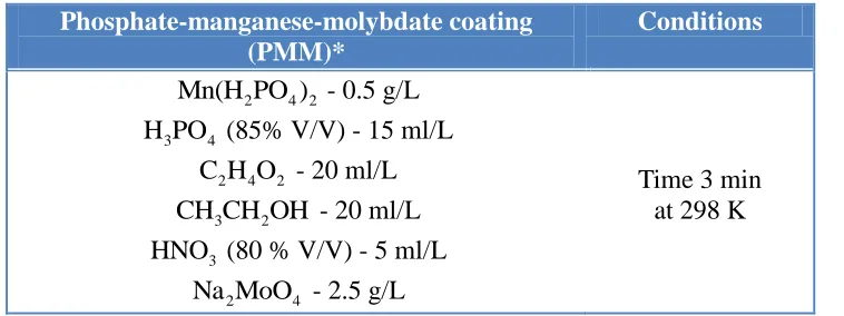
Phosphate-manganese-molybdate coating (PMM)*
Conditions
2 4 2
Mn(H PO ) - 0.5 g/L 3 4
H PO (85% V/V) - 15 ml/L 2 4 2
C H O - 20 ml/L 3 2
CH CH OH - 20 ml/L 3
HNO (80 % V/V) - 5 ml/L
2 4
Na MoO - 2.5 g/L
Time 3 min at 298 K
*Phosphate-manganese-molybdate coated pre-treatment sample is represented by AZ91D/PMMC
The phosphate-manganese-molybdate coating (PMMC) (given in Table-2) is a modification of the common phosphate-manganese pre-treatment procedure. Because, the addition of molybdenum from sodium molybdenum can disintegrate into MoO2-4 ions, which could combines with metal ions to formMgMoO4as follows.
(1) (2)
+
2-2 4 4
2+
2-4 4
Na MoO 2Na +MoO
Mg +MoO MgMoO
And then, this behave as the cathode sites (in similar with magnesium matrix) and stimulate the phosphates-manganese conversion coating [14]. This is similar to the case of phosphating on steel,
where
2-4
MoO ions coupled with 2
Fe to form FeMoO that is absorbed onto the iron substrate to 4 behave as nuclei to stimulate the growth of phosphates [15]. Hence, the addition of molybdate could create more suitable cathode sites for the facilitating and growth of phosphate film. As a consequence, a fine and fully covered phosphate film was formed on the substrate.
Table 3. Pre-treating bath for Vanadium pre-coating for AZ91D alloy.
Vanadium based coating pre-treatment (VBC)* Conditions
3
NaVO - 30 g/L Time 15 min
[image:4.596.116.475.343.485.2]at 353 K. pH 8.0. *Vanadium based coating pre-treatment sample is represented by AZ91D/VBC.
Table 4. Pre-treating bath for Tannic acid based pre-coating for AZ91D alloy.
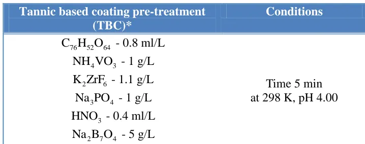
Tannic based coating pre-treatment (TBC)*
Conditions
76 52 64
C H O - 0.8 ml/L 4 3
NH VO - 1 g/L 2 6
K ZrF - 1.1 g/L 3 4
Na PO - 1 g/L 3
HNO - 0.4 ml/L 2 7 4
Na B O - 5 g/L
Time 5 min at 298 K, pH 4.00
*Tannic based coating pre-treatment sample is represented by AZ91D/TBC.
Another pre-treatment technique applied is vanadium based coating (VBC) (given in Table-3). Vanadium conversion is generally used as the corrosion resistant inhibitor for the paint or pigment system, it is scanty to be used on magnesium alloy. The vanadium coating formation process is gelatine of hydrated vanadium oxide, which is softer than those by other methods, and easy to control. The formation of pentavalent vanadium oxides by condensation and polymerization has been responsible for the formation. Vanadium oxide gel formation includes ovation of octahedrally coordinatedVO(OH) (OH ) . Yang et.al had developed the vanadium based conversion coating on the 3 2 2 AZ61 magnesium alloy and reported that corrosion resistance of vanadium coating is better than cerium and phosphate coatings, and in addition this vanadium chemical conversion treatment has potential to replace the chromium-based conversion coating treatment [16]. The vanadium treatment of 10 min time was good for AZ61 alloy and 15-20 min time was good for AZ91D case. The increasing β-phases in this AZ91D case might be the reason for the delay in the coating time [17].
[image:5.596.108.539.245.396.2]
through a solution containing C H O (tannic acid),76 52 46 NH VO , K ZrF and4 3 2 6 H PO . Pentahydroxy 3 4 benzamide-magnesium complex was the main component of the coating, which is succeeding in two steps: Zr(HPO ) .H O(α-ZrP) formed first at ~70 to 120 second of immersion time, which behaved as 4 2 2 a catalyst to activate the main reaction. The oxidization of gallic acid into pentahydroxy benzoic acid was the second reaction, as well as the formation of pentahydroxy benzamide-magnesium complex, which took place in the time interval of about 120 to 300 s. The reactions take up first on β phases and then spread to α phase [12].
Table 5. Bath composition and operating parameters of electroless NiP deposits.
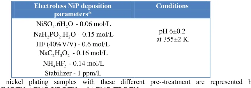
Electroless NiP deposition parameters*
Conditions
4 2
NiSO .6H O - 0.06 mol/L 2 2 2
NaH PO .H O - 0.15 mol/L HF (40%V/V) - 0.6 mol/L
2 3 2
NaC H O - 0.16 mol/L 4 2
NH HF - 0.14 mol/L Stabilizer - 1 ppm/L
pH 6±0.2 at 355±2 K.
*Electroless nickel plating samples with these different pre--treatment are represented by AZ91D/PMMC/EN, AZ91D/VBC/EN and AZ91D/TBC/EN.
After being pretreated in the above pre-treatment baths separately, the samples were immersed in the electroless bath solution for NiP deposition layer. The technical flow chart of the electroless NiP deposition is shown in Table-5. The samples were cleaned thoroughly with de-ionized water as soon as possible between any two steps of the treatments. The electroless solution was put in a 1000 ml glass beaker, which was kept at constant temperature by a thermostat. The bath composition and all the operation parameters for the electroless NiP deposition are listed in Table-5. The thickness of Ni-P deposition was calculated by weight gain method and it was found to be around 25 µm.
The structures were studied by the X-ray diffractometer (XRD, Rigaku Dymax) with a Cu Kα radiation (γ=0.154178 nm) and a monochromator at 50 kV and 300 mA with the scanning rate and step being 4°/min and 0.02°, respectively. X-ray photoemission spectroscopy (XPS) was used to analyze the component of the conversion coatings prior to electroless NiP depositions. XPS spectra of the coatings were acquired with an ESCALABMk II (Vacuum Generators) spectrometer using un-monochromatized Al Ka X-rays (240 W). Cycles of XPS measurements were done at high vacuum chamber with a base pressure of 10 Torr. The surface morphology of the electroless nickel coatings -8 were observed by using scanning electron microscope (SEM, JEOL JSM-5310) and an EDS attachment was used for qualitative elemental chemical analysis. The surface topography of the electroless coated samples was observed by atomic force microscope (AFM) and their histogram reveals the surface roughness (R ) value of the electroless NiP samples. a
(Versa STAT-3, METEK, Princeton Applied Research), which was controlled and supported by a computer software system.
Polarization (Potentiodynamic, Tafel and linear) experiments were conducted at ambient temperature (~25ºC). The experiments were carried out in a 3.5 wt. % NaCl aqueous solution using a three-electrode cell with a platinum plate (Pt) as counter electrode and a saturated calomel electrode (SCE, +242 mV vs. SHE) was fitted through the rubber stopper and used as a reference electrode. The exposed area for testing was obtained by thick coating the sample with epoxy resin leaving an uncovered area of 1 cm². The reference and platinum electrodes were fixed near to the working electrode (~0.5 mm), which could minimize the errors due to IR drop in the electrolytes. All the experiments were performed with the scan rate of 5 mV/s. The log (i)–E curves were measured and plotted after the above electrochemical measurements. The free corrosion potential was stabilized prior to each potentiodynamic and anodic polarization experiment. However, the Tafel experiments were conducted immediately on immersion of the sample in the electrolyte in order to understand the corrosion resistance of fresh surfaces of EN deposits on magnesium alloy and also avoid passivation to measure the corrosion rate.
3. RESULTS AND DISCUSSION
3.1. The study of chromium-free treatments on AZ91D Mg alloy
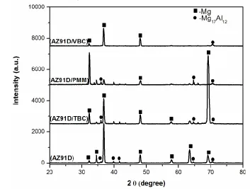
[image:6.596.114.467.442.709.2]The XRD patterns of the AZ91D magnesium alloy substrate, the three different chromium-free pre-treated surfaces are shown in Fig.1.
[image:10.596.96.500.71.728.2]
Conversion coating thickness is less than 1 µm,hence, the phases in the pretreatment layer detected very less by XRD; the pale colored surface may imply the existence of passive film on the substance. At the same time, the AZ91D magnesium alloy consisted of primary α-Mg phase surrounded by a eutectic mixture of α and β-Mg Al [18]. There is an internal galvanic corrosion 17 12 caused by the second phases or impurities. The β-phase precipitated along the grain boundaries, which exhibited higher cathodic reaction activity and lower corrosion current density than that of α [18]. Hence, a suitable pre-treatment is in need to make sure for the successful metallic coating on magnesium alloy. After pre-treatment, α phase was slightly eroded and β phase was exposed on the surface. This results in the increase of the volume fraction of β phase on the surface. Both the precipitation of conversion coatings and the increase of the volume fraction of β phase can improve the corrosion resistance of the substrate, because the galvanic corrosion is reduced [19].
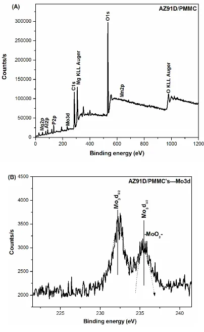
The XPS was used to analyze the component of the conversion coatings prior to electroless NiP deposits.The spectra of the different chromium-free pre-treated samples were shown in Figs. 2-4, respectively. XPS spectrum of Mg2p, Al2p, C1s and O1s peaks are commonly seen in all the three pre-treated samples. Fig. 2(A) shows the XPS spectrum of tannic based coating on AZ91D substrate (AZ91D/TBC). Both the P2p peak (Fig. 2(B)) at 133.44 eV and the Zr3d5/2 peak at 182.9 eV are assigned to α-ZrP [20]. However, these both peaks will form only in the early stage of conversion coating, which may act as catalyst to facilitate the subsequent reaction of gallic acid oxidation into pentahydroxy benzoic acid. The C1s spectrum (Fig. 2(C)) reveals three peak structures with binding energies at 284.5 eV, 285.85 eV and 288.01 eV respectively. The peak at 284.5 eV is caused by pollution during XPS measurement. The peak at 285.85 eV is attributed to -C H -C(O)- group in the 6 4 organic polymer [21], which should be the reaction product of tannic acid. The N1s peak (Fig. 2(D)) locates at 399 eV assigned to the -H N-C(O)- group [22]. The Mg2p peaks at 49.6 eV and 51.0 eV are 2 observed, which are attributed to the Mg-Mg bond [23] and Mg-F bond [24], respectively. Fig. 2(A) also shows the peaks of O1s, Mg2p and F1s obtained on sample treated for TBC. Mg2p and F1s peaks are attributed to substrate Mg and fluoride in the conversion coating, respectively. Fig. 3(A) shows the XPS spectrum of vanadium based coating on AZ91D substrate (AZ91D/VBC). The V2p peak (Fig. 3(B)) reveals three peak structures with binding energies at 512 eV, 516.65 eV and 524.3 eV respectively. The peak at 512 eV is attributed to -V-metallic vanadium bond [25]. The peak at 516.65 eV and 524.3 eV are attributed to -V O - group in the metallic oxide form [26]. The Al2p peak reveals 2 5 that Al V bonds are present in the 88.5 eV range. Fig. 4(A) shows the XPS spectrum of phosphate-3 manganese-molybdate coating on AZ91D substrate (AZ91D/PMMC). Apart from the Mg2p, Al2p P2p, C1s and Mn2p peaks, the Mo3d peak is important in this PMMC pre-treatment and it (Fig. 4(B)) reveals two-peak structures with binding energies at 232.9 eV and 235.3 eV. The both peaks are attributed to -MoO - group in the metallic oxide form [26]. The Mn2p peak is also present at 642.12 3 eV range.
increase of the volume fraction of β phase can improve the corrosion resistance of the substrate, during electroless NiP deposit. The effect of electrochemical polarization (potentiodynamic, anodic and tafel) results on these three chromium-free pretreatment layers for electroless process is discussed in coming section.
3.2. The electrochemical properties of electroless NiP with different pre-treatments
The three different chromium-free treatments were successfully used as a pre-treatment for electroless NiP alloy coating on the AZ91D Mg alloy substrate. The XRD pattern of the electroless NiP deposit with different pre-treatment on AZ91D alloy is shown in Fig. 5.
Figure 5. XRD patterns of EN deposit with three different chromium-free pre-treated on AZ91D alloy.
[image:12.596.75.520.265.536.2]
content by EDS analysis (not shown) reveals that all three samples are in the medium range (~5.8 wt. %) of the mixture of nanocrystalline and amorphous structure [30]. But there was a relatively high ‘P’-content for the sample AZ91D/TBC/EN than other cases. It is generally accepted that the relative ratio of nanocrystalline and amorphous or a co-existence of these two phases depends on the phosphorus content [30].
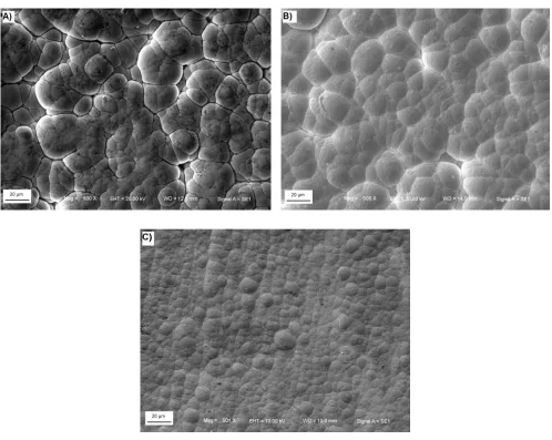
The surface morphology of electroless NiP deposits with different pre-treatments is shown in Fig. 6 (A, B & C).
Figure 6. SEM images of EN deposit with: (A) Phosphate-manganese-molybdate coating, (B) Vanadium based coating, (C) Tannic based coating on AZ91D alloy.
[image:13.596.50.548.210.607.2]
deposition, but also on the whole catalytic EN deposition process. Thus, it is believed that by changing the surface structure and size of active area of substrate, it can influence the nucleation rate of electroless NiP at the initial stage. In addition, the lateral joining of the growing crystallites can also be evidently influenced. Hence, not only the morphology, but also the micro porosity and other in-homogeneities (e.g. degree of internal stress and type) of the EN deposition will be influenced as well.
Figure 7. Potentiodynamic polarization curves of different chromium-free pre-treated EN deposit on AZ91D magnesium alloy. The experiments were conducted after stabilization of free corrosion potentials (conducted at room temperature in 3.5 wt% NaCl at a scan rate of 5 mV/s).
[image:14.596.94.502.185.511.2]
polarization curve the passivation parameters, i.e., zero current potential (ZCP), potential for primary passivation (Epp), potential for complete passivation (Ecp ), critical current density (icrit), passive current density (ipass), passive range (E -Eb cp) and break-down potential (Eb) are presented in Table-6.
Table 6. Passivation parameters obtained from polarization curves of different chromium-free pre-treated EN on AZ91D alloy in 3.5 wt. % NaCl at room temperature.
Passivation
parameters AZ91D/VBC/EN AZ91D/PMMC/EN AZ91D/TBC/EN
ZCP (mV vs. SCE)
pp
E (mV vs. SCE)
cp
E (mV vs. SCE) b
E (mV vs. SCE)
b cp
E -E (mV) crit
i (μA/cm²)
pass
i (μA/cm²)
-731 -676 -583 -241 342 30.4 110.6 -714 -669 -590 -213 377 26.1 118.9 -618 -577 -515 -107 408 20.4 45.2
[image:15.596.86.513.306.713.2]
The critical current densities and passive current densities were determined at EppandEcp, respectively. In specific, there was a shift in ZCP towards positive direction for AZ91D/TBC/EN compare to those with PMMC and VBC. The positive shift in the ZCP may be attributed to changes in hydrogen reduction processes [31], due to substantial fraction of atoms lie in the inter-crystalline region of nano crystalline nickel. The critical current densities of passivation for all the samples were approximately similar. This indicates that the mechanism of onset of passivity and passivation itself is similar in nature for all the case.
[image:16.596.106.494.443.712.2]There was a noticeable change in the passive range for TBC compared to other cases. There was a significant change in the passive current density for TBC compared to PMMC and VBC. This might be non-defective nature of passive film formed on TBC. The reason may be related to the relatively high (than VBC and PMMC) phosphorus content on the surface reacts with water to form a layer of adsorbed hypophosphite anions. Hence, the passive film formed by TBC passive film has positive influence [28]. When the applied anodic potential was high enough to breakdown the passive film, pitting corrosion occur at the grain boundaries. Fig. 8 shows anodic polarization curves recorded of the EN deposited magnesium alloy with different pre-coatings in 3.5 wt. % NaCl solution at room temperature. The experiments were conducted after stabilization of free corrosion potentials. As the anodic potential increases towards positive direction, the corrosion current started to increase slowly. The current plateau is clearly associated with the metallic oxidation. The dissolution of metal matrix differs marginal for EN deposited with TBC. This behavior indicates similar like that of the marginal increase in the potentiodynamic polarization test also.
Fig. 9 shows Tafel curves recorded in 3.5 wt% NaCl solution for the EN deposited magnesium alloy with different pre-coatings at room temperature. Linear Tafel regions were obtained for Tafel experiments conducted immediately after immersion of the sample in the electrolyte and also freshly prepared samples were used to avoid passivation. However, establishing linear Tafel regions, especially in the anodic portion of the polarization curves (for AZ91D/TBC/EN) was difficult (Fig. 9). Often experimental curves do not display the expected log/linear Tafel behaviour with both anodic and cathodic branches exhibiting curvature [32]. Harvey and Paul developed a non-commercial computer program (SYMADEC) for the interpretation of polarization curves for the Fe/H O/H /O corrosion 2 + 2 system. The SYMADEC allows for the insertion of different values of film resistance and subsequent calculation of corrosion rate from the polarization curves not exhibiting a Tafel region [32, 33]. The Tafel slopes aand c were estimated from the polarization curves. Least values of a and c lead to least corrosion rate according to the Stern-Geary relation [34].
2.303 ( )
a c corr
p a c i
R
(3)
where, icorris the corrosion current density and Rpis the polarization resistance. And corrosion rates conversion were calculated by the following equation.
2 3.28M
1(mA/cm ) = ( ) mm/y
nd (4)
where, M is atomic mass, n is number of electrons freed by the corrosion reaction and d is the density. For nickel, 2
1(mA/cm ) = 10.93 mm/y . However, the nickel is associated with phosphorous content in this electroless NiP deposit, so the value gives approximation only.
Table 7. Results of Tafel extrapolation experiment conducted in 3.5 wt. % NaCl at a scan rate of 5 mV/s. The experiment was conducted immediately after immersion of the samples in the electrolyte.
Sample c a icorr(Tafel extrapolation) Rp(Ω cm²) (V/decade) μA/cm² mm/y
AZ91D/VBC/EN AZ91D/PMMC/EN
-0.155 0.199 -0.1467 0.1676
103.87 1.135
88.07 0.9626
2929 5800
[image:17.596.73.524.586.680.2]
However, AZ91D/TBC/EN curve not exhibited the expected linear Tafel behaviour in cathodic curvature region to find out the corrosion rate.
Figure 10. Schematic models for chemical passivation of EN deposits with different chromium-free conversion coatings during corrosion at room temperature in 3.5 wt% NaCl solution.
[image:18.596.141.499.135.663.2]
Figure 11. AFM images of EN deposits with: (A) Phosphate-manganese-molybdate; (B) Vanadium based coating; (C) Tannic based coating, on AZ91D alloy.
The schematic diagram (in Fig. 10) illustrated (why TBC/EN had passivation); the general preferential dissolution of nickel produces a P-rich chemically passive layer which hinders further dissolution of nickel in TBC case. The amorphous electroless NiP deposits passivate in acidic and neutral solution, but the presence of crystalline structures increased corrosion rates dramatically [35] and therefore, the present case had good agreement with this. All smooth surfaces possess some degree of roughness, even if only at the atomic level.
Correct function of the fabricated component often is critically dependent on its degree of roughness [36]. The AFM images of electroless NiP deposits with different pre-treatment were presented in Fig. 11 (A, B & C). Fig. 11 (A) & (B) shows surface topography of electroless NiP deposits with VBC and PMMC. The Ni particle deposited on the substrate surface gives rise to peaks and valleys. The average R value is about 3.053 and 2.986 µm for VBC and PMMC, respectively. Fig. a 11 (C) shows the surface topography of EN deposits with TBC. The Ni deposited on the substrate surface is more and uniform. The AFM image of EN with TBC appears to be relatively smooth and the
a
R value is 1.477 µm.
[image:20.596.92.521.81.391.2]
more irregular. This also can be evident for the increase in corrosion resistance of TBC pre-treated EN than others and the electrochemical measurement analyses conclude the same.
4. CONCLUSIONS
In this study, the effects of chromium-free pre-treatments on the corrosion properties of electroless NiP deposit were investigated by electrochemical polarization measurements. The main conclusions of this research investigation are:
1. The XPS study reveals the phases of the chromium-free coatings on AZ91D alloy. SEM and EDS reveal that the different chromium-free pre-treatment influencing not only the morphology, but also changed the type (‘P’ content) of the EN deposits as well. This marginal increase in phosphorus (AZ91D/TBC/EN) forms a layer of adsorbed hypophosphite anions, thereby preventing the hydration of nickel and forming a passive film.
2. All the pre-treated electroless NiP samples exhibited active-passive polarization behaviour. The shift of zero current potential towards positive direction with ascending order (VBC<PMMC<TBC) has been related to modification in cathodic reaction (hydrogen reduction) processes. The passive current densities for TBC/EN were lower than that of other cases and this has been related to the non-defective nature of passive film formed on TBC/EN. The breakdown potential for all electroless NiP was more or less similar in nature. From the Tafel plots, the corrosion resistance was good for TBC/EN compare to other pre-treated electroless NiP deposits.
3. The AFM result shows that the atomic level smoothness was found in the TBC/EN. Metal cations are more readily dissolved from surface irregularities (surface roughness) than a flat face. This was the evident reason for the marginal increase in corrosion resistance of TBC/EN than other pre-treated in this study.
ACKNOWLEDGEMENTS
This work was supported by National Nature Science Foundation (Grant No. 50871046), the Foundation of National Key Basic Research and Development Program (No.2010CB631001) and the Program for Changjiang Scholars and Innovative Research Team in University. One of our authors (J. Sudagar) acknowledges to Indo-China cultural exchange scholarship program by the Ministry of Human Resource Department (MHRD, India) and Ministry of Education (MOE, China).
References
1. B. Landkof, in: K.U. Kainer (Ed.), Proc. Magnesium Alloys and their Applications, Wiley-VCH Verlag, Weinheim, (2000) 168.
2. A.K. Sharma, M.R. Suresh, H. Bhojraj, H. Narayanamurthy, S.P. Sahu, Met. Finish. (1998) 10. 3. G.O. Mallory, J.B. Hajdu (Eds.), Electroless Plating: Fundamentals and Applications, AESF
Publishing, Orlando, FL, (1991) 261.
5. F.A. Lowenheim, Modern Electroplating, Wiley, New York, (1974) 81. 6. H. Umehara, M. Takaya, S. Terauchi, Surf. Coat. Technol. 169 (2003) 666. 7. K.Z. Chong, T.S. Shih, Mater. Chem. Phys. 80 (2003) 191.
8. M.A. Gonzalez-Nunez, P. Skeldon, G.E. Thompson, H. Karimzadeh, P.Lyon, T.E. Wilks, Corros. Sci. 37 (1995) 1763.
9. R.G. Buchheit, S.B. Mamidipally, P. Schmutz, H.Guan, Corrosion. 58 (2002) 3.
10.Katya Brunelli, Manuele Dabala, Irene Calliari, Maurizio Magrini, Corros. Sci. 47 (2005) 989. 11.L. Rudd, C.B. Breslin, F. Mansfeld, Corros. Sci. 42 (2000) 275.
12.Xiaoming Chen, Guangyu Li, Jianshe Lian, Qing Jiang, Surf. Coat. Technol. 204 (2009) 736. 13.H.J. Kim, J. Zhang, R.H. Yoon, R. Gandour, Surf. Coat. Tech. 188 (2004) 762.
14.J.S. Lian, G.Y. Li, L.Y. Niu, C.D. Gu, Z.H. Jiang, Q. Jiang, Surf. Coat. Technol. 200 (2006) 5956. 15.G.Y. Li, J.S. Lian, L.Y. Niu, Z.H. Jiang, ISIJ Int. 45 (9) (2005) 1326.
16.K.H. Yang, M.D. Ger, W.H. Hwu, Y. Sung, Y.C. Liu, Mater. Chem. Phys. 101 (2007) 480. 17.J. Sudagar, Y.Q. Liang, G.Y. Li, Q. Jiang, J. S. Lian, Mater. Chem. Phys. (submitted). 18.G. L. Song, A. Atrens, M. Dargusch, Corros. Sci. 41 (1998) 249.
19.G. L. Song and A. Atrens, Adv. Eng Mater. 1 (1999) 11.
20.G. Mattogno, C. Ferragina, M.A. Massucci, P. Patrono, A. La Ginestra, J. Electron Spectrosc. Relat. Phemon. 46 (1988) 285.
21.D.T. Clark, W.J. Feast, P.J. Tweedale, H.R. Thomas, J. Polym. Sci: Polym. Chem. Ed. 18 (1980) 1651.
22.T. Yoshida, K. Yamasaki, S. Sawada, Bull. Chem. Soc. Jpn. 51 (1978) 1561. 23.C.D. Wagner, J.Electron Spectrosc. Relat. Phenom. 18 (1980) 345.
24.R. Hoogewijs, L. Fiermans, J. Vennik, J. Electron Spectrosc. Relat. Phenom. 11 (1977) 171. 25.C. Malitesta, G. Razzini, L. Peraldo bicelli, L. Sabbatini, Int. J. Hydrogen Energy. 12 (1987) 219. 26.D. Borgmann, E. Hums, G. Hopfengartner, G. Wedler, G.W. Spitznagel, I. Rademacher, J.
Electron Spectrosc. Relat. Phenom. 63 (1993) 91.
27.Liping Wang, Junyan Zhang, Yan Gao, Qunji Xue, Litian Hu, Tao Xu, Scripta Mater. 55 (2006) 657.
28.P.H. Lo, W.T. Tsai, J.T. Lee, M.P. Hung, Surf. Coat. Technol. 67 (1994) 17.
29.T.S.N. Sankara Narayanana, I. Baskaranb, K. Krishnavenia, S. Parthiban, Surf. Coat. Technol. 200 (2006) 3438.
30.Z. Guo, K.G. Keong, W. Sha, J. Alloys Compd. 358 (2003) 112.
31.Woo-Jae Cheong, Ben L. Luan, David W. Shoesmith, Corros. Sci. 49 (2007) 1777. 32.Harvey J. Flitt, D. Paul Schweinsberg, Corros. Sci. 47 (2005) 3034.
33.H.J. Flitt, D.P. Schweinsberg, Corros. Sci. 47 (2005) 2125. 34.M. Stern, A.L. Geary, J. Electrochem. Soc. 104 (1957) 56.
35.A.Krolikowski, B. Pokrywa, Electrochem. Acta. 38 (1993) 1979.
36.R. Elansezhian, B. Ramamoorthy, P. Kesavan Nair, J. Mater. Process Tech. 209 (2009) 233.