This is a repository copy of The impact of realistic casing geometries and clearances on
fan blade tip aerodynamics.
White Rose Research Online URL for this paper:
http://eprints.whiterose.ac.uk/135158/
Version: Accepted Version
Article:
John, A., Qin, N. orcid.org/0000-0002-6437-9027 and Shahpar, S. (2018) The impact of
realistic casing geometries and clearances on fan blade tip aerodynamics. Journal of
Turbomachinery, 140 (6). 061002. ISSN 0889-504X
https://doi.org/10.1115/1.4038834
© 2018 Rolls-Royce plc / ASME. This is an author produced version of a paper
subsequently published in Journal of Turbomachinery. Uploaded in accordance with the
publisher's self-archiving policy, under the terms of the Creative Commons Attribution
Licence (http://creativecommons.org/licenses/by/4.0)
eprints@whiterose.ac.uk
Reuse
This article is distributed under the terms of the Creative Commons Attribution (CC BY) licence. This licence allows you to distribute, remix, tweak, and build upon the work, even commercially, as long as you credit the authors for the original work. More information and the full terms of the licence here:
https://creativecommons.org/licenses/
Takedown
If you consider content in White Rose Research Online to be in breach of UK law, please notify us by
Proceedings of ASME Turbo Expo 2017: Turbomachinery Technical Conference and Exposition GT2017 June 26 - 30, 2017, Charlotte, USA
GT2017-64403
FAN BLADE TIP AERODYNAMICS WITH REALISTIC OPERATIONAL CASING
GEOMETRIES AND CLEARANCES
Alistair John University of Sheffield
Sheffield, S1 3JD United Kingdom adjohn1@sheffield.ac.uk
Ning Qin University of Sheffield
Sheffield, S1 3JD United Kingdom
Shahrokh Shahpar Rolls-Royce Derby, DE24 8BJ
United Kingdom
ABSTRACT
During engine operation fan casing abradable liners are worn by the blade tip, resulting in the formation of trenches. This paper investigates the influence of these trenches on the fan blade tip aerodynamics. A detailed understanding of the tip flow fea-tures for the fan blade under investigation is developed. A para-metric model is then used to model trenches in the casing above the blade tip. It is shown that increasing clearance via a trench reduces performance by less than increasing clearance through cropping the blade tip. A response surface method is then used to generate a model that can predict fan efficiency for a given set of clearance and trench parameters. It is shown that the efficiency sensitivity to clearance is greater for cropped tips than trenches, and is biased towards the leading edge for cropped tips, and the trailing edge for trenches.
NOMENCLATURE
BFS Backward Facing Step
CFD Computational Fluid Dynamics DoE Design of Experiments FFS Forward Facing Step LE Leading Edge PR Pressure Ratio
RANS Reynolds Averaged Navier Stokes RSM Response Surface Model
TE Trailing Edge TR Temperature Ratio
INTRODUCTION
Background and motivation
Fan blade tip clearances vary significantly throughout each flight cycle and over an engine’s lifetime. Several mechanisms lead to this: differing expansion rates of components during start-up, the non-circular shape of the casing during flight, and gusts, which cause the core and nacelle to shift relative to each other. As a result, the fan tip and casing regularly make contact. To maximise the fan blade performance and reduce engine fuel con-sumption, tip clearances are designed as small as possible. This reduces leakage flow through the gap between the tip of the blade and the stationary casing which, upon entering the blade passage, generates a significant amount of losses and reduces blade per-formance [1–3]. To allow minimum clearances while also pre-venting damage to the blade due to contact with the casing, a ’tip rubbing’ solution is used, where a sacrificial abradable liner is added to the casing. At certain points during the engine cycle the liner becomes worn by the blade tip. At the extreme points of the blade’s movement, steps in the casing liner are created, form-ing a trench with non-uniform clearance above the blade. The result of these effects is a casing profile with steps just upstream of the leading edge and just downstream of the trailing edge, and clearances larger than initially set by the designer.
elas-tic casing) are well discussed in the literature from an abrasion and dynamic perspective [5–7]. The effect of this casing rubbing on blade aerodynamic performance is not well discussed how-ever. Realistic casing profiles, with steps up and downstream of the blade, and the implications, are not generally investigated. The trend of increasing overall clearance reducing blade perfor-mance and operability is well known [1–3], however work in this area focuses on varying clearance with simple crops of the blade tip. This paper aims to develop a detailed understanding of a modern fan blade’s tip aerodynamics for datum clearance, be-fore investigating the impact that variations to the casing profile caused by rubbing have on its performance.
Firstly, an understanding of the tip flow physics for a modern fan blade is developed using RANS CFD. The tip leakage flow structure, tip leakage massflow distribution and tip vortex proper-ties are analysed. For the datum case, it is shown that an unusual tip leakage distribution exists, which has a large influence on the local aerodynamics. Acceleration upstream of the passage shock sat on the pressure side of the blade causes the tip leakage flow to partially reverse, travelling from suction to pressure surface for part of the chord. The variation in blade performance and tip flow features due to uniform changes in tip clearance are then discussed in detail.
The impact of casing geometries with different tip clear-ances, trench depths and sharp steps is then investigated using a parametric model. The analysis allows a detailed understanding to be developed of the impact that realistic casing geometries have on the tip region flow. The effect of cuts in the casing profile compared to cropping of the blade tip is investigated at a range of effective clearances. Casing geometries generated using a range of permutations of the model parameters are simulated using high fidelity CFD. Response surface analysis of the results is then able to predict the relationship of each parameter to blade performance. The importance of each parameter is found, allowing an understanding of the effects of trenches and various clearance geometries that is useful for engine designers to be developed.
Previous work
A number of researchers have investigated tip clearance ef-fects for fans and compressors. Adamczyk et al. [8] demon-strated the role of tip clearance in high speed fan stall, showing the reduction in stall margin, pressure ratio and efficiency caused by an increase in clearance. They also described how the interac-tion of the leakage vortex with the in-passage shock plays a ma-jor role in determining the fan flow range. Denton [1] developed a model for predicting the loss generated through turbomachine clearances based on the properties of the leakage and passage flows. He described how the entropy generation by the tip leak-age vortex is proportional to the difference in streamwise
veloc-ity of the two flows. A study of compressor efficiency variation from vanishing to large clearance is provided by Sakulkaew [9]. He showed how the loss variation with tip gap is linear for clear-ances between 1 and 3%. Seshadri et al. [10] and Beheshti [11] also discussed the linear variation of blade efficiency with tip clearance for axial compressors. Both Seshadri et al. [10] and Sakulkaew [9] found however that close to zero clearance the be-haviour is non-linear and an ’optimum’ clearance is found. This is due to increased shear losses at the casing as the clearance becomes small. These studies all focused only on cropping the blade tip uniformly with no changes to the casing streamline.
The main discussion of casing geometry variations in the lit-erature is related to passive casing treatment for improved blade performance. These investigations use several discrete axial or circumferential grooves in the casing above blade tips to ’trap’ the leakage flow and reduce its impact, improving stall margin or efficiency [12] [13]. Qin [14] demonstrated how casing groove depths and angles can be optimised to provide greater perfor-mance benefit. These casing grooves for passive tip treatment are far larger than the blade clearance however (unlike trenches which are of similar magnitude), and the behaviour of these mul-tiple discrete grooves not applicable to this work.
Investigations into the effect of single, circumferential trenches are provided by Robideau [15] and Korting [16]. The first states that a performance benefit can be achieved by allow-ing the airfoil tips to sit above the full height of the flow path. This is achieved using a trench and allowing the blades to extend further radially. The idea is to move the leakage flow out of con-tact with the passage flow, and thus reduce losses. The paper by Korting [16] tested the impact of ’trenched’ clearances above the tip of a compressor blade in more detail. Experimental results describe the impact of various depths of trench and upstream and downstream shapes. It was shown that an important feature was the forward facing step at the trailing edge side of the trench. In-creased depth of the trench produced more loss because of the increased forward facing step. The trench only provided an effi-ciency benefit when the step at the trailing edge was replaced by a sloped geometry. It was concluded that trenches did not alter the sensitivity of the compressor to changes in clearance. While informative, these results are not expected to aid this work as the clearances and trenches described are of far greater spanwise extent compared to those in a modern fan blade. The effects of clearance also differ in a multistage compressor compared to fan blades as tested here.
PROBLEM DEFINITION
and a comparison of these features to the datum liner profile can also be seen.
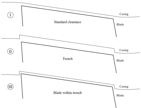
FIGURE 1: CASING LINER TRENCH FORMATION
To understand the realistic size and topology of liner trenches that form in operational engines over their lifetime, an in house tip-rubbing prediction tool was used. The tool input pa-rameters include the blade and casing geometries and the num-ber of engine cycles. The various blade tip and casing positions are predicted and, through calculating when they intersect, the new casing profile is built up cycle by cycle. This tool uses a whole engine model to give the predicted positions of compo-nents based on their expansion under varying rotational loads at conditions through each engine cycle. The untwist of the fan blades under load (which causes the leading and trailing edges to move radially different amounts) is included, as is the varia-tion of the axial posivaria-tion of the blade. Together these effects are responsible for producing the steps at either end of the trench. Additionally, a gust prediction model, that can simulate the sud-den shift of the core radially within the nacelle, is used. This uses data on the likelihood of gusts occurring each engine flight and adds the resulting displacement into the tip-rubbing prediction tool. Gusts are the most significant contributor to casing liner trenches’ depths.
For this study the tip-rubbing prediction tool was used to predict the range, depth and variety of trench geometries and clearances likely to exist in an engine throughout its lifetime. This provides values for the maximum depth of cut and the up-stream/downstream positions that the trenches extend to. These are used to define the boundaries for the geometries to be inves-tigated. The exact clearance levels studied are proprietary how-ever, and cannot be included in this paper.
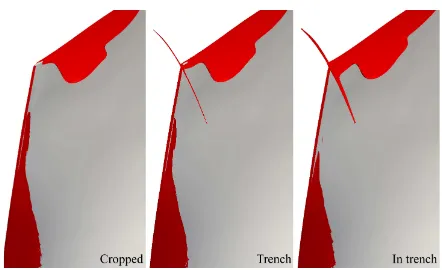
Topologies under investigation
To understand the effects of casing liner trenches three types of tip clearance must be modelled. These are shown in Figure 2. Firstly, a blade with a standard clearance is simulated, and the
ef-fect on the fan aerodynamics of increasing the clearance through cropping the blade tip understood. This is the method usually used to vary blade clearance in simulations, and also represents the result of shortening a blade design to prevent any rubbing oc-curring should this be a concern. In this study the datum casing streamline is always kept constant (outside of the trench region). This is important as attempting to vary the clearance by adjusting the entire casing streamline would modify the inlet and exit ar-eas of the fan, adding extra variables into the computations that would confuse the results. The second geometry that requires simulating is trenches above the blade tip, with the blade tip re-maining outside of the trench and below the datum casing line. This allows an understanding of the impact of a trench appearing above the blade tip for an unchanged blade geometry, as well as a comparison to increasing clearance through cropping the blade. Finally the blade should be allowed to extend inside of the trench, to see whether allowing a blade to extend further radially would provide any benefit, and whether interference from the trench steps has any impact. The clearance will be varied for each of the geometry types.
FIGURE 2: REPRESENTATION OF THE TIP TOPOLOGIES
UNDER INVESTIGATION
SIMULATION SET UP
[image:4.612.340.565.351.523.2]FIGURE 3: LOCATION OF TRENCH WITHIN SIMULATION SET UP
trench steps can be seen in Figure 3. At the inlet a radial distri-bution of total pressure and temperature is used and at the exit boundaries radially averaged mass-meaned non-dimensionalised flow rate (capacity) is specified. The Spalart-Almaras turbulence model [18] is used for all of the simulations presented here.
The turbomachinery meshing and design system PADRAM [19] is used to create the structured multi-block meshes. A range of mesh sizes was tested until mesh independance was indicated for both the overall mesh count and the number of radial cells in the tip gap. The selected mesh has a total mesh size of 4.4M cells with 40 cells in the tip gap for the datum clearance. An extra mesh block is created above the blade tip when a trench is present to properly model the flow. When tip clearance is var-ied in this study (through a trench or cropping the blade tip) the number of radial cells in the tip gap is varied proportionally while maintaining those in the remainder of the span. The mesh across the tip gap is well aligned with the leakage flow direction. Figure 4 shows an example of the trench and clearance mesh used at the blade tip. The y+measured along the blade surface at mid-span and along the casing above the blade tip at mid-chord is of the order of one.
Validation
[image:5.612.325.567.78.220.2]A comparison of the simulated blade with experimental data can be seen in Figures 5 and 6. Both the pressure ratio and effi-ciency curves match the experimental data well, though there is a slight delta to the overall values and stall margin. The radial curves show good comparison to experimental data, although the radial variation in efficiency is under-predicted compared to the experiment. Overall the simulation compares well, lying within 1% across the range of flow rates.
FIGURE 4: A TYPICAL PADRAM MESH ACROSS A
CLEARANCE WITH TRENCH
0.86 0.88 0.90 0.92 0.94 0.96 0.98 1.00 Normalised massflow
0.94 0.96 0.98 1.00 1.02 1.04 1.06
Normalised PR
0.88 0.90 0.92 0.94 0.96 0.98 1.00 1.02
Normalised Efficiency
Experiment Simulation PR Simulation Eff
FIGURE 5: COMPARISON OF SIMULATION WITH
EXPER-IMENT
0.70 0.75 0.80 0.85 0.90 0.95 1.00 Normalised PR 0
20 40 60 80 100
Span / %
Simulation Experiment
(a) Pressure ratio
0.70 0.75 0.80 0.85 0.90 0.95 1.00 Normalised Efficiency 0
20 40 60 80 100
Span / %
Simulation Experiment
(b) Efficiency
FIGURE 6: RADIAL PROFILES VS EXPERIMENT AT
[image:5.612.331.560.275.434.2] [image:5.612.331.552.490.657.2]TIP AERODYNAMICS FOR THE DATUM BLADE
[image:6.612.60.225.287.447.2] [image:6.612.334.571.478.656.2]The tip leakage vortex is common to all rotating blades with a clearance. The basic mechanism involves flow from the pres-sure side of the blade being driven through the clearance by the pressure gradient to the suction side. As this leakage flow exits the clearance and interacts with the passage flow, the difference in velocities causes a vortex to form. Figure 7 shows 3D stream-lines that highlight the vortex produced for this case. The loss and blockage generating nature of the vortex can be seen in the 2D slices of entropy that highlight the path the vortex takes. The tip leakage vortex would normally be expected to begin at the leading edge of the blade, before increasing in size and progress-ing further across the passage as leakage flow along the remain-der of the chord adds to the vortex. As can be seen however in Figure 7, for this case the tip vortex begins around 0.3 chord. The reason for this is described below.
FIGURE 7: TIP LEAKAGE VORTEX HIGHLIGHTED BY 3D
STREAMLINES AND SLICES COLOURED BY ENTROPY
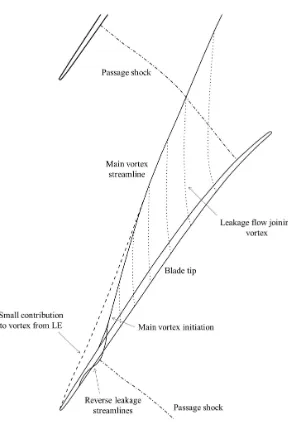
A visualisation of the flow streamlines within the tip gap is useful to understand the formation of the tip clearance vortex. A constant span slice taken halfway between the blade tip and the casing can be seen in Figure 9a. The image is coloured by relative Mach number and faint streamlines added to show the flow directions in the plane of the slice. It can be seen how flow from the pressure side turns perpendicularly as it passes over the tip of the blade. It then exits the suction side and becomes en-trained in the vortex. The path of the vortex at this height can be clearly seen in the streamlines that pass diagonally from near the LE towards the adjacent blade. Figure 9b gives a schematic of the vortex formation method.
It is interesting to see that the formation of the main vortex does not start at the very LE of the blade. A small vortex can be seen emanating from the LE, but shortly after this there appears to be no flow streamlines passing from the blade gap. In fact, the
streamlines actually reverse in this location, before (at roughly 0.3 chord), reverting to the expected direction and forming the main vortex that continues into the passage.
The cause for this unusual leakage behaviour is the accelera-tion upstream of the passage shock that impinges on the pressure surface of the blade at around 0.2 chord. The low pressure region just upstream of the shock creates a pressure gradient from suc-tion side to pressure side, which tries to drive the air back across the tip gap around this location. This effect is a critical feature of the tip aerodynamics for this blade, and has an impact on the fan clearance behaviour studied throughout this work.
Figure 8 shows the chordwise tip leakage massflow distri-bution for the datum case at design point. The data has been normalised by the maximum value at datum clearance. The in-fluence of the sudden change in the flow field around the passage shock is felt by the blade loading near the tip. The high velocity upstream of the shock leads to the pressure difference between upper and lower surface actually reversing, meaning the blade loading is trying to force flow ’backwards’ from suction to pres-sure surface. The resulting tip leakage is meapres-sured through sec-tions of a radial plane created along the camber line within the tip clearance and is normalised by the measured area. Some tip leakage occurs at the LE of the blade but then the amount drops to almost zero, before at 0.2 chord returning to more typical be-haviour. This is where the main vortex forms.
The importance of the chordwise distribution of tip leakage has not been discussed in detail in the literature. Previous re-searchers have acknowledged that chordwise variations in leak-age flow occur and that it is the tip pressure field that controls this [2]. However the impact that this can have on the tip leakage aerodynamics has not been highlighted.
0.0 0.2 0.4 0.6 0.8 1.0
Chord 0.0
0.5 1.0 1.5 2.0 2.5 3.0 3.5
Normalised tip leakage massflow
Datum clearance Twice datum clearance Thrice datum clearance
FIGURE 8: TIP LEAKAGE DISTRIBUTIONS FOR VARIOUS
(a) Clearance streamlines and relative Mach no. contours (b) Schematic of vortex formation
FIGURE 9: CLEARANCE VORTEX FORMATION METHOD
Variation in performance due to cropping blade tip This section discusses the impact on blade performance of increasing clearance through cropping the blade tip. The signifi-cance of the tip leakage distribution defined by the shock location is again apparent from Figure 8. Increasing clearance can be seen to only have a significant effect after 0.2 chord, whereas before this point the lower pressure difference across the tip means that the increase in clearance area does not give the same change in massflow. The shock position fixes the lowest leakage point, and dictates the leakage distribution. Towards the TE of the blade a proportional relationship between clearance and leakage flow can be seen, but near the LE this is not the case.
It can be seen in Figure 10 how the strength of the leakage vortex develops as the gap increases. The leakage vortex cores are highlighted by contours of high q-criterion. Q-criterion is a measure of vorticity, and hence these contours surround and re-veal the vortex cores. The vortex core is larger and moves further across the passage as the clearance increases. The vortex also forms at a greater angle to the blade as the greater momentum of the increased leakage competes with the passage flow.
Figure 11 shows the increase in tip region loss associated with cropping the blade tip. The values have been normalised by the maximum loss for datum clearance. The increased tip leakage massflow and the resulting larger vortex means there is greater mixing with the passage flow and generation of losses. The increased maximum loss in the tip region and the radial ex-tent of the losses due to leakage can be seen. It is obvious from this figure how significant the loss due to tip leakage flow is,
[image:7.612.368.512.79.290.2]hav-(a) Datum clearance (b) Twice datum (c) Thrice datum
FIGURE 10: Q-CRITERION ISOCONTOURS (108)
SHOW-ING CHANGE IN VORTEX WITH CLEARANCE
ing far greater magnitude than lower down the span.
[image:7.612.324.570.363.490.2]0.0 0.5 1.0 1.5 2.0 Normalised loss
92 93 94 95 96 97 98 99 100
Span / %
[image:8.612.330.566.84.241.2]Datum clearance Twice datum clearance Thrice datum clearance
FIGURE 11: TIP REGION LOSS DUE TO CROPPING BLADE
0.0 0.5 1.0 1.5 2.0 2.5 3.0
Relative gap 0.997
0.998 0.999 1.000 1.001
[image:8.612.55.272.89.252.2]Normalised efficiency
FIGURE 12: VARIATION IN BLADE PERFORMANCE WITH
CLEARANCE (DUE TO CROPPING TIP)
MODELLING TRENCHED CASING GEOMETRIES
[image:8.612.48.267.319.485.2]To understand the impact on the tip aerodynamics of trenches above the blade tip, the three types of geometry shown in Figure 2 were simulated. Each case was simulated with a range of clearances between the blade and casing. This was achieved by either ’cropping’ the length of the blade for the case with no trench (type I in Figure 13), raising the depth of the trench above a constant blade (type II), or by increasing the length of the blade inside of a large trench (type III). The clear-ances are all referred to here by their relative magnitudes to da-tum clearance.
FIGURE 13: REPRESENTATION OF THE GEOMETRY
TYPES UNDER INVESTIGATION
Comparison of different trench topologies
The variation in performance due to cropping the blade tip was discussed above and is given in Figure 12. To compare the effect on blade performance of this to varying the clearance with trenches, four clearances were simulated for each geometry type. Representations of the various clearances simulated can be seen in Figure 13. The results are given in Figures 14 and 15. The result have been normalised by the datum clearance value.
1.0 1.5 2.0 2.5 3.0 3.5 4.0 Relative clearance 0.997
0.998 0.999 1.000 1.001 1.002 1.003
Normalised PR
I Cropped II Trench III In trench
(a) Pressure ratio
1.0 1.5 2.0 2.5 3.0 3.5 4.0 Relative clearance 0.9996
0.9998 1.0000 1.0002 1.0004 1.0006 1.0008
Normalised TR
I Cropped II Trench III In trench
(b) TR
FIGURE 14: PR AND TR VARIATION WITH CLEARANCE
[image:8.612.323.565.434.635.2]relation-ship between pressure ratio and clearance for each of the geom-etry types. As the blade is cropped for type I the PR decreases. However a different behaviour is seen for the trench case. As the trench is introduced above the blade and increased in depth, the overall pressure ratio remains almost constant. For the in-trench case (type III), extending the blade inside of the trench follows the same linear gradient of PR as the case with no trench. The impact of varying the trench depth above the blade tip clearly has a different effect to cropping/uncropping the blade.
Figure 14b shows the variation of temperature ratio with clearance. It can be seen that the gradient of TR with clear-ance does not follow that of PR from 14a. This is due to the increased losses associated with increased clearance, caused by extra tip leakage massflow and mixing of the tip leakage vortex. These viscous effects result in additional non-isentropic temper-ature generation which increases the tempertemper-ature ratio, despite little variation in pressure ratio. For the cropped and in-trench cases the variation in TR is caused by a combination of the PR variation and the increase in viscous heating. The overall TR de-creases with clearance for these cases, because the variation in PR (and therefore isentropic TR) is greater than the TR change due to extra tip leakage effects.
To understand the impact of the three different cases on per-formance, the variation in blade efficiency can be analysed. This is given in Figure 15. It can be seen that the gradient of efficiency with clearance is steeper for the cropped (I) and the in-trench (III) cases than for the trench case. The geometries where the blade is being cropped are most sensitive to clearance, and very similar to one another, suggesting the performance gradient is not sensitive to whether the blade tip is sat in or out-side of the trench. It is the difference between cropping the blade or varying the clearance through a trench that is most significant.
To understand the performance differences between the three cases, geometries with the same clearance for each case can be directly compared. Figure 15 shows a delta in efficiency for geometries with twice datum clearance from each case. The radial profiles of loss for these are given in Figure 16. These were taken at 0.9 chord (’within’ the trench in the axial direction), to ensure the effect of tip region features could be clearly seen. It can be seen that the extent of tip region loss is lower for the blade within the trench compared to the other two. The trench case also has less tip region loss than the cropped blade. This shows that lower tip region loss is produced when the clearance is moved further radially via a trench. It can also be seen how the region of the span affected by the tip loss has been shifted radially, moving the leakage out of the main passage flow. The effects seen match the explanation by Robideau [15], who described how moving the clearance outside of the main flow path is beneficial.
1.0 1.5 2.0 2.5 3.0 3.5 4.0 Relative clearance
0.996 0.997 0.998 0.999 1.000 1.001
Normalised efficiency
[image:9.612.325.551.89.261.2]I Cropped II Trench III In trench
FIGURE 15: EFFICIENCY VARIATION WITH CLEARANCE
0.0 0.2 0.4 0.6 0.8 1.0
Normalised loss 0.95
0.96 0.97 0.98 0.99 1.00
Normalised radius
[image:9.612.330.573.317.487.2]I Cropped II Trench III In trench
FIGURE 16: TIP REGION LOSS FOR THE DIFFERENT
CASES AT TWICE DATUM CLEARANCE, MEASURED AT 0.9 CHORD
Flow visualisation
To further understand the differences between the tip region flow and losses for the three cases as described above, visual-isation of the tip flow features are given in Figures 17 and 18. These confirm that seen in Figure 16. Figure 17 demonstrates how raising the clearance through a trench shifts the leakage vor-tex radially. The spanwise slices shown are at a constant height just below the casing streamline, and show how the vortex size and intensity at this height is reduced by raising the clearance via a trench.
of the trailing edge step, looking upstream. These highlight the vortex size and intensity for each case. It can be seen how lower vortex intensity and entropy is present where the clearance has been raised radially via a trench. This shows the impact of the trench on the main passage flow outside of the trench region, in-dicating that shifting the leakage flow radially reduces the losses generated.
FIGURE 17: REL. MACH NO. CONTOURS SHOWING THE
[image:10.612.319.576.258.389.2]VARIATION IN VORTEX SIZE AT A CONSTANT RADIUS FOR TWICE DATUM CLEARANCE
FIGURE 18: VARIATION IN BLOCKAGE INTENSITY
DOWNSTREAM OF TRAILING EDGE STEP FOR EACH CASE AT TWICE DATUM CLEARANCE
The influence of trench steps
An additional objective was to understand the importance of the trench steps themselves and whether they have any direct influence on the tip flow behaviour. Figure 19 shows contours of separated flow in the LE and TE tip regions. The separation
caused by the LE BFS and the TE FFS can be seen, as well as the tip leakage flow. It can be seen that the LE trench step sep-aration does not directly interact with the tip leakage flow. The extent of the separation is not great enough for this to happen and also the tip leakage vortex is initiated away from the blade LE, as discussed previously. The TE trench step appears more signif-icant. The leakage flow can be seen to directly interact with the TE step, and separation at the step is reduced on the suction side, where the leakage vortex passes over it. The separation at the TE step enters the main passage flow, and is therefore likely to have greater impact that separation from the leading edge step. The increase in entropy due to the TE FFS can be seen as the dark red contour along the top right of the in trench image in Figure 18.
FIGURE 19: THE INFLUENCE OF TRENCH STEPS (ZERO
AXIAL FLOW CONTOURS SHOW SEPARATION)
Radial profiles
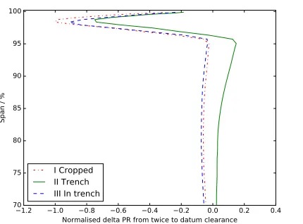
Aside from the differences in the tip region behaviour be-tween the three cases, the gradients of performance with clear-ance are also shown to vary. Figure 14a showed how for the trench case the PR appeared to stay almost constant while when cropping the blade tip a drop in PR was seen. Figure 20 shows the delta in radial PR profiles from twice datum clearance to da-tum clearance for each of the three cases.
[image:10.612.41.283.424.550.2]1.2 1.0 0.8 0.6 0.4 0.2 0.0 0.2 0.4 Normalised delta PR from twice to datum clearance 70
75 80 85 90 95 100
Span / %
[image:11.612.61.276.84.243.2]I Cropped II Trench III In trench
FIGURE 20: DELTA PR RADIAL PROFILE FROM TWICE TO
DATUM CLEARANCE FOR EACH CASE
The above results demonstrate the differences between crop-ping the blade tip and varying clearance through a trench, and the mechanisms that lead to differences between the tip region flows and overall performance values. To gain a more complete un-derstanding and investigate which regions of the clearance and trench are most critical to control performance, a more complete parameterisation is needed.
FULL PARAMETRIC STUDY
To fully understand the effect of casing liner grooves and the impact of the large variety of possible casing shapes, a detailed parametric model has been developed. The parametric model is able to generate casing liner profiles and varying tip clearances to be used within the PADRAM meshing system. The parametric model consists of eight parameters allowing varying blade clear-ances and trench depths from LE to TE, with different up and downstream trench step heights and axial positions. Figure 21 shows the parameters controlled in the model:
FIGURE 21: REPRESENTATION OF THE PARAMETRIC
DEFINITION OF THE GEOMETRY
The parametric model allows chord-wise variation of both the casing and blade geometries. The blade tip and casing pro-files are generated through a linear interpolation of the specified parameters. It is necessary to model chord-wise variation of the trench depth as this occurs in an engine as the blade cuts differ-ently at the leading and trailing edges. Uneven blade tip clear-ances from LE to TE can also occur in an engine due to varying untwist of the blade during expansion.
Design of experiment
To understand the influence of each parameter on the blade performance, simulations of various combinations of the param-eters were carried out. To plan the set of design points to simulate a design of experiments approach was used. Through the Rolls-Royce optimisation toolbox SOFT [20] a latin hypercube [21] design of experiments was set up. Latin hypercube sampling is a method for generating a near-random distribution of parameter values for a multidimensional system. Unlike truly random sam-pling, where there is no guarantee of the distribution of sample points, latin hypercube sampling attempts to ensure a good rep-resentation of the real variability by ensuring the design space is evenly covered. This was used to maximise the relevance of the results obtained through the surrogate modelling approach to be used.
The trench and gap parameters could vary up to three times datum clearance, while the axial step positions could vary up to five times. Fifty sample points from the design space were selected to be simulated through the latin hypercube sampling. The objective function extracted from each simulation and to be used in further analysis is efficiency.
Surrogate model
[image:11.612.38.290.568.661.2]To find the dependence of blade performance to each param-eter, a polynomial response surface analysis method was used [22]. This is a surrogate modelling method that allows an empir-ical model to be built from the results of the simulations carried out, allowing the response (blade performance) to be predicted given the input variables (geometric parameters). A first order polynomial response surface was fitted to the data. This allows a coefficient for each parameter to be found, allowing an equation to be formed that relates the blade performance to each of the input parameters.
Figure 22 shows a comparison of the first order RSM versus the data to which it was fitted for each point run in the DoE. It can be seen that the model fits the data well, accurately reflecting the variation in efficiency of each design. This gives confidence that the model is reflecting the physics captured by the CFD and that the linear trends predicted are a good representation of the real effects of each parameter.
pa-0 10 20 30 40 DoE Iteration
0.9970 0.9975 0.9980 0.9985 0.9990 0.9995 1.0000 1.0005
Normalised efficiency
CFD Simulation RSM Model
FIGURE 22: COMPARISON OF RSM FIT TO CFD DATA
rameter and C a coefficient. The calculated coefficients (C) for each parameter found via the response surface method are given in Table 1. A negative coefficient means blade efficiency reduces with increased magnitude of that parameter. The constant in the equation is the efficiency value that a geometry with zero clear-ance or trench has, equivalent to setting all gap and trench pa-rameters to zero.
[image:12.612.38.293.78.225.2]f=X1×C1+X2×C2+...+Xn×Cn+const (1)
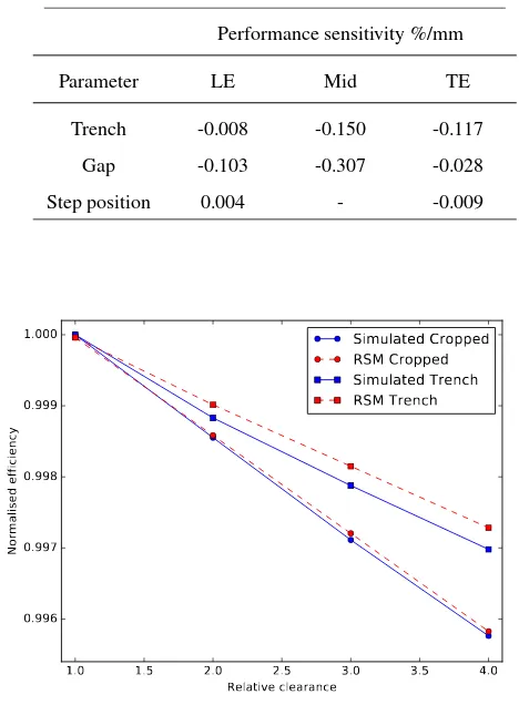
Figure 23 shows a comparison of previously obtained simu-lated results versus predictions from the response surface model. This can be used to assess the ability of the polynomial response surface to represent the real effect of each parameter. The points shown here were not sampled during the response surface analy-sis. It can be seen that the polynomial equation obtained does a good job of predicting the gradient of efficiency to clearance for the two cases.
It can be seen in Table 1 that the axial position of the trench steps is of far less importance than the clearance magnitudes. The axial position of the trench steps does not seem that impor-tant. While the separation at the steps may have an influence, the position of the steps relative to the blade LE/TE is not that critical. The relationships also indicate the trench and mid-blade clearance parameters are most important. However, to un-derstand which region has the most influence on the blade perfor-mance, the relationship of the clearance area to the parameters in the model must also be considered. If every parameter in the ge-ometric model were kept at zero, then the LE and mid-trench val-ues increased in turn, it would be obvious that increasing the mid value increases the clearance area by twice as much as the LE parameter. Hence, the mid values (of both blade and trench) ge-ometrically have twice the influence on tip leakage as the LE/TE values in this model.
TABLE 1: MODEL COEFFICIENTS FOR EACH
GEO-METRIC PARAMETER - EFFICIENCY VARIATION WITH CLEARANCE
Performance sensitivity %/mm
Parameter LE Mid TE
Trench -0.008 -0.150 -0.117
Gap -0.103 -0.307 -0.028
Step position 0.004 - -0.009
1.0 1.5 2.0 2.5 3.0 3.5 4.0 Relative clearance
0.996 0.997 0.998 0.999 1.000
Normalised efficiency
Simulated Cropped RSM Cropped Simulated Trench RSM Trench
FIGURE 23: COMPARISON OF SIMULATED AND
PRE-DICTED PERFORMANCE VARIATIONS WITH CLEAR-ANCE
To understand the effect of equivalent variations in clearance at the LE, mid and TE, the RSM coefficients must be normalised by the clearance area that they influence. The result of this can be seen in Table 2.
Explanation of the coefficients
Table 2 gives a comparison of the influence on blade per-formance of different regions of the tip/trench clearance. It can be seen that overall the sensitivity of performance is greater due to cropping the blade tip than increasing the depth of trench, re-flecting results found earlier. The chordwise distribution of this sensitivity varies however between the gap and trench.
[image:12.612.324.558.126.444.2]for-TABLE 2: TRENCH AND GAP COEFFICIENTS ADJUSTED BY THEIR INFLUENCE ON CLEARANCE AREA AND NORMALISED
Adjusted performance sensitivity
Parameter LE Mid TE
Trench -0.05 -0.49 -0.76
Gap -0.67 -1.00 -0.18
mation for this case. Due to the nature of the passage shock position controlling the tip leakage distribution, the tip leakage vortex is initiated around thirty percent of chord. It is therefore around this point that the leakage massflow will have the greatest impact on vortex formation, and therefore changes to clearance in this area will have the greatest impact on blade performance.
The sensitivity of performance to the trench clearance mag-nitudes is reduced compared to the gap sensitivities due to the partially positive effect that adding a trench and raising the clear-ance has. This can be seen in the individual sensitivities. The LE trench clearance is far less critical than the LE gap clearance, due to the benefit that it provides by moving the critical region of vortex formation radially out of the passage flow. The TE trench parameter is significant however, and the impact of the trench is biased towards the TE. This demonstrates the difference be-tween the impact of the LE and TE trench steps. The TE trench step acts as a FFS, and the separation due to this generates losses and enters the passage flow. The LE BFS separation does not have the same impact, any separation is confined to the corner of the LE trench step, remaining out of the flow path, and does not have any influence on the downstream flow.
Additional impact of clearance variaitons
Aside from variations in the tip region, an additional effect of varying clearances and trench geometries that must be noted is the influence of the tip flow behaviour on flow in the remain-der of the span. Changes in blockage and local velocities at the tip can slightly influence the radial distribution of massflow and velocities for the rest of the blade. An impact of this can be seen in Figure 24.
[image:13.612.337.558.69.204.2]This shows that separation at the blade TE is affected by dif-ferent clearance geometries and sizes. The effect of this can also be seen in Figure 20 where localised changes at the tip cause an additional effect from 95% span and below. This will result in a secondary impact on the blade performance, aside from changes localised to the tip region, and the performance variations with clearance discovered for each trench parameter also include these effects.
FIGURE 24: VARIATION OF TRAILING EDGE
SEPARA-TION DUE TO DIFFERENT CLEARANCE TYPES
The upshot of this is that the performance trends given are influenced by the overall blade design and aerodynamic be-haviour away from the tip region. This bebe-haviour is specific to this fan blade design, and therefore the relationships found may not be directly applicable to blades with different designs. This must be considered when trying to translate tip performance trends found for one blade to another, or develop generic rela-tionships.
CONCLUSION
This paper has investigated the tip region aerodynamics of a modern fan blade. The tip flow features, tip leakage distribution, clearance vortex size and tip loss have been studied for the da-tum design, as well as the effect of increasing clearance through cropping the blade tip. It was shown how an unusual tip leakage distribution exists due to the acceleration near the passage shock controlling the chord-wise vortex initiation location.
A parametric model was used to compare the effect of in-creasing clearance through cropping the blade tip, creating a trench above the blade tip and modifying the blade length inside of a trench. It was shown that a benefit is achieved by increas-ing the clearance via a trench compared to croppincreas-ing the blade tip. This is due to lower tip region loss being generated when the clearance is raised radially out of the main passage flow.
[image:13.612.53.273.142.209.2]This work has discovered performance relationships for tip geometries and clearances that can be used to influence fan blade design and understand engine performance degradation in-service. It is also apparent from this work that these relationships depend on the specific tip aerodynamics of the blade under inves-tigation. The presence of a passage shock, the tip leakage distri-bution, shock-vortex interaction and overall blade design influ-ence the tip flow behaviour and associated performance variation with clearance.
FUTURE WORK
It would be interesting to apply this methodology to other fan/compressor blades to understand how specific the trends shown here are to this blade design, and whether generic rela-tionships could be discovered.
ACKNOWLEDGMENT
The first author is funded by a scholarship from the Univer-sity of Sheffield. The authors would like to thank Rolls-Royce for their support and permission to publish the work.
REFERENCES
[1] Denton, J. D., 1993. “Loss mechanisms in turbomachines”. In ASME 1993 International Gas Turbine and Aeroengine Congress and Exposition, American Society of Mechanical Engineers, pp. 621–656.
[2] Storer, J., and Cumpsty, N., 1994. “An approximate anal-ysis and prediction method for tip clearance loss in ax-ial compressors”. Journal of Turbomachinery, 116(4),
pp. 648–656.
[3] Sieverding, C., 1985. Tip clearance effects in axial turbo-machines: April 15-19, 1985. Von Karman Institute for Fluid Dynamics.
[4] Kammer, A. S., and Olgac, N., 2016. “Blade/casing rub interaction in turbomachinery: Structural parameters influ-ence on stability”.Journal of Propulsion and Power, 32(1),
pp. 1–10.
[5] Ma, H., Yin, F., Guo, Y., Tai, X., and Wen, B., 2016. “A re-view on dynamic characteristics of blade–casing rubbing”. Nonlinear Dynamics, 84(2), pp. 437–472.
[6] Fois, N., Watson, M., and Marshall, M., 2016. “The influ-ence of material properties on the wear of abradable mate-rials”. Proceedings of the Institution of Mechanical Engi-neers, Part J: Journal of Engineering Tribology.
[7] Legrand, M., Batailly, A., and Pierre, C., 2012. “Numer-ical investigation of abradable coating removal in aircraft engines through plastic constitutive law”.Journal of Com-putational and Nonlinear Dynamics, 7(1).
[8] Adamczyk, J., Celestina, M., and Greitzer, E., 1991. “The role of tip clearance in high-speed fan stall”. In ASME 1991 International Gas Turbine and Aeroengine Congress and Exposition, American Society of Mechanical Engineers, pp. 109–115.
[9] Sakulkaew, S., Tan, C., Donahoo, E., Cornelius, C., and Montgomery, M., 2013. “Compressor efficiency variation with rotor tip gap from vanishing to large clearance”. Jour-nal of Turbomachinery, 135(3).
[10] Seshadri, P., Shahpar, S., and Parks, G. T., 2014. “Robust compressor blades for desensitizing operational tip clear-ance variations”. In ASME Turbo Expo 2014: Turbine Technical Conference and Exposition, American Society of Mechanical Engineers.
[11] Beheshti, B. H., Teixeira, J. A., Ivey, P. C., Ghorbanian, K., and Farhanieh, B., 2004. “Parametric study of tip clearancecasing treatment on performance and stability of a transonic axial compressor”. Journal of turbomachinery,
126(4), pp. 527–535.
[12] Shabbir, A., and Adamczyk, J. J., 2005. “Flow mechanism for stall margin improvement due to circumferential casing grooves on axial compressors”.Journal of turbomachinery,
127(4), pp. 708–717.
[13] Houghton, T., and Day, I., 2012. “Stability enhancement by casing grooves: The importance of stall inception mecha-nism and solidity”. Journal of Turbomachinery, 134(2).
[14] Qin, N., Carnie, G., Wang, Y., and Shahpar, S., 2014. “Design optimization of casing grooves using zipper layer meshing”.Journal of Turbomachinery, 136(3), p. 031002.
[15] Robideau, B. A., and Niiler, J., 1980. Blade tip seal for an axial flow rotary machine, Dec. 9. US Patent 4,238,170. [16] Korting, P., and Beacher, B., 1989. “Improved compressor
performance using recessed clearance (trenches)”. Journal of Propulsion and Power, 5(4), pp. 469–475.
[17] Lapworth, L., 2004. “Hydra-cfd: a framework for collab-orative cfd development”. In International Conference on Scientific and Engineering Computation (IC-SEC), Singa-pore, June, Vol. 30.
[18] Spalart, P. R., and Allmaras, S. R., 1992. “A one equation turbulence model for aerodinamic flows.”. AIAA journal,
94.
[19] Shahpar, S., and Lapworth, L., 2003. “Padram: Parametric design and rapid meshing system for turbomachinery op-timisation”. In ASME Turbo Expo 2003, collocated with the 2003 International Joint Power Generation Conference, American Society of Mechanical Engineers, pp. 579–590. [20] Shahpar, S., 2001. “Soft: A new design and optimisation
tool for turbomachinery”. ROLLS ROYCE PLC-REPORT-PNR.
code”.Technometrics, 42(1), pp. 55–61.